Failure...or feature?
 08-29-2013, 09:33 AM
#16
Drifting
If it were me, I think I would test to determine if the problem is internal or external to the head unit next. This could be accomplished a couple different ways.
Many modern headunits simply slide in and out once the surrounding trim piece is removed. The trim piece if handled gently is easily removed (and if broken is easily replaced, IIRC about $15 from Roger for a new one). Alternatively, with the console side panel out, the pig tail connectors to the head unit should be accessible.
Either way, a volt meter needs to be used to check for continuous +12v under acceleration. Also, a continuity or resistance test needs to be run on the ground circuit. Since grounds are attached to the chassis in so many places, I'd be more suspect of the ground circuit being interrupted under G-forces.
If are not sure, which wires are for what... post pictures of the wires and connectors.

 11-24-2013, 05:15 PM
#18
Rennlist Member
Thread Starter
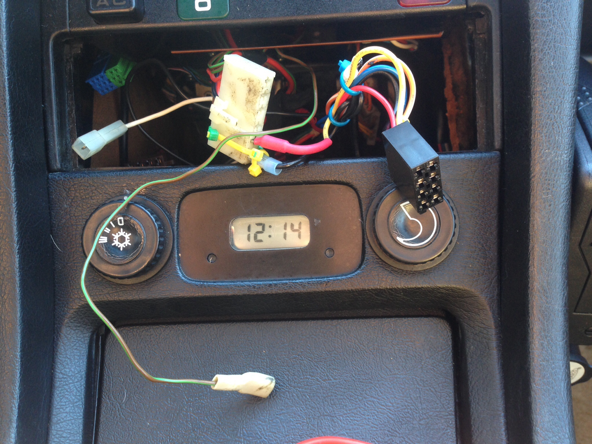
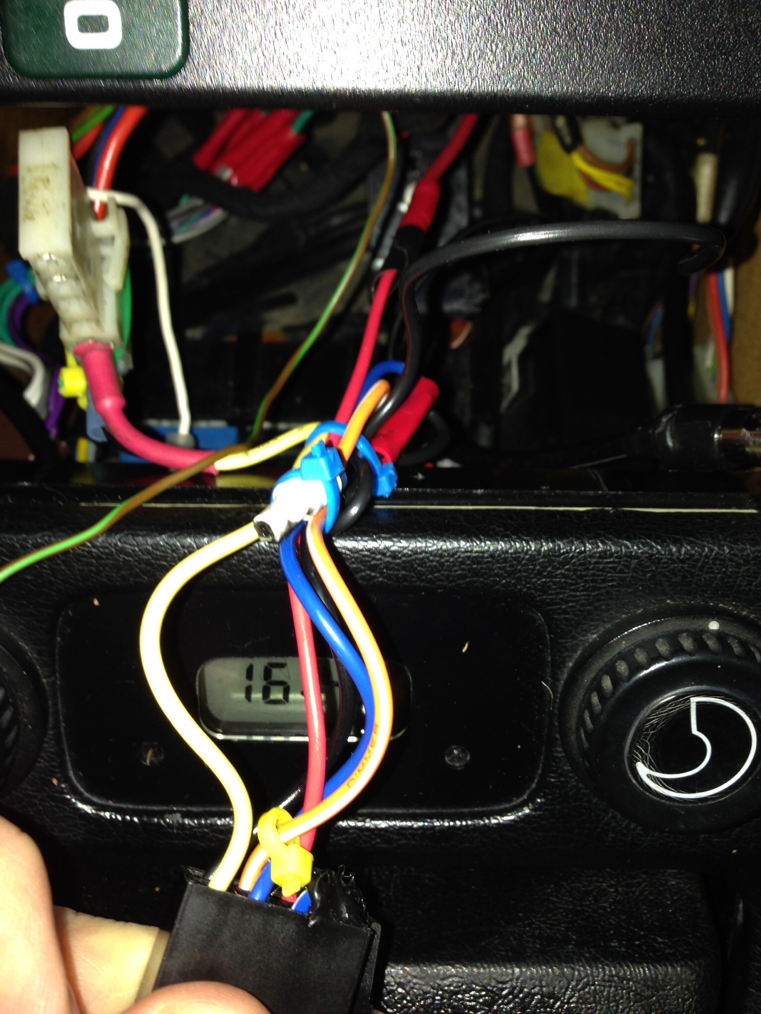
I finally got the chance to do some more checks on this and found a few unconnected wires. I did use my multimeter on the black connector to the radio and found that two wires provided power and neither had issues at throttle. I suspect that the white wire is an antenna booster of some kind, but not sure what it connects to, and not sure what connects to the green/brown wire. Take a look at the pic and let me know your thoughts.
11-24-2013, 07:29 PM
#20
Rennlist Member
Thread Starter
Also the green/brown wire does carry power,if that helps diagnose.
11-24-2013, 08:08 PM
#21
Nordschleife Master
I think that the white wire is the head unit end of the amp activation wire.
I don't see any green/brown wire on the wiring diagrams for the 85. It may be something they added in later years.
11-28-2013, 10:01 PM
#22
Rennlist Member
Thread Starter
I wonder what the brown/green wire is for. It does have live power running on but I have no idea on the connection. It's a bit unclear to me on the wire diagram.
Would love to see what the original connections were to the original radio unit. I only have the current later Porsche radio installed, so I don't know the connections.
Anyone have any thoughts?
Would love to see what the original connections were to the original radio unit. I only have the current later Porsche radio installed, so I don't know the connections.
Anyone have any thoughts?
12-03-2013, 09:02 PM
#23
Rennlist Member
Thread Starter
So I'm doing a little more analysis on the connectors to better understand what does what so that I can track down the short culprit.
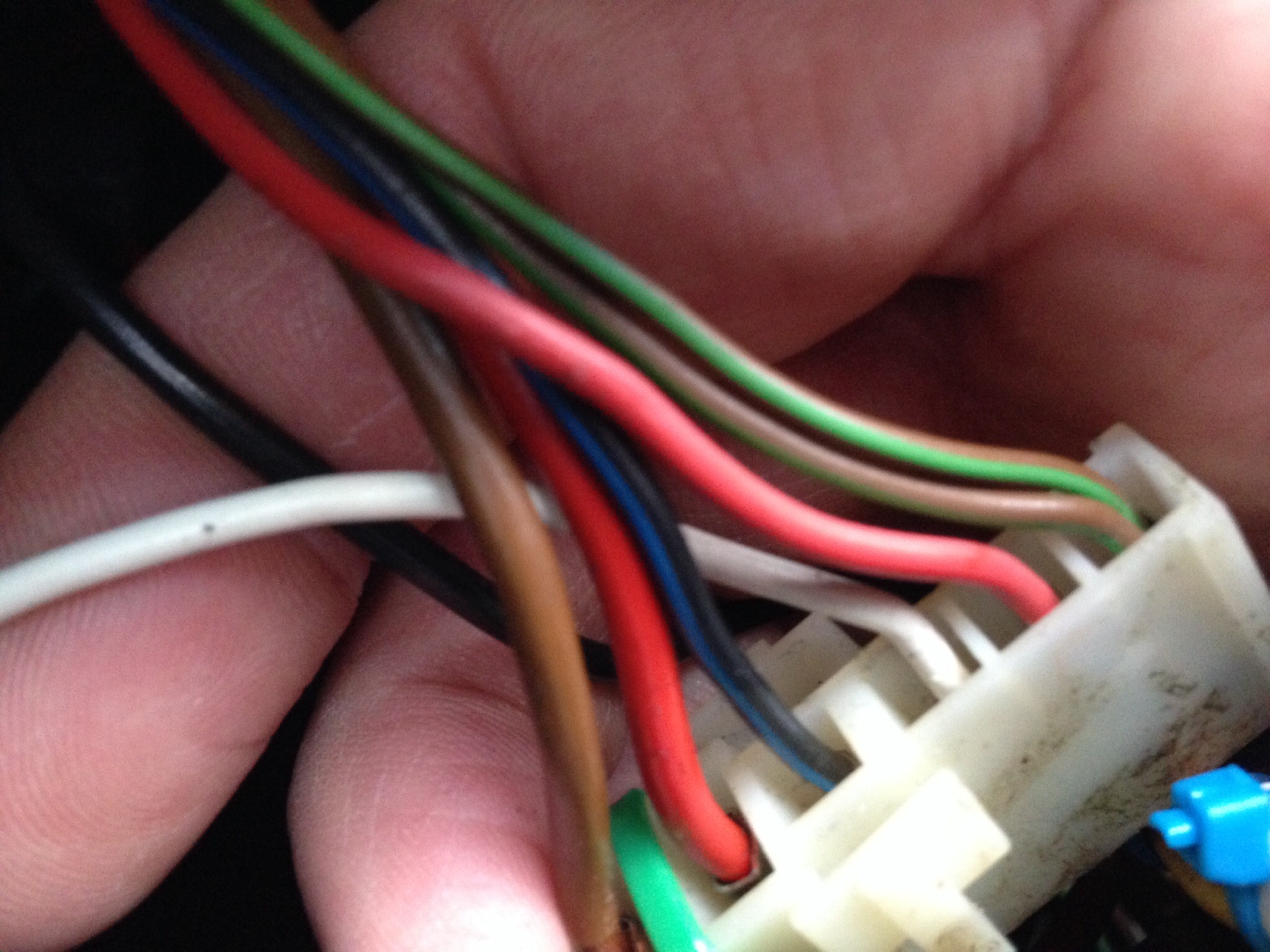
My guess is that the wide white cable junction was actually the connector to the original radio. Of the cables that go into that junction, here is what I found with the micrometer:
Brown - dead
Red - live
Blue/black - dead
White - dead
Pink - dead
Brown/green - live
Not sure what each wire does, though. Does this sound right?
12-03-2013, 09:06 PM
#24
Rennlist Member
Thread Starter
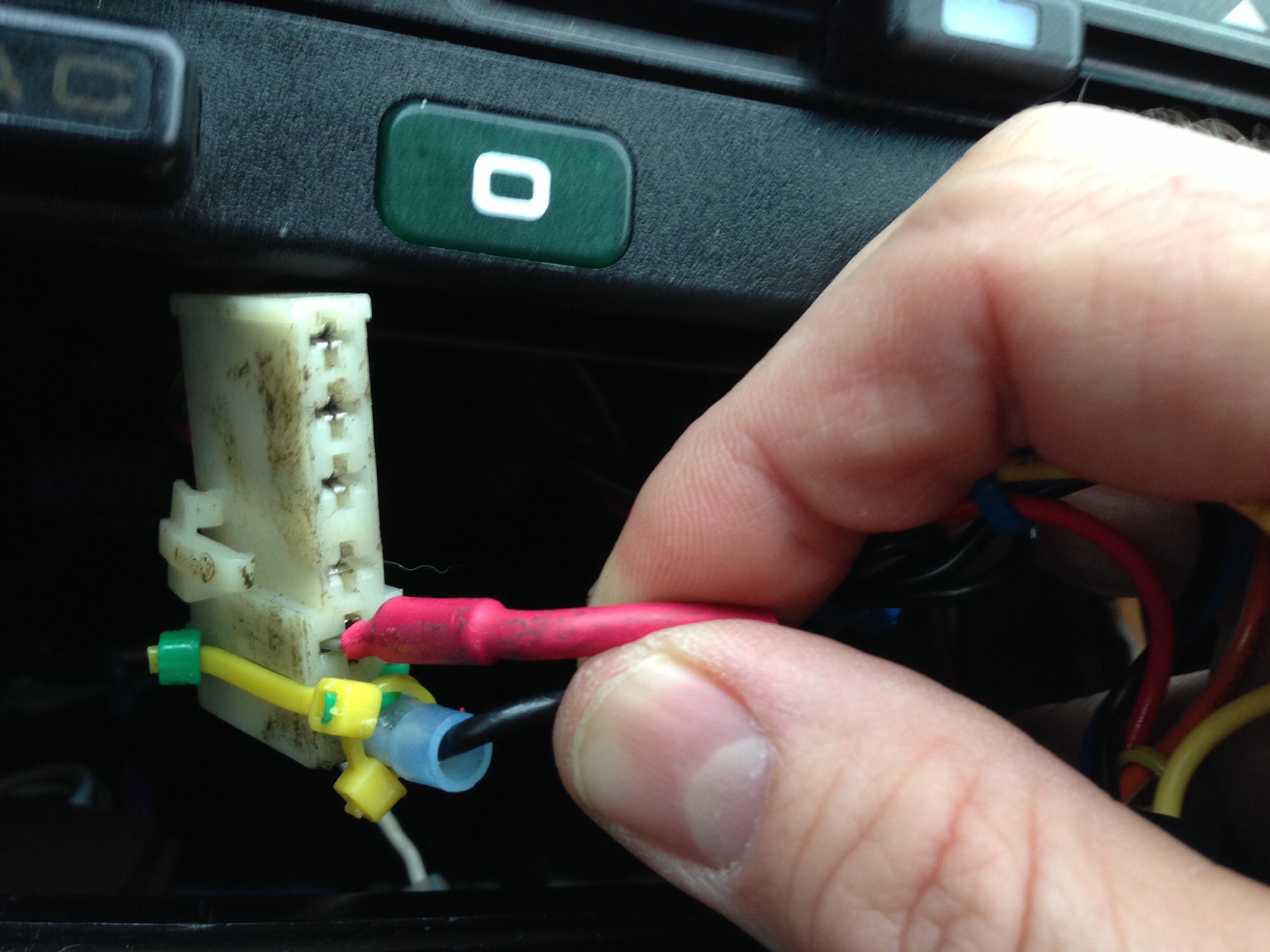
Next, I checked the wires going out from the white junction into the black connector which goes into the radio.
Yellow cable (with red connector) - live
Black - dead
This makes sense as the black is connected to brown in the junction (I suspect ground).
Still make sense?
Yellow cable (with red connector) - live
Black - dead
This makes sense as the black is connected to brown in the junction (I suspect ground).
Still make sense?
12-03-2013, 09:11 PM
#25
Rennlist Member
Thread Starter
Lastly, there are several other wires in the black connector. The two wires from the white junction connect into the black connector, and two other wires connect into it separately.
Yellow - connects to red connector/junction - live
Black - connects to junction (brown) - dead*
Orange/white - cut - dead
Blue - connects to separate black cable - dead
Red - connects to separate red cable - live
My guess is that the separate red cable is tied to the throttle, but I can't tell what's what.
Any ideas on which connector could possibly be shorting when I hit 3K RPM?
12-03-2013, 11:00 PM
#26
Nordschleife Master
The only suggestions I have are:
Blue/Black should be "Illumination." See if it is hot when the dash lights are on.
"Pink" might really be Red/White. That would be "Switched Hot." See if it's hot when ignition is on.
Brown is always ground in these cars. It should show continuity to any ground point or bare metal.
Blue/Black should be "Illumination." See if it is hot when the dash lights are on.
"Pink" might really be Red/White. That would be "Switched Hot." See if it's hot when ignition is on.
Brown is always ground in these cars. It should show continuity to any ground point or bare metal.
12-04-2013, 02:47 PM
#27
Chronic Tool Dropper
Lifetime Rennlist
Member
Lifetime Rennlist
Member

So...
I went back to my radio installation notes in my logbook. (You all keep a logbook for changes you make to the car, right?) I replaced the "Reno" with a Blau "Alaska" a long time ago, and had some initial power supply issues and a solution that may help you. The WSM wiring diagrams don't accurately represent what's in the car, by the way.
Power to the head unit (the RED wire in the original Reno connector you show) is looped through the amplifier area, under that cover next to the passenger seat. There's a connector there with two red wires that connected to the amplifier. With the amp removed or the sensing from the head unit not working, those two red wires need to be jumpered together to pass power to the head unit. Like your PO, I made it a point not to hack any of the original connectors, so I made a jumper that plugs into that connector so the head unit could get power through the factory connector in the console/dash. If your installation is like mine (same year), the problem may be as simple as a loose jumper in that harness. If you are still using the original amplifier, look at all the connections there to make sure that nothing is loose enough to bounce around while accelerating.
I can go shoot a picture of the connector under the cover if you need it.
 12-05-2013, 12:22 AM
#29
Rennlist Member
Thread Starter
Wise man, you are. Although I'm not as thorough as I probably should be, I do track my servicing, updates, enhancements, etc. in a database. It's nice (and sometimes crucial) to have a history of these things.
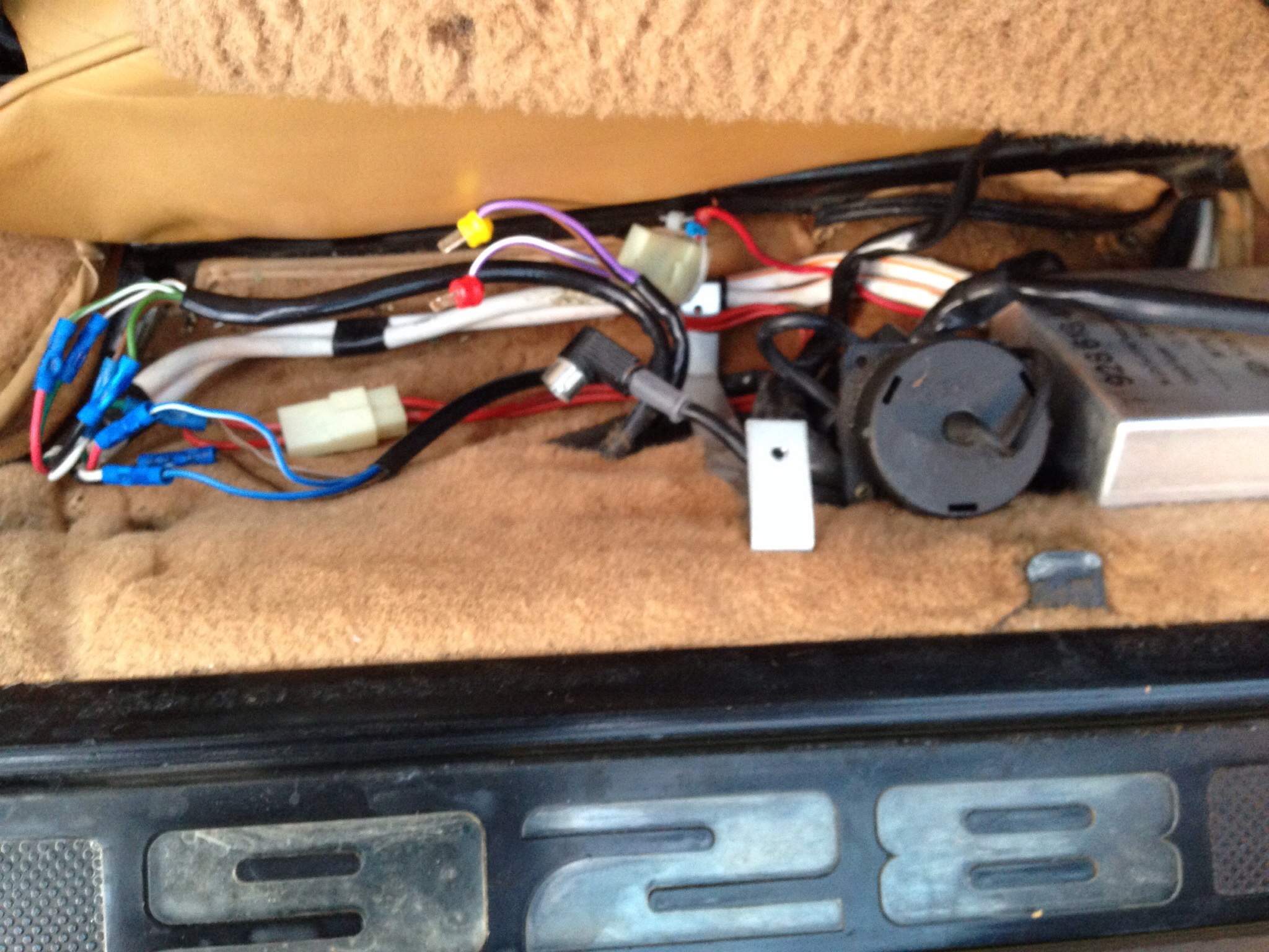
Now as for the amplifier area, I did open it up for the first time and took a picture of what I saw. I can't say what is what in there, so I look to you experts! Below is a pic of what I found, so any pointers would be great.
Lastly, while the issue may be a loose connector, I don't believe that the problem I am having is related to wire movement. I can replicate the issue in neutral at full stop just by reving the engine to 3K. My first goal is to to try to isolate the issue to see if it is the car wiring, or possibly the radio itself.