When you click on links to various merchants on this site and make a purchase, this can result in this site earning a commission. Affiliate programs and affiliations include, but are not limited to, the eBay Partner Network.
I tried this on my 81 928S Euro. I measured something like 500 ohms from yellow and green wires between the locking motors to ground. 12V power connected to either yellow or green directly drew about 6 amps. This of course blew the stock 400ma fuses. I was able to get it to lock consistently by using the keyless entry controller to short the yellow and green wires together. I tried a number of variations but didn't find anything that would cause it to unlock consistently using the factory lock motors.
I put enough time in it and have enough experience with electrical systems to be pretty confident it wasn't a rookie wiring mistake. Could be that the door lock motors in the early cars aren't all the same internally.
12v/500ohms = 24mA so there is no path for 6A there.
Also the stock 400 mA fuses are supplied by the battery (with Key out) so if you connect battery voltage to the other side of the fuse - how does the fuse blow?
The only ground that is supposed to be in this circuit is the ground to each of the lock motors... so the only thing you should be able to do by connecting battery voltage to either the yellow or green wires via any conceivable source is to make the motors run.
Ergo the answer (IF your locks work normally otherwise) is that your KE system is introducing a path to ground (as well as or instead of the intended path to battery voltage). This is the only possible way the fuses can blow if they don't blow otherwise when the central locking works normally.
The KE must not be configured correctly.
You must only use positive locking mode and you need to remove all ground connections at the KE relay. A possible easier solution here is to simply connect the KE lock/unlock outputs to the Yellow & Green/black wires via diodes - cathode end to the yellow & green/black wires
BTW - reminder early cars are the opposite of later cars - NONE of this applies to cars without the 400mA fuses behind the CE panel. e.g. '89 and up are quite different and use negative triggering.
Has anyone actually got a KE to work on an early 928?
I first did mine as per the drawing in post #13 and the 0.4A fuses blow. My basic knowledge of electrics tells me it will work when I study the wire diagrams but it doesn't. This was a while back and this new post open my curiosity again and I wired 12+ as per your drawing to the 15A fuse that power the KE. When testing this fuse blow.
I then try using diodes with same result
If the KE's 15A fuse blows that is a different issue altogether.
It suggests the KE itself has a path to ground - we certainly didn't add one.
Perhaps the KE is faulty - the proposed wiring (or using diodes) has no path to ground except through the lock motors. Something else is going on here.
So played with it a bit more this morning and SUCCESS. IT WORKS
So here's what I found.
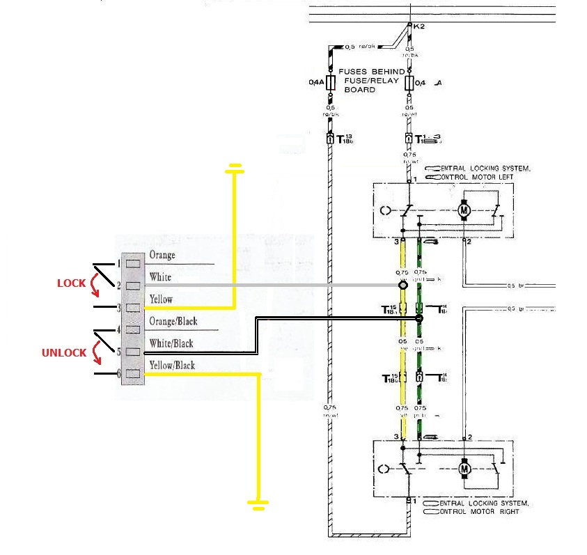
The locks are NEGATIVE TRIGGERED.
The Yellow and Yellow/Black (or whatever your system is) need to be wired to ground.
The LOCK signal to cars Yellow wire
And UNLOCK signal to cars Green/Blue wire.
The KE unit can be used in normal mode, no need for pneumatik mode with more delay on signal.
I changed the diagram used earlier to show the correct wiring.
This is for a 1980
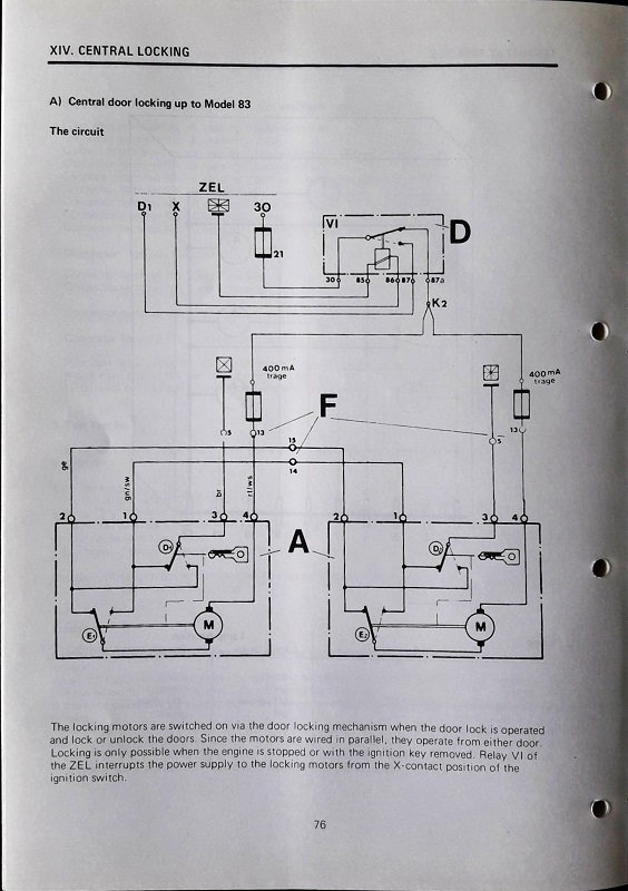
Well that is very odd - your car lock circuit cannot be wired as the diagram shows then... it is clear that the fuses are supplied by battery power (whenever the power windows aren't active). So negative triggering should indeed blow the fuse.
Maybe the actual implementation is different than the diagram in the WSMs?
I believe the internal wiring of the motors is diffrent from the wire diagrams. That's the only thing I can think of as the external wiring is the same.
So played with it a bit more this morning and SUCCESS. IT WORKS
So here's what I found.
The locks are NEGATIVE TRIGGERED.
The Yellow and Yellow/Black (or whatever your system is) need to be wired to ground.
The LOCK signal to cars Yellow wire
And UNLOCK signal to cars Green/Blue wire.
The KE unit can be used in normal mode, no need for pneumatik mode with more delay on signal.
I changed the diagram used earlier to show the correct wiring.
This is for a 1980
Genius! My '88 doesn't have an alarm system and I've been struggling with it all weekend, trying to get it to work with no success. I saw your post and even though an '88 isn't an OB, gave it a try and it works perfectly! I had no trouble installing remote door controls on my '89 or '93 so I didn't think the '88 would be any more trouble but it sure was.
I'm probably going to wire my generic keyless entry this evening....84, no alarm. Keyless entry is just doors, hatch, light flash. Off the top of my head, I can't see any reason for diodes for my installation (maybe I'm missing something but I'm guessing that would apply for cars with alarms?). My question is about wiring to make the turn signals flash....what seems to be the easiest location to hook in to those circuits?
Kevin,
You will need diodes for the turn signals for sure - unless your KE system has 2 independent flash outputs (not many do). For lock & unlock you may not need diodes. CE panel is the best place to intercept the turn signals. The hatch is not at all straightforward.


 02-07-2017, 09:24 PM