

Hall Sensor and Crank Position Sensor Harness
 07-13-2012, 11:46 AM
#1
Rennlist Member
Thread Starter
All,
I am un-burying this from an Intake thread I have further down in hopes someone can help me:
I have a Hall and a Crank Position Sensors whose plastic connectors disintegrated and I have not taken notes of the wires positions. Now I have new connectors to repair them, but don't know the wires positions.
The connector is asymmetrical. It has two notches on one side (thumb side in the picture) and one notch on another (indicator finger in the picture)
1. Hall Sensor (male) connector. There are three wires coming from sensor: Black, Green (middle) and Red. Which side I place the Black and which side the Red. I tried to remove the rubber part of the harness that is in its matching connector in the car to see the wires color, but it is not coming apart and will disintegrate if I try.
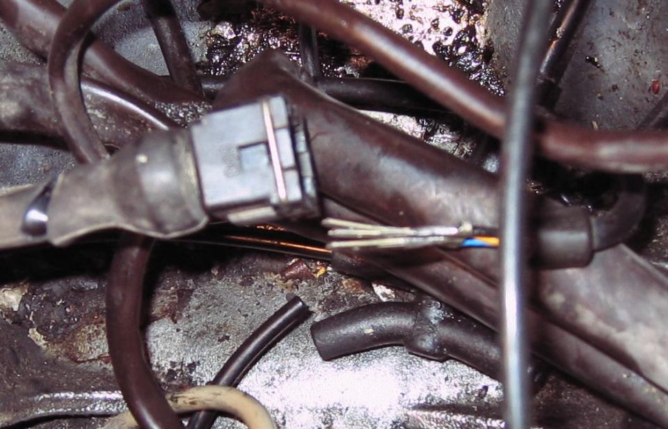
2. Same question for the Crank Position Sensor. This one has one Black, one Yellow or Orange (believe this is in the middle) and one thin black or silverish. Which side to install?
Thanks
I am un-burying this from an Intake thread I have further down in hopes someone can help me:
I have a Hall and a Crank Position Sensors whose plastic connectors disintegrated and I have not taken notes of the wires positions. Now I have new connectors to repair them, but don't know the wires positions.
The connector is asymmetrical. It has two notches on one side (thumb side in the picture) and one notch on another (indicator finger in the picture)
1. Hall Sensor (male) connector. There are three wires coming from sensor: Black, Green (middle) and Red. Which side I place the Black and which side the Red. I tried to remove the rubber part of the harness that is in its matching connector in the car to see the wires color, but it is not coming apart and will disintegrate if I try.
2. Same question for the Crank Position Sensor. This one has one Black, one Yellow or Orange (believe this is in the middle) and one thin black or silverish. Which side to install?
Thanks
 07-13-2012, 12:09 PM
#2
Rennlist Member
CPS wires are Brown, white and the last wire is a screen. Your new connector might have pin numbers written on it - if so connect white to pin 1, brown to pin 2, screen to pin 3. If no numbers, the safest course is to buzz from the cableform connector to pin 23 of EZK for the white, pin 6 for the brown and pin 24 for the screen. Then you will know what wires go where in your new plug
If you bought your 3 pin plug housing from Roger, then it has numbers on - in the view in your puicture pin one is RHS, 2 in the middle, 3 on LH . Look carefully are the wire end of the connector and you will see the numbers.
Hall sensor has Red to pin 5 EZK, Green to pin 22 & black (screen) to pin 4. Unfortunately the circuit diagram doesn't give the plug pin numbers.
 07-13-2012, 01:35 PM
#4
Rennlist Member
Thread Starter
John,
Yes, I bought the parts from Roger and I can see the tiny numbers now. Thanks for the help.
I might be looking at a different sensor; or my car has a sensor wiring that is not genuine, because the colors do not seem to match (please see pix below). I am attaching a picture showing the sensor location. It is the black one just behind the throttle cable pulley and in front of the blue tape. I might be calling this CPS and it might be something else (?)
But , if this is the CPS but has the wrong wires colors, any hint on how to place the connectors?
Thanks
07-13-2012, 03:27 PM
#6
Addict
Lifetime Rennlist
Member
Lifetime Rennlist
Member
For my 89 I replaced all female connectors (and replaced all sensors).
Looking at the connector from the front and the single notch in the middle is up and two notches on both sides are down, from left to right the wire colors are:
Knock sensors and impulse sender: black, red, white.
Hall sensor: black, white, red.
Black was what John calls a screen.
Looking at the connector from the front and the single notch in the middle is up and two notches on both sides are down, from left to right the wire colors are:
Knock sensors and impulse sender: black, red, white.
Hall sensor: black, white, red.
Black was what John calls a screen.
07-13-2012, 07:49 PM
#7
Rennlist Member
Thread Starter
Aryan & Bernard, thanks. Seems you both are in agreement
John, thanks for the help. Will work on this and check against your tips regarding connectivity at the brain. I got one repair kit here and ordering another, so I will report back as I get it done.
Many thanks
John, thanks for the help. Will work on this and check against your tips regarding connectivity at the brain. I got one repair kit here and ordering another, so I will report back as I get it done.
Many thanks
Trending Topics
09-06-2012, 08:37 PM
#8
Rennlist Member
Thread Starter

Well, have been on vacations and now came back to finish my Intake Refresh. Instead of fixing the CPS wires with a new connector, as originally planned, I decided to replace it.
Terrible mistake. Now I have a stuck bolt that I cannot remove.
I've tried liquid wrench, WD40, vise-grip, craftsman bolt-out and Irwin bolt extractor.
Disassembled the throtle cable pulley bracket to gain more access and did not help.
I saw a thread about a different extractor that attaches to the inside of the allen head (in a caliper bolt). I might have to try it tomorrow.
There are days I hate her!
09-06-2012, 08:59 PM
#9
Nordschleife Master
STOP!!!
Just drill out the head with a drill bit slightly bigger than 6mm.
If you don't you will truly screw yourself.
Once the head is off the sensor can be lifted off. Once out, heat the area and then remove with vice grips.
Just drill out the head with a drill bit slightly bigger than 6mm.
If you don't you will truly screw yourself.
Once the head is off the sensor can be lifted off. Once out, heat the area and then remove with vice grips.
09-06-2012, 09:14 PM
#10
Rennlist Member
Thread Starter
Colin,
Thanks for the tip.
My concern is if the sensor is stuck there as well and I will have no room to turn / twist it to lift and end up worse. The reason I say this is because I read some threads that - at times - this sensor is tough to pull.
But there is not much more that I can do, I guess.
Thanks for the tip.
My concern is if the sensor is stuck there as well and I will have no room to turn / twist it to lift and end up worse. The reason I say this is because I read some threads that - at times - this sensor is tough to pull.
But there is not much more that I can do, I guess.
09-06-2012, 09:27 PM
#11
Banned

Not sure about the Hall but on the CPS the only one that matters is the shield (silver). The other two, white & black or yellow & brown (what ever they are) shouldn't matter as it is an AC signal.
09-07-2012, 05:43 AM
#12
Rennlist Member
It does matter about the positions of the CPS signal wires. We had a car recently that had the CPS changed (it was faulty) but in the process a new section of CPS harness was spliced in.
The result was that the car would start, but then would cut out below about 1200rpm. It turned out the sensor wires were swapped.
The result was that the car would start, but then would cut out below about 1200rpm. It turned out the sensor wires were swapped.
09-07-2012, 06:33 AM
#13
Supercharged
Rennlist Member
Rennlist Member
Join Date: May 2002
Location: Back in Michigan - Full time!
Posts: 18,925
Likes: 0
Received 62 Likes
on
35 Posts
Colin is right. Drill the head off of the bolt. Use lots of penetrant to soak the CPS and then heat the area around the CPS. With luck it will come up and out and then you can remove the rest of the bolt.
Unfortunately with your 5-speed, there is no way to get at it from below without dropping the clutch.
09-07-2012, 09:18 AM
#14
Banned
It does matter about the positions of the CPS signal wires. We had a car recently that had the CPS changed (it was faulty) but in the process a new section of CPS harness was spliced in.
The result was that the car would start, but then would cut out below about 1200rpm. It turned out the sensor wires were swapped.
The result was that the car would start, but then would cut out below about 1200rpm. It turned out the sensor wires were swapped.
My '86 currently won't start and the last thing I did was replace the CPS connector. I'll check the wiring pinout. I had a picture of the repaired connector but I can't find it.
When you look at the signal with an O-scope it appears to "regular old AC" and neither wire is connected to the case so do you have any idea why it matters?
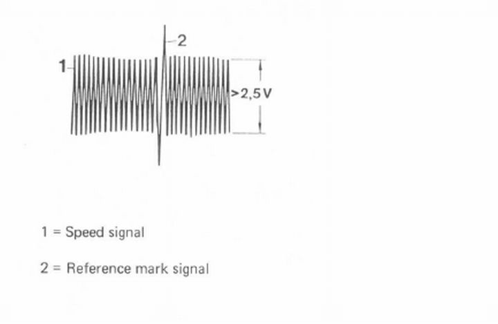
I have a video of my signal on the scope but don't know how to post it here.
Last edited by depami; 09-07-2012 at 09:52 AM.
09-07-2012, 09:26 PM
#15
Rennlist Member
Thread Starter
Well, it took me quite some effort and a lot of concern but the bolt is out.
Thanks for the tips Collin. I drilled the head (at least I tried to), and as I saw that I was not getting much better (see pix below).
So, I decided to use a manual saw to separate the sensor from the bolt head. Once that was done, I pulled the sender out and then use the vice-grip (continues to be a life saver) to rotate the bolt. I did not even have to heat it. As the sender was out, I think there has been a reduction in the bolt head tension, which might have helped.
The culprit: some blue permatex / loctite that - whoever was there before -used to lock the bolt in place. Quite honestly it seemed quite a bad idea since I don't see much happening with this area.
Anyway, pix follow:
This is another 928 10 minute job that results in few hours after all is done.
New sender is on its way.
 Thanks for the help.
Thanks for the tips Collin. I drilled the head (at least I tried to), and as I saw that I was not getting much better (see pix below).
So, I decided to use a manual saw to separate the sensor from the bolt head. Once that was done, I pulled the sender out and then use the vice-grip (continues to be a life saver) to rotate the bolt. I did not even have to heat it. As the sender was out, I think there has been a reduction in the bolt head tension, which might have helped.
The culprit: some blue permatex / loctite that - whoever was there before -used to lock the bolt in place. Quite honestly it seemed quite a bad idea since I don't see much happening with this area.
Anyway, pix follow:
This is another 928 10 minute job that results in few hours after all is done.
New sender is on its way.
Thanks for the help.
Last edited by westija; 09-07-2012 at 09:31 PM. Reason: added pictures