

speedometer odometer tachomer failure
 05-01-2012, 06:44 PM
#1
Advanced
Thread Starter

Join Date: Apr 2007
Location: Italy Mestre-Venice
Posts: 52
Likes: 0
Received 0 Likes
on
0 Posts
Hi. Today i have removed my instrument cluster because my tachometer does not work and i have found a burned resistante that seems to be related to the odometer electrical motor.
How could this have happened ? Someone can tell me the electrical value of the resistance.
I place some photo.
How could this have happened ? Someone can tell me the electrical value of the resistance.
I place some photo.
 05-01-2012, 06:50 PM
#2
Instructor
Join Date: Jan 2002
Location: Southern California
Posts: 163
Likes: 0
Received 0 Likes
on
0 Posts
I had exactly the same problem. The capacitor next to the resistor went short-circuit, which is what caused the resistor to burn out. The resistor should be 33 ohms. Be sure to check the capacitors, too.
PS: I have the datasheet for the UAF2115. If you'd like a copy, please PM me.
PS: I have the datasheet for the UAF2115. If you'd like a copy, please PM me.
Last edited by Ian S4; 05-01-2012 at 06:52 PM. Reason: added comment
05-03-2012, 07:04 PM
#4
Advanced
Thread Starter
Join Date: Apr 2007
Location: Italy Mestre-Venice
Posts: 52
Likes: 0
Received 0 Likes
on
0 Posts
I think is the capacitor circled in the next image is broken, because the capacitor have continuity ( beeeep on the meter)
But i'm not sure for the resistance (burned) value.
On the Ian's datasheet in attached seems to be 680 ohm, (resistance next to the capacitor 1NF)
If somebody have a spare speedomer it would be very useful and helpful a photo or a confirmation of the resistance value.
Another question:
how many Farad have the brown capacitor 100/16 (on the datasheet seems to be 1 nano farad ?
Last edited by biturbomax; 11-10-2012 at 08:34 AM.
05-03-2012, 07:27 PM
#5
Pro
biturbomax,
The circled capacitor is a 47 uF (microfarad) 16 volt electrolytic capacitor. The brown capacitor is a 100 uF 16 volt electrolytic capacitor. The datasheet that was provided to you contains a schematic for a test circuit for the UAF2115, but it is not the schematic for the printed circuit board in your picture. Maybe someone has this schematic handy and can post it for you.
The circled capacitor is a 47 uF (microfarad) 16 volt electrolytic capacitor. The brown capacitor is a 100 uF 16 volt electrolytic capacitor. The datasheet that was provided to you contains a schematic for a test circuit for the UAF2115, but it is not the schematic for the printed circuit board in your picture. Maybe someone has this schematic handy and can post it for you.
 05-03-2012, 07:29 PM
#6
Instructor
Join Date: Jan 2002
Location: Southern California
Posts: 163
Likes: 0
Received 0 Likes
on
0 Posts
The table in section 4.2 of the datasheet shows the values for the filter resistor (Rs = 33 ohms) and the filter capacitor (Cs = 47uF). These two components appear in the top-right corner of Figure 1 in the datasheet, next to the "+12V" pad. Porsche used 22 ohms. This is the one that burned-out. I recommend replacing both parts, with 22 or 33 ohms and 47uF or 100uF, makes little difference. The capacitor that you have circled is 47uF at 16V. You might as well also replace the brown capacitor (100uF 16V). Be sure to observe correct polarity when replacing the capacitors.
11-17-2012, 10:34 AM
#7
Advanced
Thread Starter
Join Date: Apr 2007
Location: Italy Mestre-Venice
Posts: 52
Likes: 0
Received 0 Likes
on
0 Posts
I finally repaired the speedometer.
I replaced
2 capacitor
1 restance
UAF2115 chip (buy in e-bay) http://www.ebay.it/itm/2PCS-IC-UAF21...item3a74d8055e
however, I would like to say that my speedometer only worked when I replaced the 22 ohm resistor with a 33 ohm resistor
I saw a photo on the forum pelican parts of the circuit of the speedometer and the resistance that was burned on my speedometer and after I replaced it again (22 ohm resistor) with a 33 ohm resistor.
This is the link of the photo that helped me.
http://forums.pelicanparts.com/porsc...edo-sucks.html
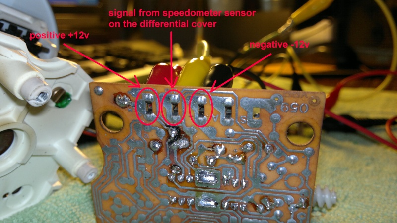
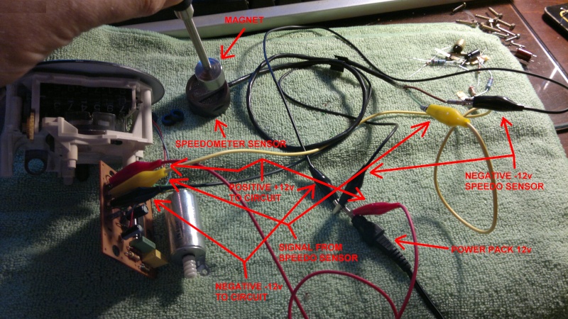
And i tested the spedometer in this simple way with a 12v power pack and a magnet (moved fast up and down near the speedo sensor if the speedo work you must see the lancet move)
I replaced
2 capacitor
1 restance
UAF2115 chip (buy in e-bay) http://www.ebay.it/itm/2PCS-IC-UAF21...item3a74d8055e
however, I would like to say that my speedometer only worked when I replaced the 22 ohm resistor with a 33 ohm resistor
I saw a photo on the forum pelican parts of the circuit of the speedometer and the resistance that was burned on my speedometer and after I replaced it again (22 ohm resistor) with a 33 ohm resistor.
This is the link of the photo that helped me.
http://forums.pelicanparts.com/porsc...edo-sucks.html
And i tested the spedometer in this simple way with a 12v power pack and a magnet (moved fast up and down near the speedo sensor if the speedo work you must see the lancet move)
Trending Topics
11-17-2012, 10:40 AM
#8

Thanks for that write up, further shows we have some really smart people here.
03-17-2019, 08:08 PM
#9
1st Gear

Join Date: Mar 2019
Location: midlands uk
Posts: 1
Likes: 0
Received 0 Likes
on
0 Posts
hi all sorry for adding or hijacking this thread
but does any one know how to wire up the motor on the very first lot of pictures , i have a 944 86 and am struggling to get my speedometer to work i have been doing bit of google searches and came across where i am now. im on the tipc forum and Porsche gb forum but cant seem to fing a write up like this
I have to date got a new sender unit fitted, tried to the best of my ability to trace the signal wire from the back to the front but loose it in the foot well, got a 2nd hand cluster ? don't know if it works in the car now but not moving, replaced cog wheel on my original speedometer and now in the process of changing the capacitors on my original speedometer to see if that's the problem but wonder if i can wire the motor up to see if it turns i can then cross out the motor not working , in all honestly its stopping me driving my car as i don't like the thought of putting to many miles on it in case i ever sell it and the mileage will be out mind you it on 150000 or there about
any help will be most welcome