

Back to square one with the GTS race motor. Arghhh! Help needed...
 03-12-2011, 02:23 AM
#61
Rennlist Member
Thread Starter
Because on my particular engine you can actually see the liners protruding from the cylinder wall into the crank case. Also Porsche AG have confirmed finally that this engine was an experiment whether they can reduce oil consumption by fitting a liner with a slightly different composition from the alusil of the block - oil will "stick" on it differently - and by fitting Kolbenschmidt pistons with four of the eight holes drilled by the factory. The other thing confirming the liners is the hand re-stamping of the tolerance group on the block from 1 to 2.
 03-12-2011, 07:16 PM
#64
Rennlist Member
Thread Starter
P.S. Their experiment worked - the engine did not use any oil when it was wet sumped and even less when it was dry sumped
03-12-2011, 07:43 PM
#65
Rennlist Member
Mark, your pictures sure help. They do show a distinct difference in finish on the top of the cylinders from the inside to the outside of the top surface. What they don't show is the line between the cylinder and the liner, which carburator's pictures show.
03-12-2011, 08:13 PM
#67
Rennlist Member
Jerry Feather
03-13-2011, 06:49 AM
#68
Alex why dont you use the block from your GT (or another good used block from an S4/GT)....much cheaper and GTS bits can all be swapped over? Will also mean you get some racing this year.
Adrian
Adrian
03-14-2011, 03:30 AM
#69
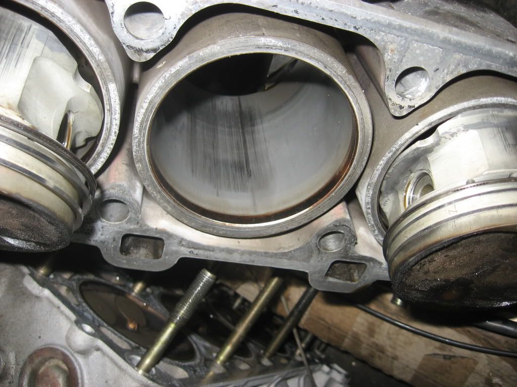
Pictures of the damage
Cylinder Nr 2 with the alusil liner...
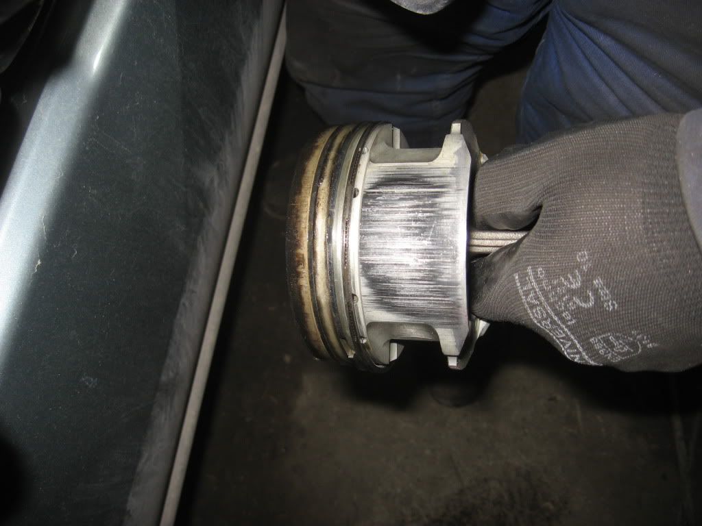
Piston Nr 2 does not look coated to me...
On a slightly better note:
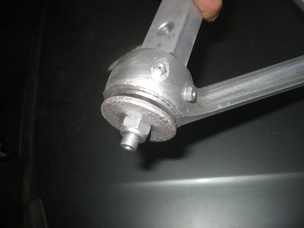
Upper A-arm with an offset pin, which shortens it by 8mm in relative terms to the lower arm, thus aleviating the need to mix and match early and later styles to achieve camber greater than -2deg 30

Details of the rose-joint
Rear control arm
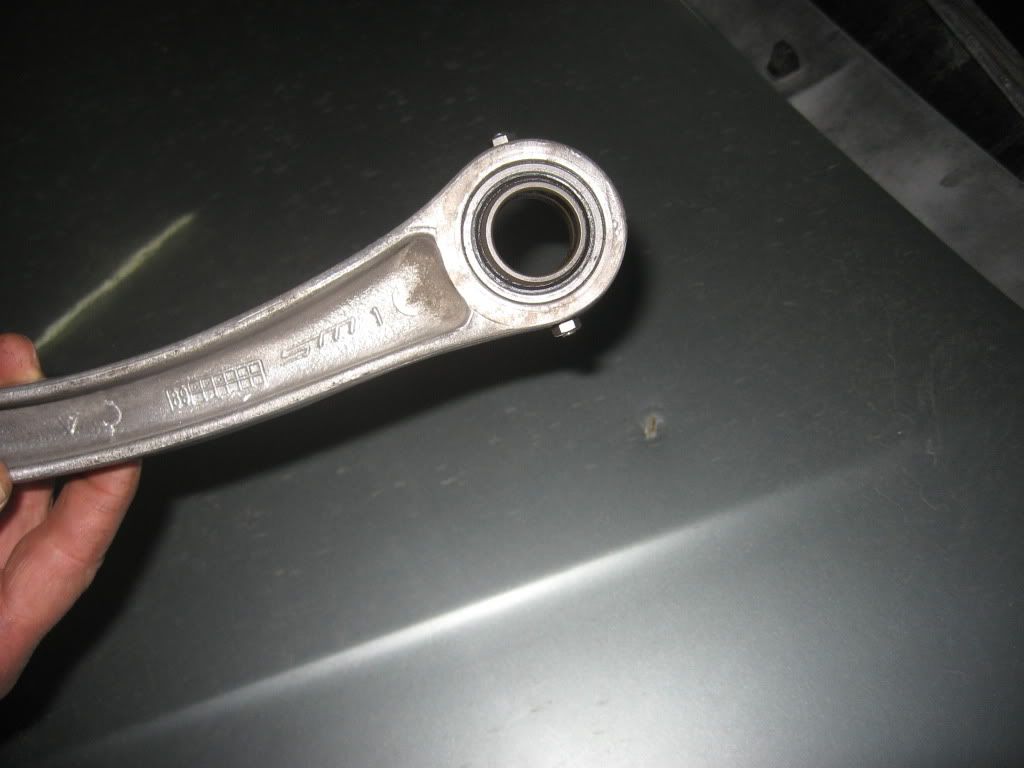
The rose-joints are fully rebuildable and utilse SKF/Russian bearings
Goes to show that we can get some things right too on this side of the pond...
Cylinder Nr 2 with the alusil liner...
Piston Nr 2 does not look coated to me...
On a slightly better note:
Upper A-arm with an offset pin, which shortens it by 8mm in relative terms to the lower arm, thus aleviating the need to mix and match early and later styles to achieve camber greater than -2deg 30
Details of the rose-joint
Rear control arm
The rose-joints are fully rebuildable and utilse SKF/Russian
bearingsGoes to show that we can get some things right too on this side of the pond...
Hard to tell how deep the scoring is from the pics but it looks like just lapping the block would fix it. Also if possible you could wet and dry the pistons and get a new moly style skirt coating and away you go. I would look at the top ring gap and get Total Seal to make me new ones to a suitable clearance. Moly coating is used by Swain etc to build up skirts of damaged engines, that will be a lot cheaper than any other option.
Greg
03-14-2011, 03:55 AM
#70
I think my idea for the OP using 944S2 pistons was with the GTS crank and not for the stroker idea. Now, I have to wonder if the 5.9 or 6L bored to 104 GTS engine will still fit the race rules??? If so, I still think that would be the bee's knees. And, if the 944S2 pistons will work, we are about half way there, aren't we? Well, not half, but some progress!!! All the OP will need is the block and rods. The rods may take a while, but not to next summer for sure.
Jerry Feather
Jerry Feather
As for cylinder thickness, F1 engines, which use a variety of different construction methods, always aluminium blocks, super light weight use no more than 3 mm wall material. Most have a pressed in steel liner but not all that 3 mm is steel. They have around 90 hp per cylinder. So a 1/4 inch seems reasonable in terms of all alloy material. The whole V10 used to weigh 95 kgs and is super complex. So it is quite thin to make that weight, interestingly the first part to fail when they started extended the milage was the blocks. So for me, the thicker the better and the parts inside the lighter the better. So those old style parts (944 S2) are not for me.
Greg
03-14-2011, 11:22 AM
#71
Rennlist Member
Thanks Greg for you input. Another thought I heard a while back was to use something like 4.1 inch pistons or something like that in inches. This would make the rings a lot cheaper.
Your thoughts on the cyl wall thickness are useful. One knowledgable source who has built strokers said that 104 would be the limit and that even 104.5 would be to big of a bore.
On the other hand, what you said about 3mm wall thickness catches my atttention. Not that I hope to go any larger thatn 104mm, but it tell me something about the strength of the material at that thin of a wall.
I think that tends to coincide with the OP's pictured cylinders with some form of Alusil liners. What appears from the pictures is that the wall thickness of the cylinders cast into the block after boring out for the liners is only about half of the original wall thickness. That is probably about 4mm thick. Then, intuitively, I would think that the liners were shrunk in the bores. If so, that means that the cylinder itself is in tension and the liner is in compression. I don't have any idea how much forse that is taking when they are stable, but it tells me that the cylinder is holding in the pressure from the liner; and then when there is combustion, the cylinger is also holding the pressure in while the liner is holding very little of it, perhaps until it expands enough to convert from compression to tension. Even then it is holding much less of the total and the thin cylinder is holding quite a bit of total pressure.
All of this tells me that the material must be pretty tough, and that 5mm or even 5.5mm will be a suitable wall thickness for a stroker bored to 6.5L.
Thanks for the heads-up on the crank. Fortunately I have kept my ear to the ground on this and have been able to accumulate two stroker cranks for reasomable cost. One is the one with 8 counterweights and the other is a 6 counter weight crank from Scat. Both are in new or like new condition.
Jerry Feather
03-14-2011, 11:54 AM
#72

I think that tends to coincide with the OP's pictured cylinders with some form of Alusil liners. What appears from the pictures is that the wall thickness of the cylinders cast into the block after boring out for the liners is only about half of the original wall thickness. That is probably about 4mm thick. Then, intuitively, I would think that the liners were shrunk in the bores. If so, that means that the cylinder itself is in tension and the liner is in compression. I don't have any idea how much forse that is taking when they are stable, but it tells me that the cylinder is holding in the pressure from the liner; and then when there is combustion, the cylinger is also holding the pressure in while the liner is holding very little of it, perhaps until it expands enough to convert from compression to tension. Even then it is holding much less of the total and the thin cylinder is holding quite a bit of total pressure.
Jerry Feather
Jerry Feather
1. A step in the liner at the top, 4.5mm in depth - below that 4.5mm depth the liner is 2 mm thinner than at first glance from the top would suggest, hence the original material is 2mm thicker than would appear at first glance (I think that was correctly noted previously in this thread?)
2. The liner is also described as having "...extremely thin walls...". So thin in fact that "...they may be subject to dimensional changes in unstressed condition, such as oval deformation, but when installed, after the shrinking process, they will again revert to the cylindrical shape of the base bore."
HTH
Last edited by daveo90s4; 03-14-2011 at 01:12 PM.
03-14-2011, 08:08 PM
#73
Rennlist Member
About the sleeving: - Kolbenschmidt's document entitled "Reconditioning of Aluminium Engines" describes the sleeving process very nicely, with step by step instructions, commentary and pictures. A few key points to note include:
1. A step in the liner at the top, 4.5mm in depth - below that 4.5mm depth the liner is 2 mm thinner than at first glance from the top would suggest, hence the original material is 2mm thicker than would appear at first glance (I think that was correctly noted previously in this thread?)
2. The liner is also described as having "...extremely thin walls...". So thin in fact that "...they may be subject to dimensional changes in unstressed condition, such as oval deformation, but when installed, after the shrinking process, they will again revert to the cylindrical shape of the base bore."
HTH
Nevertheless, I think one can conclude that the only part of a sleeved cylinder that is holding anything is likely what is left of the original cylinder after it is reamed for the liner. In this case, starting with the 116mm mentioned, then subracting the 100 mm bore, that leaves 16mm, divided by 2 is 8mm of wall thickness. If the top of the liner is about half of the total thickness, and below the top 4mm it is 2mm thinner, that would make the reamed cylinder wall right about 6mm.
If the 6mm wall will hold the pressure of combustion and the pressure of holding the liner in compression, I suspect that a cylinder wall of about 5mm minimum will still be adequate by itself as a miniumum, as also suggested in this thread.
My target is 5.5mm wall thickness because I think my cylinders are 115mm in diameter.
Thanks for the imput. It all helps.
Jerry Feather