
Purpose of resistor in coax antenna wire?
 07-12-2010, 11:42 PM
#1
Rennlist Member
Thread Starter
My troubleshooting of the utter lack of radio reception in my car led me to the head-unit end of antenna wire, as everything else checks out and/or has been replaced. It felt like there was a break in the wire where it meets the connector, so I started pulling things apart and found that there is a small resistor in the male coax connector. Imagine my surprise. You can find it if you bend out one of the free metal tabs on the coax connector.
The resistor is in-line between the center filament in the plastic tube and the pin on the male connector. It looks fried, as there is a bit of what looks like brown bubbly goo on the end that connects to the wire (it's not a liquid anymore), and the resistor post on that side looks rusted. I do not have a multimeter handy (it's on the boat right now, which has much more serious electrical problems right now!) so I cannot test it, but clearly something is wrong with it and this would explain why it's not working.
I have taken a two-pronged approach to fixing this - I ordered some male coax connectors, as well as a powered hide-it-in-the-dash FM-only antenna wire to bypass the whole mess.
If I can sort out this resistor situation, and find a new one, I will try to wire it into the new connector so I keep things as God and Porsche intended. If not, I'm going to go with the hide-away antenna wire. I have NO INTEREST in removing my entire interior to replace the coax antenna wire with a new one - so don't bother suggesting it. Please. Really. Try to resist...
My search for "antenna resistor" yielded only one relevant thread from a different forum, but that guy just bypassed it too.
So - does anyone know why this resistor is there, and why a hide-away antenna does not need a resistor like this, even though it would seem to function just like the OEM antenna does?
 07-12-2010, 11:56 PM
#2
Rennlist Member
It's possibly an in-line capacitor not a resistor. Used for blocking DC.
Like this one: http://www.summitsource.com/linear-2...01-p-9517.html
I'm sure you could just bypass it, but to be on the safe side, you could use something like the one above. It's only $1.32.
Like this one: http://www.summitsource.com/linear-2...01-p-9517.html
I'm sure you could just bypass it, but to be on the safe side, you could use something like the one above. It's only $1.32.
07-13-2010, 05:05 AM
#3
Rennlist Member
Your observation of the 'goo' also supports it being a capacitor (electrolytic). Failed capacitors often leak 'goo' which is the dielectric paste between the plates, which gets 'cooked'. Sounds like it's just succumbed to age and heat as capacitors often do.
07-13-2010, 09:59 AM
#4
Rennlist Member
Thread Starter
It's definitely not a capacitor, unless they started making capacitors with multi-colored bands around them like this since I was a kid playing with my Radio Shack electronics kit...

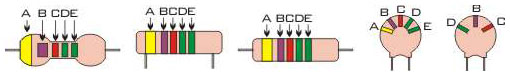
A capacitor is a very solid educated guess considering the application, but it's a definitely a resistor. It actually looks very much like the ones in this picture - the body color is a bit more yellow. I couldn't make out the band colors without an eye loupe, and I have no idea where it ended up after the move this spring. I took a couple of pictures of it last night before I started this thread, but my camera battery died as I was plugging it into the computer (and the charger is here at work).
As for the goo, it is just a residue at this point, so I wouldn't assume it was a liquid at some point. It just looks fried.
Any more ideas?
07-13-2010, 11:01 AM
#5
Rennlist Member
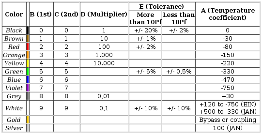
If it looks like those then it's odds on that it's a resistor.
Resistors have always been band colour coded with digits representing each colour as you go across and the final colour as a tolerance. Capacitors have almost always had a printed value and tolerance marked on them and only a few really old ones (which were bigger) were colour coded. Resistors are usually, depending on the value and wattage, able to be made a lot smaller than capacitors.
Can you post one of those pics? If the bands can be made out I can work out the value and tolerance. I'll look up one of my old electronics texts and see what I can dig up on aerial theory in the meantime and let you know what I find.
Edit: It could be that the resistor is used to 'tune' the characteristics of the specific lead/antennae combination for optimum signal and is application specific.
Last edited by Dave928S; 07-13-2010 at 11:19 AM.
07-13-2010, 11:16 AM
#6
Rennlist Member
Thread Starter
I will recharge the camera battery and d/l the pics tonight to post. My camera does not do close-up macro pics very well, so I will list the band colors, too. I know how to read them as well - I've always had a thing for that willing gal Violet for some reason.
07-13-2010, 11:49 AM
#7
Rennlist Member
Have a really good look at the connection of the resistor to make absolutely certain that it's in the signal line and doesn't link signal and earth. If it's across earth and signal it could be a 'bleed' resistor of high value to get rid of damaging higher voltage surges to earth without influencing signal.
Trending Topics
07-13-2010, 12:12 PM
#8
Rennlist Member
Thread Starter
I have taken a really good look at the connection of the resistor and I am absolutely certain that it's in the signal line and doesn't link signal and earth. 
I'll freely admit that I may occasionally post from the hip, but I do not thread-start from the hip. I exhausted my own observations, ideas and knowledge, then did additional research before starting this thread. It's a freaking stumper!! I PM'ed Alan to weigh in on the topic as well.
I'll freely admit that I may occasionally post from the hip, but I do not thread-start from the hip. I exhausted my own observations, ideas and knowledge, then did additional research before starting this thread. It's a freaking stumper!! I PM'ed Alan to weigh in on the topic as well.
07-13-2010, 01:34 PM
#9
Rennlist Member
Rennlist Site Sponsor

Sorry, Guys, but some capacitors do look just like that, including the colored bands. There is a complex color code for capacitors that may be shown by colored dots or by colored bands.
I am not a boffin, but I do think that there is more reason to have a blocking capacitor in the line than a resistor.
I am not a boffin, but I do think that there is more reason to have a blocking capacitor in the line than a resistor.
Last edited by WallyP; 07-13-2010 at 06:57 PM.
07-13-2010, 02:32 PM
#10
Addict
Rennlist Member
Rennlist Member
See Reading Part Values for more (including mica and tantalum capacitor markings).
If you have a nice DMM (like the Fluke 189 I use), you can just test the component and find out (i.e., see if it behaves like a capacitor and, if so, what its capacitance is).
07-13-2010, 03:10 PM
#11
Rennlist Member
Thread Starter
Well how 'bout that?! Who knew??
So, um, then... if it is a cap, what does it do? The link to the blocking capacitor in post #2 above says the product is used "in systems where DC and/or infrared control pulses are present on the coaxial cable." Um, like, when a 12 VDC wire runs along the length of the coax antenna wire in a 928? I know all about Gauss effects from AC current in proximity to low-voltage wiring, but I know squadoosh about antenna physics. I know I learned about it in Dr. Benofy's class at SLU, but I recall nothing.
PS - Wally, nice thinly-veiled crack on my respect for Alan's electronics expertise! Despite the jab, you've earned some respect from me with that post of yours! Thank you!
So, um, then... if it is a cap, what does it do? The link to the blocking capacitor in post #2 above says the product is used "in systems where DC and/or infrared control pulses are present on the coaxial cable." Um, like, when a 12 VDC wire runs along the length of the coax antenna wire in a 928? I know all about Gauss effects from AC current in proximity to low-voltage wiring, but I know squadoosh about antenna physics. I know I learned about it in Dr. Benofy's class at SLU, but I recall nothing.
PS - Wally, nice thinly-veiled crack on my respect for Alan's electronics expertise!
Despite the jab, you've earned some respect from me with that post of yours! Thank you!
07-13-2010, 04:33 PM
#12
Addict
Rennlist Member
Rennlist Member
Note that a capacitor can be used in an antenna system to raise its resonant frequency (read up on "capacitive loading" for more information). Capacitive loading is probably needed on the 928 due to the unusually short antenna.
I'm no antenna expert, but I think that's the purpose of the capacitor, not DC blocking. It'd be an interesting experiment to bypass it, see what happens, and then reinsert it (or a suitable replacement, if yours is defective) and see if it improves signal strength (it probably will). I'm guessing that the capacitor is an important part of tuning the antenna for optimal reception.
Then again, maybe it is just a simple protective DC blocker.
BTW, thanks for bringing up this topic... my reception has always been kind of crappy on my car; maybe I need to see if the capacitor in question is leaky and defective, too.
07-13-2010, 04:59 PM
#13
Rennlist Member
Thread Starter
That made my head hurt. But I disagree - it seems to this ignoramus that much of the discussion of capacitive loading that I found was in reference to the small antennae in mobile devices, not in cars. Compared to a cell phone, our junk is HUGE. 
It may do that though, or it may serve as a high-pass filter, or it may block interference from the 12 VDC antenna booster power supply wire, which runs parallel to the coax wire for almost its entire length.
When I get my new antenna parts, I will 1) try to put a new coax connector on the antenna wire with no capacitor, then 2) install it with a capacitor if it needs it and I can find one, and then 3) bypass the mess and use the hide-away antenna.
07-13-2010, 05:26 PM
#14
Shameful Thread Killer
Rennlist Member
Rennlist Member
That made my head hurt. But I disagree - it seems to this ignoramus that much of the discussion of capacitive loading that I found was in reference to the small antennae in mobile devices, not in cars. Compared to a cell phone, our junk is HUGE.
It may do that though, or it may serve as a high-pass filter, or it may block interference from the 12 VDC antenna booster power supply wire, which runs parallel to the coax wire for almost its entire length.
.
It may do that though, or it may serve as a high-pass filter, or it may block interference from the 12 VDC antenna booster power supply wire, which runs parallel to the coax wire for almost its entire length.
.
Your cell phone signal is in the GHz range, and the FM radio is of course 88-108MHz. Antennas come in fractional multiples of the wavelength of the transmitted wave. Usually the fractional distance of the antenna is based on the lowest frequency of reception, which has the longest wavelength in the band.
Just replace the antenna rather than try to figure out what the cap value is. Your crappy reception could also be caused by the losses in the connectors, cable, etc.
07-13-2010, 06:20 PM
#15
Still plays with cars.
Lifetime Rennlist
Member
Tuning caps are customary when the antenna is shorter than the optimal length. Cell phone antennas can be very small since the wavelength of a 1.9 GHZ signal is very short. Your AM and FM radio signals use wavelengths which are much longer. A 1/4 wave antennas for the FM broadcast band would be about 25 inches long, the AM antenna would be hundreds of feet long! The R-C circuit is used to tune the antenna electrically to improve its performance.
Best,
Best,