
Flex Plate Modification
 02-17-2010, 05:37 AM
#31
Rennlist Member
In the same spirit as Wallys post to start this thread, there is one of other possible options in dealing with the OE flexplate clamp that has intrigued me .... but I have never applied it: that option is to do exactly the reverse of firmly locking the clamp to the splined shaft.
Rather that torquing the pinch bolt to WSM spec, or the fairly common overtorque of ~65lb-ft ...... why not set it to some trivial value, say ~5-10 lb-ft? .... and before doing so, lube the splines as it were a clutch shaft. The thought is to 'pinch' the coupling into a near interference fit with the splines, but not have it so tight such that the weak restoring force of the flexplate spring fingers can be adequate to keep it in the same vertical plane as the prop shaft shortens with applied engine torque. More simply stated, just tight enough so that it doesn't chatter away like castanets, and will allow enough slip that it moves rearward on the shaft once the throttle is released and the prop shaft returns to full length - for the prop shaft is identical to a torsion bar in its behavior.
Anyway, just a little 'reverse engineering' thought to spice the discussion , for the causes/fixes to stave off TBF continues to be an entertaining topic.
In practice, I've done (Earl's) loctite 290 fix with zero movement in 6+ years on my ex-S4, and a release of the pinch bolt on other local cars at oil change intervals.
Rather that torquing the pinch bolt to WSM spec, or the fairly common overtorque of ~65lb-ft ...... why not set it to some trivial value, say ~5-10 lb-ft? .... and before doing so, lube the splines as it were a clutch shaft. The thought is to 'pinch' the coupling into a near interference fit with the splines, but not have it so tight such that the weak restoring force of the flexplate spring fingers can be adequate to keep it in the same vertical plane as the prop shaft shortens with applied engine torque. More simply stated, just tight enough so that it doesn't chatter away like castanets, and will allow enough slip that it moves rearward on the shaft once the throttle is released and the prop shaft returns to full length - for the prop shaft is identical to a torsion bar in its behavior.
Anyway, just a little 'reverse engineering' thought to spice the discussion
, for the causes/fixes to stave off TBF continues to be an entertaining topic.In practice, I've done (Earl's) loctite 290 fix with zero movement in 6+ years on my ex-S4, and a release of the pinch bolt on other local cars at oil change intervals.
 02-17-2010, 06:26 AM
#32
My motorhome is built on a 7 tonne IZUSU light truck chassis and the drive shaft is made up of 2 sections.
The forward section rotates in a bearing approximately half way along the chassis and after this bearing the forward drive shaft has a female spline and the final drive shaft has the male spline then a universal joint and at the other end another universal joint to the flange to the differential. The splines are a sliding fit and it is lubricated with a HP moly grease via a grease nipple let into the female spline assembly.
In saying this there is merit in what Garth proposes, as it totally eliviates the need for the flex plate clamp to be tightened up fully. In addition the forward flex plate operates in a relative clean environment within the bell housing and the only problem is how to lubricate the splines to ensure that there is minimal or no wear. One way could be to fit a PK type clamp fitted with two grease nipples (for balance) and a machined out groove within the ID of the clamp to allow the grease to flow around the OD of the drive shaft spline and enter the splines via the axial cuts.
The next question is who would be willing to try it ????????
Tails 1990 928S4 Auto
02-17-2010, 06:56 AM
#33
Former Vendor

Join Date: Feb 2004
Posts: 2,139
Likes: 0
Received 0 Likes
on
0 Posts
The idea of using the existing drive shaft in a loosened clamp so that it will slip will work for a bit. But the drive shaft is not properly hardend to handle this type of use and the splines will ultimately fail. Not to mention the rattling and buzzy noises that will come from using this method.
Reading through this thread I feel as if I'm in the movie "Groundhog Day"...
Reading through this thread I feel as if I'm in the movie "Groundhog Day"...
Last edited by Black Sea RD; 02-17-2010 at 08:50 AM.
02-17-2010, 07:25 AM
#34
Former Vendor
Join Date: Feb 2004
Posts: 2,139
Likes: 0
Received 0 Likes
on
0 Posts
Wally,
I would like to understand what problem you are trying to solve. As far as I can determine there has NEVER been a thrust bearing failure on any 928 that has had one of the three known fixes for the problem. 1) LOCTITE, 2) PKclamp, 3) Constantines clamp.
It seems that if the clamp can't move, then the thrust bearing can get enough lube to not wear and the flex plate has enough flex.
Most cars that have had 1 of the above fixes installed have probably had other good procedures applied also like the torque converter bearings replaced.
The only thrust bearing failure that I worked on had so many things wrong with the drive line that it was impossible to determine the cause of failure. It would be interesting to know if Porsche's assessment was actually correct. (Mechanic induced)
1. Super Clamp aka Constantine's Clamp
2. Everything else
 02-17-2010, 07:28 AM
#35
Constantine,
Good point, however to further the discussion, the migration of the flexplate clamp reaches it furtherest migration point when the draw back force overcomes the frictional force exerted by the clamp is finally overcome by the spring force exerted by the flex plate in the aft direction. At this point the flexplate clamp starts to oscillates around this point (approximately 3mm forward of the flex plate unloaded position). Wear will occasion around this point on the splines and the frictional force exerted on the splines will degenerate allowing more fore and aft movement axially along the splines if there is no failure of the thrust bearing. In fact it could occasion that the flex plate clamp may wear the splines over time until the flex plate returns to the unloaded positon. This is at a similar condition as put forward by Garth.
The question is therefore, if the splines were lubricated how long would it take for the wear to occasion. This is an unknown quantity.
The next question is would it be worth heat treating the flexplate splines and the drive shaft splines to reduce the wear rate.
In my technical opinion I would not like to attemp to do this and I believe that the hypothisis that Wally P has put forward would be a much simpler exercise to releive the extent of the maximum axial forces on the thrust bearing. However in saying this, for the sake of this discussion, I do not believe that there has been a thrust bearing failure with your super clamp, the PKclamp, any other type of clamp fitted or locktite.
If the clamp was adjusted to just "nip" the splines, then the wear would only occasion from the axial movements in the unloaded flex plate position.
Tails 1990 928S4 Auto
02-17-2010, 10:20 AM
#37
Addict
Rennlist Member
Rennlist Member
Thinking along the lines of the original post (and not discounting all the later posts praising the virtues of better shaft clamps)...
Make each of the three "ears" on the flex plate hinged.
Make each of the three "ears" on the flex plate hinged.
02-17-2010, 10:54 AM
#38
Racer
Join Date: Feb 2009
Location: Kuala Belait, Brunei
Posts: 258
Likes: 0
Received 0 Likes
on
0 Posts
Constantine,
Do you have procedures(PDF files) on installing your Super clamp? I may not need it now(My car has less that 1k Miles) but will i know I need it done near future.
Z
Do you have procedures(PDF files) on installing your Super clamp? I may not need it now(My car has less that 1k Miles) but will i know I need it done near future.
Z
02-17-2010, 11:59 AM
#39
Former Vendor
Join Date: Feb 2004
Posts: 2,139
Likes: 0
Received 0 Likes
on
0 Posts
02-17-2010, 12:38 PM
#40
Burning Brakes
3 years and 30,000 kms later Constantines clamp has proven its worth to me......through DE's and generally spirited driving.....my previous engine sits like a lump in my garage as a testament to the poor design/P/O's lack of knowledge. I drop the housing plate each spring to find that the drive shaft has migrated ZERO from the time i installed it along with the new engine....it looks like Porkens solution is similar so why reinvent the wheel?
02-17-2010, 01:35 PM
#41
Chronic Tool Dropper
Lifetime Rennlist
Member
Lifetime Rennlist
Member

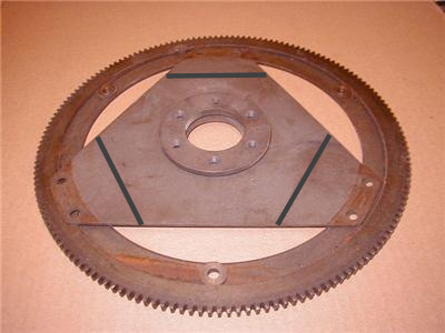
For those thinking that keeping the factory clamp loose is a solution akin to sliding driveshaft couplings, take a look at the shapes of the splines. The 928 shaft coupling has V-shaped splines, while driveshaft sliding couplings have square-shouldered splines. Applying rotational force to the 928 coupling causes the sleeve and clamp to try to expand off the shaft. The splines will wear very quickly on the drive faces of both parts even if there is no axial movement. A larger sleeve, fit over the current splines and clamped in place, with square-shouldered splines on the outside, needs to mate with a female section afixed to the drive plate. Lube it up and let it slide axially, with the rotating force born by the square spline faces.
Constantine's clamp adds a lot of clamping around the full contact area of the splines, keeping the coupling fully engaged under hard load, and is the best and most elegant solution. Contrast with the factory piece that squeezes on maybe a third of the splines. Ken's solution adds to maybe 2/3 if the clamp is installed with the splits perpendicular to the split on the factory clamp.
Constantine's clamp adds a lot of clamping around the full contact area of the splines, keeping the coupling fully engaged under hard load, and is the best and most elegant solution. Contrast with the factory piece that squeezes on maybe a third of the splines. Ken's solution adds to maybe 2/3 if the clamp is installed with the splits perpendicular to the split on the factory clamp.
02-17-2010, 02:03 PM
#42
Former Vendor
Join Date: Feb 2004
Posts: 2,139
Likes: 0
Received 0 Likes
on
0 Posts
Did this too and have pictures of this assembly. Did not work since the drive shaft, not being pinned to the back of the crank shaft as the five speed drive shaft is, let the whole assembly vibrate. Very noisy and eventually the coupler would have beat itself up under constant use.
Was also much more expensive to make and just as difficult to install as the current Super Clamp which was the last idea after this two part coupler failed our running tests.
Came full circle that the simplest and best solution was to just make a much better clamp than the original.
02-17-2010, 03:20 PM
#43
Racer
There is still one more option, very similar to Porken's clamp:
http://jenniskens.livedsl.nl/Technic...8/MyTip818.htm
No more movement and a relatively easy install.
We tried to come up with a more flex solution, but the calculations on the hardened steel of the current flexplate made us reconsider.
http://jenniskens.livedsl.nl/Technic...8/MyTip818.htm
No more movement and a relatively easy install.
We tried to come up with a more flex solution, but the calculations on the hardened steel of the current flexplate made us reconsider.
 02-17-2010, 04:27 PM
#45
Drifting
Obviously the SuperClamp is the ultimate solution. But there's no reason why a sliding coupling wouldn't work. The most extreme and impractical way to achieve this would be to replace the flex plate with a clutch pack, although presumably you would also need to replace the torque tube. I'm not advocating that, just saying that it would work.