

Resurrecting the porting and polishing by committee thread?
 06-27-2009, 07:41 PM
#46
Tuomo it sounds like you catch on real quick, so I take it that the info you bought has helped in this regard or have you other sources?
That is spot on, the velocities are critical however one thing should be added until the heads are tried on a variety of different engines none of us will know what these numbers are worth in terms of improvement or otherwise.
Tuomo if you have not increased the csa of the intake or exhaust port most generally you will be a winner and maybe a pretty big one too, as you know going to bigger valves has its risks as sometimes the valve's efficiency can fall despite it flowing more air. The fact that you haven't means good things for you. With the extra exhaust flow on say a standard engine you may actually lose power as the engine may not need so much cam duration. For your engine I am quite certain it is good if not great.
Generally I agree with your other observations, I think the 928MS port could benefit from having the floor filled to make up or decrease the CSA, to flow about 600 or so hp you only need a CSA of 2.10 sq"to 2.35 sq" With my 2V heads that flow 600 hp at max cam lift the CSA is 2.35 sq" and we are going to try and reduce it to around 2.15 sq" These 2V ports require a lot of R&D I'm sure the 4V require their far share too and I am sure that they came be improved further also.
Greg
These CFM numbers are not the same as hp numbers. CFM is mainly a marketing tool nowadays, since the customers appear to be dumbing the issues down quite a bit. 928MS doesn't report velocities, port CSA's, or wet flow stats etc. on their page. These would give a more complete picture of the performance of these heads. Carl, how about adding those data to the porting page?
Tuomo if you have not increased the csa of the intake or exhaust port most generally you will be a winner and maybe a pretty big one too, as you know going to bigger valves has its risks as sometimes the valve's efficiency can fall despite it flowing more air. The fact that you haven't means good things for you. With the extra exhaust flow on say a standard engine you may actually lose power as the engine may not need so much cam duration. For your engine I am quite certain it is good if not great.
Generally I agree with your other observations, I think the 928MS port could benefit from having the floor filled to make up or decrease the CSA, to flow about 600 or so hp you only need a CSA of 2.10 sq"to 2.35 sq" With my 2V heads that flow 600 hp at max cam lift the CSA is 2.35 sq" and we are going to try and reduce it to around 2.15 sq" These 2V ports require a lot of R&D I'm sure the 4V require their far share too and I am sure that they came be improved further also.
Greg
 06-27-2009, 08:44 PM
#47
Nordschleife Master
I think porting is like finding Rob Edwards house with Google maps, the flow bench can get you to the right neighborhood, but you still need to manually look for the driveway with the 928 in it. Dry fixed vacuum flow rates on a bench need to be seen as "tools" that in expert hands may get you more real flow, but nobody seems to know for sure until the motor is on a dyno.
Seems to me once you get past the point of porting to "general principals", what you need are many small changes with dyno runs between them, not big steps.
Seems to me once you get past the point of porting to "general principals", what you need are many small changes with dyno runs between them, not big steps.
06-27-2009, 08:59 PM
#48
Nordschleife Master
Thread Starter
Last week, I was brainstorming with a fellow rennlister about a head porting product. Take a 928 head, cut it in four pieces with one cylinder each. Sell the individual cylinder sections of the head to people who want to experiment with porting but don't have and don't want to buy full heads for experimentation. The one section would fit in the $11 flat rate USPS box. The price could probably be kept low enough for this to be an economical option for someone who wants to get his (her?) feet wet with porting experiments.
Tuomo if you have not increased the csa of the intake or exhaust port most generally you will be a winner and maybe a pretty big one too, as you know going to bigger valves has its risks as sometimes the valve's efficiency can fall despite it flowing more air. The fact that you haven't means good things for you. With the extra exhaust flow on say a standard engine you may actually lose power as the engine may not need so much cam duration. For your engine I am quite certain it is good if not great.
These heads are specifically for a 5.0 turbo engine, and I think they'll be just right for it.
Generally I agree with your other observations, I think the 928MS port could benefit from having the floor filled to make up or decrease the CSA, to flow about 600 or so hp you only need a CSA of 2.10 sq"to 2.35 sq" With my 2V heads that flow 600 hp at max cam lift the CSA is 2.35 sq" and we are going to try and reduce it to around 2.15 sq" These 2V ports require a lot of R&D I'm sure the 4V require their far share too and I am sure that they came be improved further also.
The poor availability of long-duration cams for 928 32v engine may be a good reason for increasing the valve size. To some extent, one can compensate a too mild cam by increasing the valve size. With the right cams, it looks like the stock S4 valves are the right size for a 5.0 engine.
Welding the port floor to raise the port would help any head, as long as there's enough metal on the top so the grinder doesn't catch air. There's no reason to expect my heads or 928MS heads to be an exception.
The 928 S4 heads are so good to start with that large improvements are difficult to find, unless the rest of the engine is very different from stock 928 S4. With a 5.0 normally aspirated engine, my advice would be to simply remove the casting/machining lip from the throat and save the rest of the money for an intake manifold (as BrendanC said above). For 5.0 turbo or 6.5 stroker, one can probably make significant improvements by better aligning the head characteristics with the rest of the engine.
 07-01-2009, 01:35 AM
#50
Nordschleife Master
Thread Starter
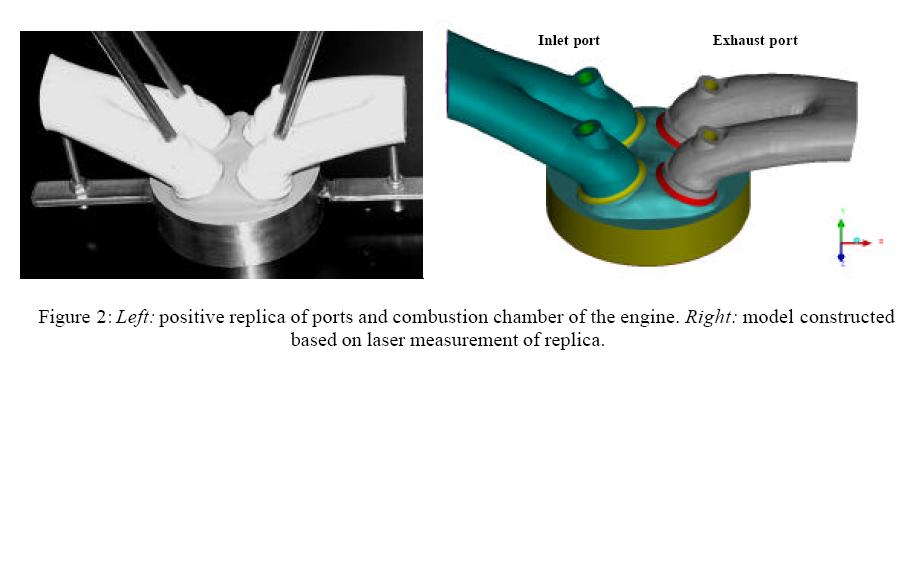
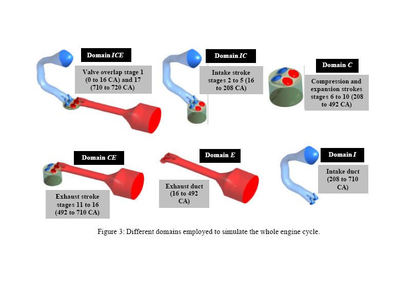
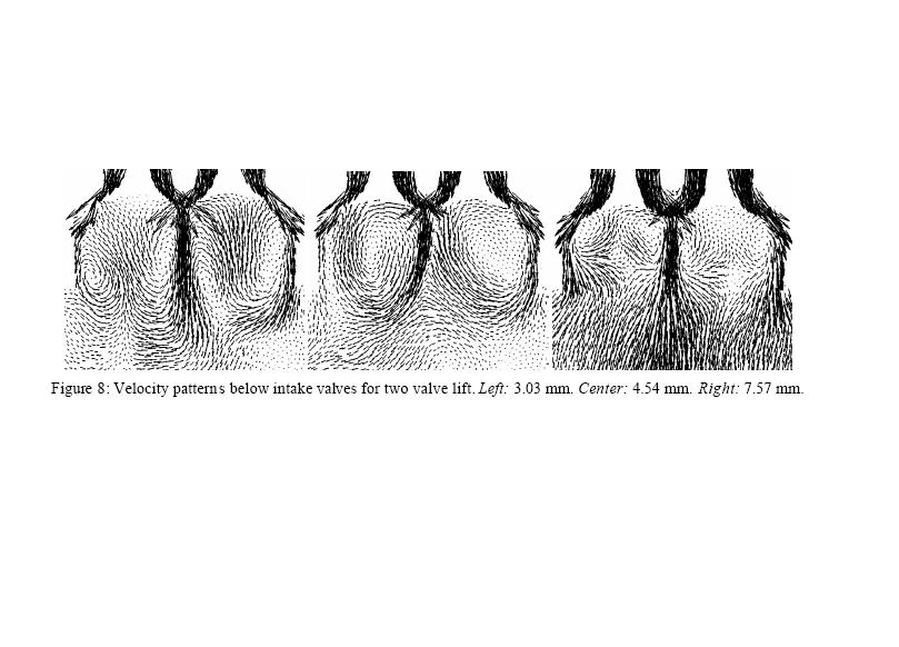
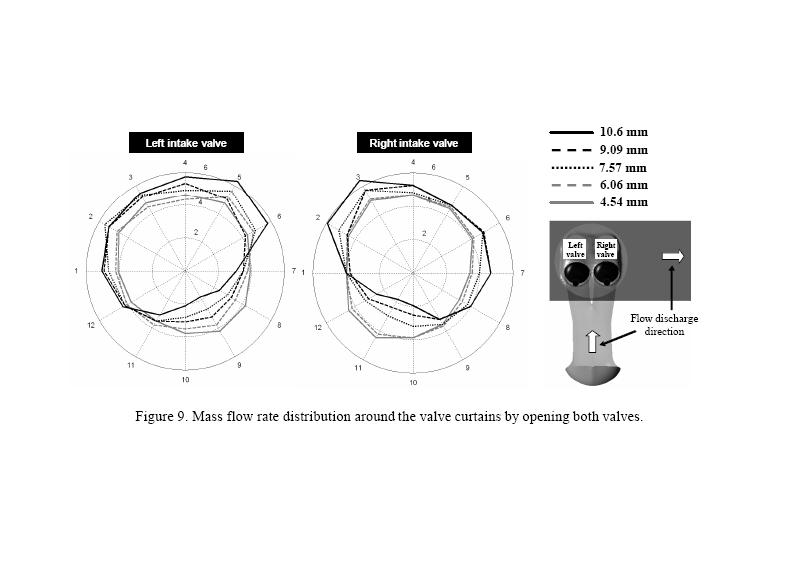
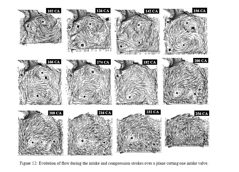
Take a look at this: http://www.cimec.org.ar/ojs/index.ph...File/1405/1370
This kind of analysis is what I think is needed to guarantee improvements from head modifications. Gorgeous graphs, too!
This kind of analysis is what I think is needed to guarantee improvements from head modifications. Gorgeous graphs, too!
07-28-2009, 04:59 PM
#51
Nordschleife Master
Thread Starter
Here's some more data on intake port flow velocities. Apologies for the f'd up decimal separators etc.
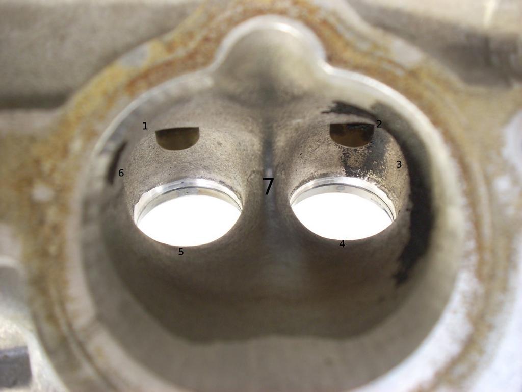
Flow is measured at 7 different positions at 6 different valve lifts in a flow bench with the standard test pressure. As always, the measurement levels are hard to compare across setups, but the comparison between RMI ported and stock heads should be reasonably valid.
Positions are clocked as follows:
#1 is the top of the left port runner about 11:00 o'clock
#2 is top of right port runner about 1:00 o'clock
#3 is the side of the right port runner about 3:00 o'clock
#4 is the bottom of the right port runner at 6:00 o'clock
#5 is the bottom of the left port runner at 6:00 o'clock
#6 is at 9:00 o'clock on the left port runner
#7 is directly in the middle of the port.
Graphical illustration attempt in 2d:
Here's the raw data table:
RMI Position
FPS 1 2 3 4 5 6 7 Average
Lift 0,10 24,00 23,60 23,00 22,60 22,80 26,60 24,90 23,93
0,20 53,50 53,30 59,30 50,20 50,60 56,30 59,40 54,66
0,30 83,20 87,80 107,10 82,30 80,50 100,10 98,60 91,37
0,40 100,10 102,60 112,90 103,80 110,60 121,10 114,10 109,31
0,50 105,30 108,20 129,60 104,00 109,80 125,40 116,40 114,10
0,60 108,30 110,10 131,40 106,10 113,50 129,70 117,70 116,69
Average 79,07 80,93 93,88 78,17 81,30 93,20 88,52 85,01
Stock Position
FPS 1 2 3 4 5 6 7 Average
Lift 0,10 0,00 0,00 27,60 22,30 22,90 27,30 24,00 17,73
0,20 40,00 52,90 47,80 48,00 42,40 59,50 50,20 48,69
0,30 78,80 74,60 102,60 77,00 83,90 97,30 80,80 85,00
0,40 86,90 89,10 117,40 80,10 94,70 110,60 89,20 95,43
0,50 86,90 108,50 128,00 91,30 96,60 118,60 101,20 104,44
0,60 98,30 96,30 124,00 85,90 100,10 111,30 103,10 102,71
Average 65,15 70,23 91,23 67,43 73,43 87,43 74,75 75,67
What's the point of these data? The below charts show the uniformity of the flow at different spots at different lifts. It's good to have even flow rate at various parts of the port (I've been told). Therefore, flatter the lines the better:
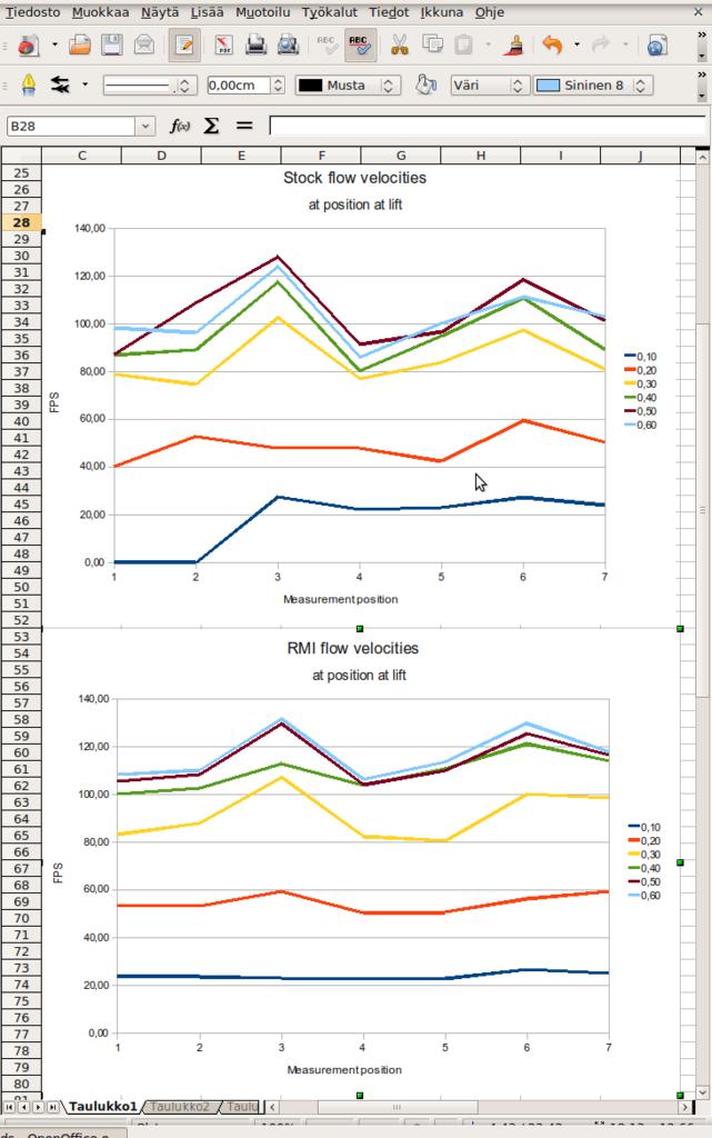
The modified port has flatter lines, and thus should be better.
It's also clear from the graphs that not much happens when one lifts the valve above 0.400", given the stock 37mm intake valves.
Flow is measured at 7 different positions at 6 different valve lifts in a flow bench with the standard test pressure. As always, the measurement levels are hard to compare across setups, but the comparison between RMI ported and stock heads should be reasonably valid.
Positions are clocked as follows:
#1 is the top of the left port runner about 11:00 o'clock
#2 is top of right port runner about 1:00 o'clock
#3 is the side of the right port runner about 3:00 o'clock
#4 is the bottom of the right port runner at 6:00 o'clock
#5 is the bottom of the left port runner at 6:00 o'clock
#6 is at 9:00 o'clock on the left port runner
#7 is directly in the middle of the port.
Graphical illustration attempt in 2d:
Here's the raw data table:
RMI Position
FPS 1 2 3 4 5 6 7 Average
Lift 0,10 24,00 23,60 23,00 22,60 22,80 26,60 24,90 23,93
0,20 53,50 53,30 59,30 50,20 50,60 56,30 59,40 54,66
0,30 83,20 87,80 107,10 82,30 80,50 100,10 98,60 91,37
0,40 100,10 102,60 112,90 103,80 110,60 121,10 114,10 109,31
0,50 105,30 108,20 129,60 104,00 109,80 125,40 116,40 114,10
0,60 108,30 110,10 131,40 106,10 113,50 129,70 117,70 116,69
Average 79,07 80,93 93,88 78,17 81,30 93,20 88,52 85,01
Stock Position
FPS 1 2 3 4 5 6 7 Average
Lift 0,10 0,00 0,00 27,60 22,30 22,90 27,30 24,00 17,73
0,20 40,00 52,90 47,80 48,00 42,40 59,50 50,20 48,69
0,30 78,80 74,60 102,60 77,00 83,90 97,30 80,80 85,00
0,40 86,90 89,10 117,40 80,10 94,70 110,60 89,20 95,43
0,50 86,90 108,50 128,00 91,30 96,60 118,60 101,20 104,44
0,60 98,30 96,30 124,00 85,90 100,10 111,30 103,10 102,71
Average 65,15 70,23 91,23 67,43 73,43 87,43 74,75 75,67
What's the point of these data? The below charts show the uniformity of the flow at different spots at different lifts. It's good to have even flow rate at various parts of the port (I've been told). Therefore, flatter the lines the better:
The modified port has flatter lines, and thus should be better.
It's also clear from the graphs that not much happens when one lifts the valve above 0.400", given the stock 37mm intake valves.
07-30-2009, 03:58 AM
#52
Nordschleife Master
Thread Starter
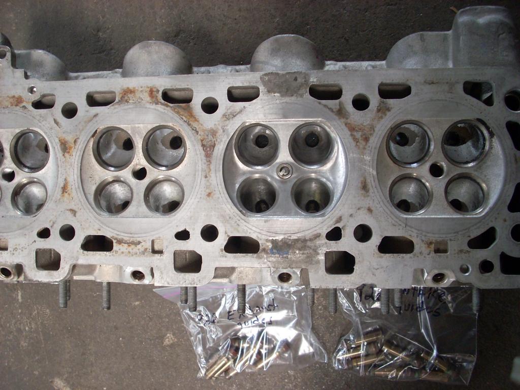
Here are some photos of test holes drilled into the head to improve cooling. These are based on the cooling modifications that Porsche incorporated to the fifth casting revision heads with casting number .5R, aka "the GTS cooling mod." The holes in the photos are drilled with 1/4 inch bit and the guinea pig is a .1R R&D head. The good heads are .4R's, one generation short of receiving these (or something like it) at the factory.
What do you think? Should we drill these to the good .4R heads as well?
What do you think? Should we drill these to the good .4R heads as well?
07-30-2009, 05:28 AM
#53
Tuomo look how similar the 928 port could be made to be like the F1 Cosworth port. We could fill the port and then cnc it to spec.


Also I would turn down the guides at the point they come into the head. Most performance don't have the guides in the port.
Greg
Also I would turn down the guides at the point they come into the head. Most performance don't have the guides in the port.
Greg
07-30-2009, 10:35 AM
#54
Nordschleife Master
Thread Starter
You are right, one could lift the port and make it round.
The reason why I didn't go that route is that
(1) I want to run these heads with stock manifold at least in the beginning. This necessitates an oval port shape.
(2) I want to run the stock computer with the injectors at stock location, spraying the intake valve.
I think (but do not know) that Sterling's new heads are just like what you suggest. He'll have ITB setup with the injectors moved higher upstream. Furthermore, he has a better computer with true sequential injection, which allows him to move the injectors high up and run big cams and short runners without occasionally blowing the fuel back out from some of the runners.
If I've understood this correctly, the stock batch-fire fuel computer needs some minimum runner length upstream the injector. Bigger the cams, longer this minimum upstream runner length. Perhaps I am confused.
In any case, the purpose of this head project has been primarily to deal with cooling. The performance mods have been in the "while your at it" category. I am very happy with the flow improvements, but even more happy with the cooling improvements that we're making: coatings, extra cooling passages, new valve guides, valve job, etc. For example, we'll be leaving the exhaust valve guides longer and thicker than one would usually do to make sure that valves are cooled appropriately. Another example is that the valve springs are going to be pretty stiff to minimize the valve bounce off the seat, again helping with valve cooling.
You're probably right about doing something about the guides on the intake side, which is most likely in the cards. The photo that I linked you to is the stock port, so it has the full length guides.
08-04-2009, 05:15 AM
#55
Nordschleife Master
Thread Starter
RMI exhaust port velocity in FPS:
Lift 1 2 3 4 5
100 115.0 150.2 106.5 152.0 56.6
200 326.5 279.5 100.2 286.7 254.5
300 311.7 340.3 262.9 344.0 343.3
400 311.6 339.5 287.5 349.6 334.1
500 305.0 345.9 303.9 342.3 323.8
600 302.1 355.5 292.8 352.6 332.5
Stock exhaust port velocity in FPS:
Lift 1 2 3 4 5
100 200.9 137.6 0.0 178.0 132.9
200 323.6 261.8 102.2 310.1 253.4
300 321.7 320.2 204.5 359.0 330.1
400 324.0 319.4 249.7 349.4 329.6
500 301.6 332.9 274.8 348.2 334.5
600 303.1 331.9 277.3 344.8 340.6
The measurement positions are at the round section after the two runners have combined. #1 at 12 o'clock, #2 is at 3 o'clock, #3 is at 6 o'clock, #4 is at 9 o'clock, and #5 is at the center of the port.
There are a couple of noted improvements. First, the left and right side runners were badly imbalanced at low lifts for this particular port. The modifications cured the imbalance. Second, the short radius velocity is improved dramatically at low lifts, moving some of the flow to the short side from the middle. Third, the velocities are much more even across measurement positions.
Altogether, this port should extract the exhaust gas faster from the cylinder. The cross-sectional area is very close to that of the stock port, yet the CFM flow is better and the velocities are uniformly as high everywhere.
Lift 1 2 3 4 5
100 115.0 150.2 106.5 152.0 56.6
200 326.5 279.5 100.2 286.7 254.5
300 311.7 340.3 262.9 344.0 343.3
400 311.6 339.5 287.5 349.6 334.1
500 305.0 345.9 303.9 342.3 323.8
600 302.1 355.5 292.8 352.6 332.5
Stock exhaust port velocity in FPS:
Lift 1 2 3 4 5
100 200.9 137.6 0.0 178.0 132.9
200 323.6 261.8 102.2 310.1 253.4
300 321.7 320.2 204.5 359.0 330.1
400 324.0 319.4 249.7 349.4 329.6
500 301.6 332.9 274.8 348.2 334.5
600 303.1 331.9 277.3 344.8 340.6
The measurement positions are at the round section after the two runners have combined. #1 at 12 o'clock, #2 is at 3 o'clock, #3 is at 6 o'clock, #4 is at 9 o'clock, and #5 is at the center of the port.
There are a couple of noted improvements. First, the left and right side runners were badly imbalanced at low lifts for this particular port. The modifications cured the imbalance. Second, the short radius velocity is improved dramatically at low lifts, moving some of the flow to the short side from the middle. Third, the velocities are much more even across measurement positions.
Altogether, this port should extract the exhaust gas faster from the cylinder. The cross-sectional area is very close to that of the stock port, yet the CFM flow is better and the velocities are uniformly as high everywhere.
09-02-2009, 07:12 AM
#56
Generally I agree with your other observations, I think the 928MS port could benefit from having the floor filled to make up or decrease the CSA, to flow about 600 or so hp you only need a CSA of 2.10 sq"to 2.35 sq" With my 2V heads that flow 600 hp at max cam lift the CSA is 2.35 sq" and we are going to try and reduce it to around 2.15 sq" These 2V ports require a lot of R&D I'm sure the 4V require their far share too and I am sure that they came be improved further also.
Greg
Greg
0.400" --------251 cfm
0.500"-------- 288 cfm
0.600"---------311 cfm
0.700"---------322 cfm
I did flow from 0.050" to 1" but this is just an except, and it is the most relevant part of the port given the cams will lift to 0.650" or 16.51 mm so around 315 cfm of air at peak cam lift and very high velocities will be developed as long as all the parts get along with each other.
Calculated live engine airspeed is between 700 feet per second in the low 7,000 rpms and a max of 750 FPS at 8,000 rpm, it may not like this much but the port is extremely straight and I have been highly encouraged to give it a go.
For those who are wondering why run the speed so fast, the reason is volumetric efficiency, the inertia of the air fills the cylinder beyond 100% The faster the air the better the potential is here. With the airflow quoted in the Jason Hart racecar thread, the only way that engine achieved more than 630 hp was the speed of the air in the intact tract, without the high air speed there is a formula that has been around for many years and it is roughly for every CFM of air you can get 2 HP, or 2.056 to be more precise.
Tuomo and others do you know what the CC or volume is of the S4 port? Also we need the length of the port to work out the CSA.
Greg
09-02-2009, 03:28 PM
#57
Rennlist Member
This is a great thread! 
09-02-2009, 03:55 PM
#58
Archive Gatekeeper
Rennlist Member
Rennlist Member
Tuomo and others do you know what the CC or volume is of the S4 port? Also we need the length of the port to work out the CSA.
I can of course do the same thing on the exhaust side.
I've got a whole lab of precision fluid handling/mesauring devices, y'all just tell me what you want.
09-02-2009, 05:41 PM
#59
Nordschleife Master
Thread Starter
No idea what the volume is but I have sheets of plexiglass, a buret, and a pair of GTS heads with the valves still in them. Is this simply a matter of buretting the entire intra-head intake port? Should I pull the two valves (and plug the valve guide), or can I just measure the length ('X' centimeters) of the exposed valve stem and then measure the contributing volume of the S4 intake valve itself by dipping it 'X' cm intro a graduated cylinder? I can of course do the same thing on the exhaust side. I've got a whole lab of precision fluid handling/mesauring devices, y'all just tell me what you want.
If you can seal the valve guide to valve stem small gap with vaseline and similarly get the valve to valve seat sealed, yes, I would just pour it in. I've also never done that, but it ought to work. The port volume is so commonly reported that I was surprised I didn't get google hits of how to measure it. Plus I am at work and it's embarrasing to surf google images for longer than I just did.
Another interesting measurement is to take a thin metal wire and measure the long-side and short-side lengths with it. I guess I would measure from the valve seat cut to the intake manifol gasket surface. I think the short-side and the long-side lengths are interesting on their own. The average port length I would measure just as the average of the long and short.
Another interesting stat is the minimum cross sectional area. I am guessing that this is [EDIT: right before the valve guides] or whatnot, for 928 S4-GT-GTS heads. One pushrod V8's I think it's near the pushrods, but since we don't have pusrods it _should_ be [EDIT: right before the valve guides].
[EDIT: Untrue stuff deleted. It turns out that for pent-roof four-valve combustion chambers, the MCSA has to be pretty far upstream, before the valve guides. If one doesn't let the air diffuse and slow already in the port, one loses flow. This apparently is because the four-valve combustion chamber is so open.]
Last edited by ptuomov; 09-10-2009 at 06:07 PM.
09-02-2009, 06:59 PM
#60
Nordschleife Master
Thread Starter
O.k just an update I did some flow tests and with a 2.20 sq" port CSA I achieved some nice flow numbers, as follows.
0.400" --------251 cfm
0.500"-------- 288 cfm
0.600"---------311 cfm
0.700"---------322 cfm
I did flow from 0.050" to 1" but this is just an except, and it is the most relevant part of the port given the cams will lift to 0.650" or 16.51 mm so around 315 cfm of air at peak cam lift and very high velocities will be developed as long as all the parts get along with each other.
Since you have no turbosuperdupercharger, 700 fps is a mach index of about 0.6 and 750 fps is a mach index of about 0.65. Certainly not slow! ;-) It is my understanding that the sweet spot is at .55 mach before which more speed will generate more ramming than what is lost in additional friction/turbulence/whatnot and after which more speed will lead to bigger increase in friction than what is gained in additional ramming. (It hink I read this on the internet so CAVEAT EMPTOR!) This may be for "average" port and your "straight" may be inherently less subject to friction etc.
The good news that you can always grind more metal off if the torque drops off too early... If you don't meet your goals and if the only problem is too high velocity, you'll see monster torque at mid range. You'll move that torque mountain 500 rpm to the right with a grinder in a weekend!
This of course contains no info that is both new to you and correct, since I am basically repeating to you the points that I've learned from the CD's I bought from you! ;-)
For those who are wondering why run the speed so fast, the reason is volumetric efficiency, the inertia of the air fills the cylinder beyond 100% The faster the air the better the potential is here. With the airflow quoted in the Jason Hart racecar thread, the only way that engine achieved more than 630 hp was the speed of the air in the intact tract, without the high air speed there is a formula that has been around for many years and it is roughly for every CFM of air you can get 2 HP, or 2.056 to be more precise.
I have no idea, but I'll see if I can measure those. Rob Edwards will produce more accurate numbers faster, of course...