
The Mother Of Air Box mods?
 07-07-2003, 05:49 PM
#31
Instructor

Join Date: Jan 2002
Location: Boca Raton Fl to Portland ME
Posts: 174
Likes: 0
Received 0 Likes
on
0 Posts
You said
"On my expermiment list is putting an aluminum sheet over the underside of the hood all the way up to in front of the radiator(s), perhaps then even down to below the bumper, to funnel a large amount of cooler air to the air box. My MOAB would be revised to be closed except at the top where there would be a large central opening sealing to the hood panel for a ram-air effect"
Do you mean attaching this to the hood?
or to the top of the Eng.
There seems to be some room to drop a snorkel down either
side of the box down below the engine?
Britt
 07-07-2003, 05:56 PM
#32
Rennlist Member
</font><blockquote><font size="1" face="Verdana,Tahoma,Helvetica">quote:</font><hr /><font size="2" face="Verdana,Tahoma,Helvetica"> putting an aluminum sheet over the underside of the hood all the way up to in front of the radiator(s), perhaps then even down to below the bumper, to funnel a large amount of cooler air to the air box. </font><hr /></blockquote><font size="2" face="Verdana,Tahoma,Helvetica">I think that is a great idea! I can imagine one inlet above the radiator, splitting into 2 seperate rectangular ductways, following the sides of the hood, to a custom airbox top. Essentially integrated into the hood.
Material: aluminum, polished for looks
Stronger hood shocks.
Also, the custom airbox top could also have a third duct to the cowl which could be closed when needed.
Cool, but I'm not convinced it would accomplish much, less getting rid of the unsightly stock airbox ducts.
Just brianstorming.
Material: aluminum, polished for looks
Stronger hood shocks.
Also, the custom airbox top could also have a third duct to the cowl which could be closed when needed.
Cool, but I'm not convinced it would accomplish much, less getting rid of the unsightly stock airbox ducts.
Just brianstorming.
07-07-2003, 06:13 PM
#33
Drifting
Join Date: Jul 2002
Location: Los Angeles, CA
Posts: 3,348
Likes: 0
Received 0 Likes
on
0 Posts
For those of you who had debated running the intake tubes out the hood, to the outside air, but were worried about water getting to the intake tract:
<a href="http://www.kinkyimports.com/Merchant2/merchant.mvc?Screen=PROD&Product_Code=20-401S&Category_Code=cc9295" target="_blank">Air Bypass Valves</a>
<img src="http://www.kinkyimports.com/Merchant2/graphics/00000001/airbypass2.jpg" alt=" - " />
<a href="http://www.kinkyimports.com/Merchant2/merchant.mvc?Screen=PROD&Product_Code=20-401S&Category_Code=cc9295" target="_blank">Air Bypass Valves</a>
<a href="http://www.kinkyimports.com/Merchant2/merchant.mvc?Screen=PROD&Product_Code=20-401S&Category_Code=cc9295" target="_blank">Air Bypass Valves</a>
<img src="http://www.kinkyimports.com/Merchant2/graphics/00000001/airbypass2.jpg" alt=" - " />
<a href="http://www.kinkyimports.com/Merchant2/merchant.mvc?Screen=PROD&Product_Code=20-401S&Category_Code=cc9295" target="_blank">Air Bypass Valves</a>
07-07-2003, 06:28 PM
#34
Inventor
Rennlist Member
Rennlist Member
Thread Starter
Brittany Chen Li - I considered both, but I like to see the engine when I open the hood so settled on the hood. I am still inventing the attachment method, as I don't want to drill any holes or dent the hood skin. So far I am leaning towards tabs on the edges of the panel, which would catch on the inward angled lip around the inside of the hood. The connection to the airbox would have to be thick foam, to compensate for engine rocking.
I would also put some thin heat reflective insulation facing the engine.
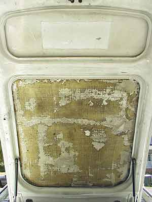 (main indent is aprox. 35"long, 28"top, 30"bottom, ~1-1/4" deep)
Jadz928 - I want one ultra-wide unrestricted duct, for maximum volume, to enhance the ram effect at the small air flow meter opening. I don't think it would be any heavier than the missing sound deadener. I too am unsure whether there would be significant gains, but who knows?
I would also put some thin heat reflective insulation facing the engine.
(main indent is aprox. 35"long, 28"top, 30"bottom, ~1-1/4" deep)Jadz928 - I want one ultra-wide unrestricted duct, for maximum volume, to enhance the ram effect at the small air flow meter opening. I don't think it would be any heavier than the missing sound deadener. I too am unsure whether there would be significant gains, but who knows?
Last edited by PorKen; 07-15-2003 at 12:22 AM.
07-07-2003, 07:30 PM
#35
Rennlist Member

Join Date: Dec 2002
Location: Southern New England
Posts: 1,975
Likes: 0
Received 0 Likes
on
0 Posts
For each 20 cfm of airflow (10 cfm per side), we see a velocity of about 40" per second. This assumes that the 3" tube has a cross section of about 7 square inches.
I am not sure what the actual intake cfm is, but it sounds unlikely that the original configuration airflow is unlikely to have time to pick up much heat from the plumbing. Just stick one of those electronic cooking thermometers on top of the air filter and compare the reading with what you get at the mouth of the intake.
On the flip side, it doesn't seem like a very restictive arrangement, either. I wouldn't expect to see a vacuum gauge connected to the top of the airbox register anything.
Has anyone ever dyno'ed their car without the air filter in place?
07-08-2003, 05:21 AM
#36
Drifting
Join Date: Feb 2002
Location: Redondo Beach, CA>>>>Atlanta,GA
Posts: 2,015
Likes: 0
Received 0 Likes
on
0 Posts
Porken...got my chips cashed in...
Nice project. I would like to see you put any time and energy you may still be using on the folding license plate, missing mirrors, or foglight projects into this one.
Will the cross brace be a hurdle for the aluminum duct?
<img border="0" alt="[cheers]" title="" src="graemlins/beerchug.gif" />
Andy K
07-08-2003, 02:57 PM
#37
Addict
Rennlist Member
Rennlist Member
Not intending to cut your creativness, but I think your results will in evidably be the same, if not worse. Aluminum will retain more heat than plastic. You will also be creating a larger area to be heated more quickly. The OEM tubes are 3" round and you will not be able to get that kind of diameter along the hood. So if you end up flattening the venting at the hood with say...about 1" by 9" of space x 2(almost equal in volume), you now have created a larger surface for the heat to radiate into, while heating the air quicker, so you may just end up with hotter air flowing into the air box.
Aside from all of this, the clearance between the hood and radiator is "0". There is (should) be a rubber seal/strip on the top edge of the radiator. You can see where the hood rests on this.
Again, you are going to have a really tough time getting cooler air from the front of the car through the engine bay. Pull it from behind the splash guards in the rear of the front fenders (behind the wheels), it's a shorter run. It would be nice to daylight them at the sides of the fenders, but this poses its own set of problems. Just getting to the inside of the fenders will be a job in itself.
So you need the shortest route, bringing in the coolest air possible while trying to excelerate it into the airbox....hmmmm <img border="0" title="" alt="[Wink]" src="wink.gif" /> I think they already make a device for this.
seriously,I think the quickest most efficient way is the cowl. You would have to rig a manual flap to keep out water, but at the same time, open up another intake area from inside the engine bay to draw dry air....not a tough rig to make.
In the end though, this has been tried and dyno'd with no significant improvements. I like the idea though!
07-08-2003, 03:18 PM
#38
Drifting
Join Date: Jul 2002
Location: Los Angeles, CA
Posts: 3,348
Likes: 0
Received 0 Likes
on
0 Posts
Or...
To increase the airflow into the intake tubes, and keep the air cooler, cut slots in the hood, and use those bypass valves to prevent any water from entering the intake. The ram-air effect has been proven successful for increased HP in motorcycles, so it would make sense that at higher speeds, the air rushing in the intake tubes from outside, would be a lot cooler that the air coming in from the radiator area...
<a href="http://groups.msn.com/socal928/devekdays.msnw?action=ShowPhoto&PhotoID=53/socal928/devekdays.msnw?action=ShowPhoto&PhotoID=53" target="_blank">http:// groups.msn.com/socal928/devekdays.msnw?action=ShowPhoto&PhotoID=53/socal928/devekdays.msnw?action=ShowPhoto&PhotoID=53</a>
Also, check out this guy's driving lights...
07-08-2003, 03:32 PM
#39
Rennlist Member
The highest air pressure zones are the nose and windshield cowl. To produce the ram air effect on the hood, you would need a scoop at least 2-3" high. There is no air pressure on the hood.
07-08-2003, 03:37 PM
#40
Addict
Rennlist Member
Rennlist Member
Brian...I took that pic at the 2001 DEVEK Days. The scoops open to the mouths of the intake tubes on top of the radiator. From previous discussions with other innovators on this subject, these scoops are worthless. This is the result of testing. Besides, most think they look like crap.
The lighting are GMC marker lights, no driving lights. They do look clean though!
As for the 2.5" valves, that site does not tell how they work, nor are there specs on flow in and out. They may be restrictive.
The lighting are GMC marker lights, no driving lights. They do look clean though!
As for the 2.5" valves, that site does not tell how they work, nor are there specs on flow in and out. They may be restrictive.
07-08-2003, 04:06 PM
#41
Drifting
Join Date: Jul 2002
Location: Los Angeles, CA
Posts: 3,348
Likes: 0
Received 0 Likes
on
0 Posts
I think the idea on those bypass valves, is that they are just a foam screen, so that if water gets in, they catch it, and it drains out the bottom. The rest of the time, the air flows past them. They will suck in some air, so they sort of act like little air cleaners. Not the ideal soloution, but better than nothing, if someone does decide to suck air directly from the outside of the car somehow...
And yes, I know those are not driving lights. They still look kind of cool...
And I agree that the intake scoops do not look so hot. But some people are more into speed than looks, and it does seem like a good way to stuff a lot more cool air into the intake... It has to be better than stock, even if it is not a huge difference.
07-08-2003, 05:45 PM
#42
Inventor
Rennlist Member
Rennlist Member
Thread Starter
Old & New - Unfortunately the factory intake tubes are only 3" part of the way, and where they are, they are not smooth inside, and they both crash into a 90deg bend with a triangular shaped transition at the airbox.
Everyone - my idea is that the air flow show be straight into the AFM for max airspeed = response.
GoRideSno...got to mellow slow... I didn't think about the brace, and it is a problem, but see below, fixed.
An unintended benifit of no air tubes: you can turn the crossbar over! (lower=better bracing?)
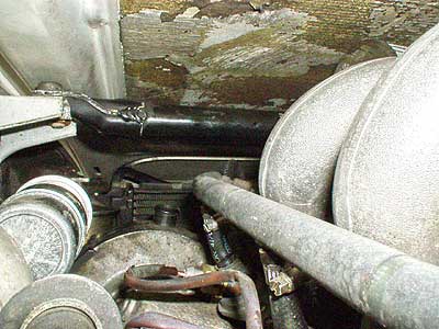
928ntslow - without the fan shroud, there is a ~2" gap above the radiator. The cowl would be easier, but I can't see how to do it without cutting.

Note the creative use of the camera self-timer...
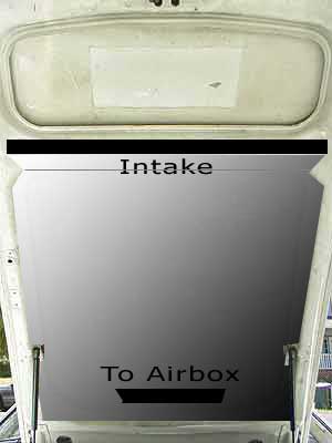
Because no-one seems to be reading") , let me reiterate, one duct (to rule them all), created by covering the void in the hood normally occupied by sound deadener, with a single aluminum (or fiberglass) panel which gives an interior cross section of a minimum, 1-1/4" x 24" = 30sq". The panel would be held in place by upward and outward facing tabs around the perimeter of the panel, which would catch on the inward and downward facing lip of the hood structure. The panel would be covered on the engine side by a refective insulating material.
, let me reiterate, one duct (to rule them all), created by covering the void in the hood normally occupied by sound deadener, with a single aluminum (or fiberglass) panel which gives an interior cross section of a minimum, 1-1/4" x 24" = 30sq". The panel would be held in place by upward and outward facing tabs around the perimeter of the panel, which would catch on the inward and downward facing lip of the hood structure. The panel would be covered on the engine side by a refective insulating material.
The panel would flare down at the radiator to fill the space normally occupied by the upper fan shroud. This would collect air from the pressurized area in front of the radiator(s).
Cold air collection could be further enhanced by having a fixed 1-1/2"x24" duct go from the top of the radiator and curve 90deg down to below the back of the bumper support to ensure cold air pickup. The duct would also be insulated. This would entail removal of the A/C fan.
A new airbox cover would be made with a large central upward facing opening, which would seal to a corresponding opening in the duct panel, sealed by ~2" foam around the perimeter of the opening.
Everyone - my idea is that the air flow show be straight into the AFM for max airspeed = response.
GoRideSno...got to mellow slow... I didn't think about the brace, and it is a problem, but see below, fixed.
An unintended benifit of no air tubes: you can turn the crossbar over! (lower=better bracing?)
928ntslow - without the fan shroud, there is a ~2" gap above the radiator. The cowl would be easier, but I can't see how to do it without cutting.
Note the creative use of the camera self-timer...
Because no-one seems to be reading
, let me reiterate, one duct (to rule them all), created by covering the void in the hood normally occupied by sound deadener, with a single aluminum (or fiberglass) panel which gives an interior cross section of a minimum, 1-1/4" x 24" = 30sq". The panel would be held in place by upward and outward facing tabs around the perimeter of the panel, which would catch on the inward and downward facing lip of the hood structure. The panel would be covered on the engine side by a refective insulating material.The panel would flare down at the radiator to fill the space normally occupied by the upper fan shroud. This would collect air from the pressurized area in front of the radiator(s).
Cold air collection could be further enhanced by having a fixed 1-1/2"x24" duct go from the top of the radiator and curve 90deg down to below the back of the bumper support to ensure cold air pickup. The duct would also be insulated. This would entail removal of the A/C fan.
A new airbox cover would be made with a large central upward facing opening, which would seal to a corresponding opening in the duct panel, sealed by ~2" foam around the perimeter of the opening.
Last edited by PorKen; 07-15-2003 at 12:24 AM.
07-08-2003, 05:49 PM
#43
Instructor
Join Date: Jan 2002
Location: Boca Raton Fl to Portland ME
Posts: 174
Likes: 0
Received 0 Likes
on
0 Posts
"The highest air pressure zones are the nose and windshield cowl." Okayt the windshield cowl can't get much closer than that. I little cut here and there, then duck it in.
Porken. Great job on the pics.
I think you have a good idea. Keep going on it you maybe on to somthing very cool.
Britt
Porken. Great job on the pics.
I think you have a good idea. Keep going on it you maybe on to somthing very cool.
Britt
07-08-2003, 06:42 PM
#44
Inventor
Rennlist Member
Rennlist Member
Thread Starter
Perhaps this el-cheapo graphic might help:
Last edited by PorKen; 07-15-2003 at 12:24 AM.
07-08-2003, 06:59 PM
#45
Instructor
Join Date: Jan 2003
Posts: 183
Likes: 0
Received 0 Likes
on
0 Posts
Don't automatically assume some of this stuff. The cowl area at the base of the windshield isn't a high pressure area on all cars. On a Lexus it's actually a low pressure area. Before you guys re-engineer everything, you might want to do some temperature and pressure measuring while at speed. The stock setup is a lot better than some of you apparently think. The area that the stock intake tube openings are located at is a high pressure area, and recieves cold air with the car in motion.