
Ground Points (per Fletch's question)
 03-27-2002, 05:39 PM
#1
Rennlist Member
Thread Starter
Join Date: Aug 2001
Posts: 502
Likes: 0
Received 0 Likes
on
0 Posts
Listed as follows in the manual:
-Battery negative to body
-Above and behind central electrical panel (2 points)
-Engine to body (under passenger's side)
-Left front cross member (to left of headlight motor)
-Right front cross member (passenger's side)
-Under instrument panel by steering column
-Under right rear side trim panel (inside)
Additionally, my fuel injection harness is grounded to bolts on the passenger's side valve cover.
 04-02-2002, 09:03 PM
#2
Addict
Lifetime Rennlist
Member
Lifetime Rennlist
Member
Hey James - thanks (on behalf of fletch).
Anuone have a pic showing the location of "-Left front cross member (to left of headlight motor) and -Right front cross member (passenger's side)" grounding points?
Can't seem to locate them on my '79, and no pic in my manuals.
Anuone have a pic showing the location of "-Left front cross member (to left of headlight motor) and -Right front cross member (passenger's side)" grounding points?
Can't seem to locate them on my '79, and no pic in my manuals.
04-02-2002, 10:29 PM
#3
Chronic Tool Dropper
Lifetime Rennlist
Member
Lifetime Rennlist
Member

No car handy to get a picture, but...
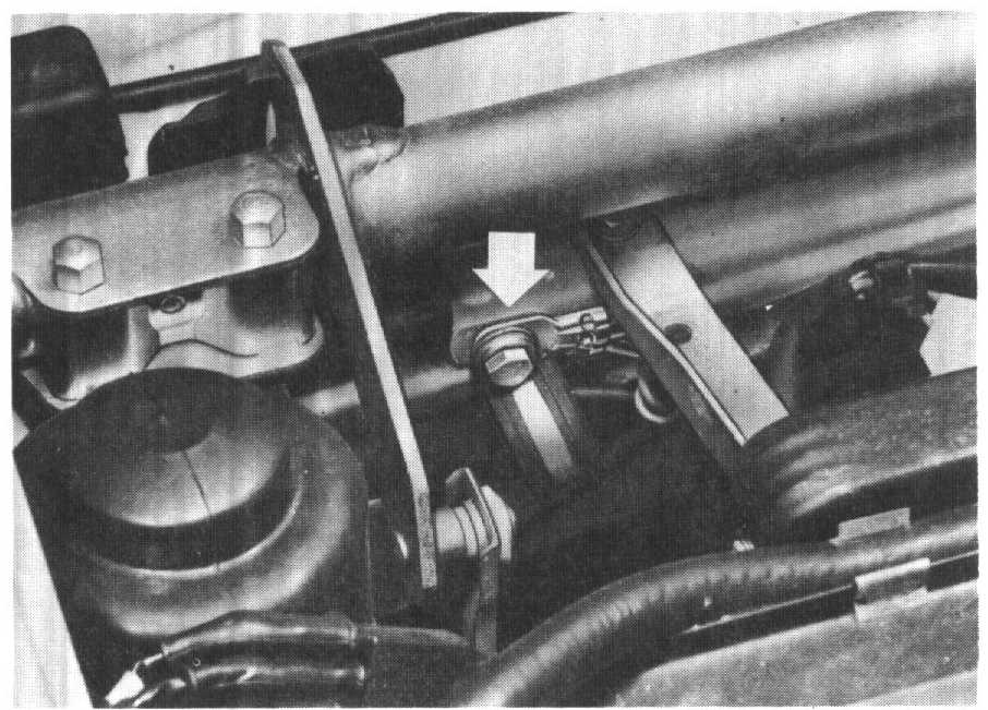
The ground points on my later car are 6mm dia/10mm hex head capscrews with a spider of brown wires with ring tongue connections on them. The "crossmember" description is poor-- they are in the corner where the top of the radiator sheet joins the body at the fender.
On the right side (passenger side on US cars) mine is easy to spot slightly above and forward of the jumpstart terminal, and next to the 14-pin sandwich connector that attaches to the car just ahead/forward of the jumpstart terminal block.
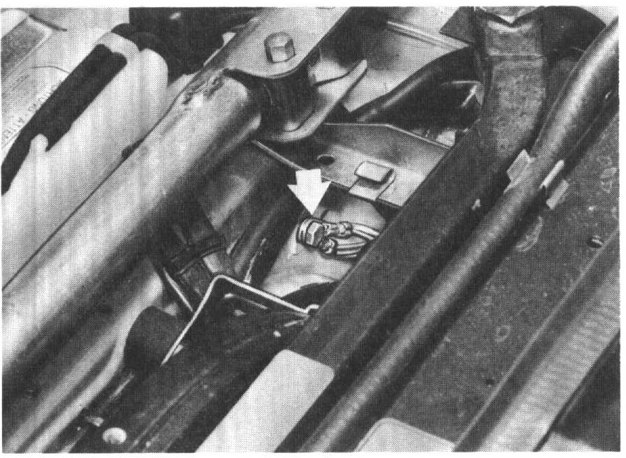
On the opposite side they are in almost a mirrored position, displaced slightly by the ABS unit that was mysteriously missing in your '79.
Hope this helps!
The ground points on my later car are 6mm dia/10mm hex head capscrews with a spider of brown wires with ring tongue connections on them. The "crossmember" description is poor-- they are in the corner where the top of the radiator sheet joins the body at the fender.
On the right side (passenger side on US cars) mine is easy to spot slightly above and forward of the jumpstart terminal, and next to the 14-pin sandwich connector that attaches to the car just ahead/forward of the jumpstart terminal block.
On the opposite side they are in almost a mirrored position, displaced slightly by the ABS unit that was mysteriously missing in your '79.
Hope this helps!
04-02-2002, 10:35 PM
#4
Burning Brakes

Join Date: Jul 2001
Posts: 1,051
Likes: 0
Received 0 Likes
on
0 Posts
2 coil or engine ground cables. (Right side cable goes from coil bracket bolt to topmost front timing belt cover bolt. Left side connects at bottom rear of back timing belt cover.) Check engine ground wire about a foot forward of firewall, and a foot deep on right hand fender well.  <img src="graemlins/icon107.gif" border="0" alt="[icon107]" />
<img src="graemlins/icon107.gif" border="0" alt="[icon107]" />
04-02-2002, 11:48 PM
#6
Three Wheelin'
OK, I've got to ask.
"coil ground cables"
These cables don't act as a ground source for the coils do they? By attaching to the coil brackets and to the engine, they are really just body-to-engine ground cables right? The brackets are not grounded to the coils.
The manual shows the coil terminal 1 (-) connecting to the ignition control unit pin 16.
Just trying to clarify.
Greg
Trending Topics
04-03-2002, 01:26 PM
#8
Burning Brakes
Join Date: Jul 2001
Posts: 1,051
Likes: 0
Received 0 Likes
on
0 Posts
Hi Greg,
That is an excellent observation. Those cables act as grounds for the engine. The coil is grounded through the bracket too, isn't it? It looks like a metal: coil casing, to bracket, to cable, to bolt, to fender wall ground on the coil too. I cannot find a name for those cables in my parts... catalog. You are right. Perhaps with the PET CD, someone can find a name for those engine ground cables.
<img src="confused.gif" border="0">
04-03-2002, 02:00 PM
#9
Three Wheelin'
Thom,
I don't think the coil casing or bracket is meant to provide ground to the coil innerds (technical word!).
The coil casing may be metal (I'd have to check) but it appears to be painted. Body ground may get through the bracket to the coil case, bit I doubt it gets inside the coil.
BTW, I metered the - terminal on the coil to the a known good ground source and I got a higher resistance than 0. That's when I referred to the manual and found that the terminal is fed from the ingnition control unit. I need to research this and find out if this reading should be straight ground, or if the ICU somehow buffers or pads the ground potential to the - terminal of the coil.
Anybody know?
Greg
04-03-2002, 02:26 PM
#10
Chronic Tool Dropper
Lifetime Rennlist
Member
Lifetime Rennlist
Member
Speculating:
The ignition control unit feeds a signal to a pair of switching transistors on the front apron. On my '89 they don't look too exotic. No matter. If the final switching element is a silicon junction, the forward breakdown voltage is somewhere in the 0.7 volt neighborhood. The coil receives +12 volts (give or take) continuously on one side, and the ignition mudule uses the transistors to pull the other side of the coil almost to ground. The "almost" is the breakdown voltage in that last stage.
If you are using a meter that depends on a DC voltage drop to determine resistance, you will get different readings with the meter leads reversed. If you are using a meter that uses an AC signal (some Fluke models for instance) then the reading will not change. If your meter has a diode test function you should be able to see the actual voltage drop in volts across that last junction.
 04-03-2002, 04:33 PM
#12
Addict
Lifetime Rennlist
Member
Lifetime Rennlist
Member
That's great James - much thanks!
Your 'left' and 'right' appear to be referenced looking at the front of the car (makes sense to me in this instance).
Typically, the 'right' side describes the passenger side and the 'left' side describes the driver's side (on lefthand drive vehicles). Right and left referred to from the perspective of sitting in the driver's seat.