

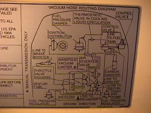
vacuum diagram
 12-06-2002 | 09:54 PM
#1
Thread Starter
Race Car
Joined: Jun 2002
Posts: 4,269
Likes: 25
From: Alabama
Hey guys, where can I find a list of all the vacuum lines on my 928? I still have problems with my vacuum lines.
The car starts up easily (bypass fuelpump relay) but it idles at 1500 RPM then drops to 900 RPM and so on. Last weekend I hooked up the airbox and now it does not hold idle, it shots down. When I give some gas the car idles good. Let it go and it dies.
Or anyone that knows the vacuum lines that connects to the trottle body? Are they 7 or 9 in total?
Thanks
 12-06-2002 | 11:12 PM
#3
Thread Starter
Race Car
Joined: Jun 2002
Posts: 4,269
Likes: 25
From: Alabama
Thanks James, I do not understand the diagram under the hood.
The throttle body of my 928 has two valves but on the diagram it looks like there are 7. How do I interpret that? I know I sound stupid but I am not good with diagrams.
Thanks
The throttle body of my 928 has two valves but on the diagram it looks like there are 7. How do I interpret that? I know I sound stupid but I am not good with diagrams.
Thanks
12-06-2002 | 11:46 PM
#4
Rennlist Member
Joined: Aug 2001
Posts: 502
Likes: 0
It's cool; the throttle body will only have two stems. There are a series of three-way fittings that split the vacuum multiple times; you'll see them on the right-hand side of the throttle body in the diagram.
That's the business end of things. From those two fittings, the lines are split to both fuel pressure regulators (in the back), the pressure damper (in the front) the vacuum advance on the distributor, the vacuum limiter (if your car is a manual), the air-injection control valves I and II, one of which is fed through the screw-in temperature fitting on the passenger's side rear of the "v" between the heads. Looks like a little ailen head w/two antennae
That's 7, by my count. My count has been known to be wrong.
Are you sure this is a vacuum problem? Have you disconnected the current vacuum lines? Why do you need to bypass the fuel pump relay?
12-07-2002 | 01:21 AM
#5
Thread Starter
Race Car
Joined: Jun 2002
Posts: 4,269
Likes: 25
From: Alabama
So from the 7 lines it is not important to which one of the 2 stems they go on to?
Where are the 2 stems (on the throttle body) on the diagram? I see 6 lines going onto the throttle body.
I got new fuel pump relay but it does not work. I want to fix the vacuum lines first, test drive the car and then check the relay.
I got it as a project car, so far I fixed fuel pump/relay, brain/relay, complete tune up kit, rebuild injectors, strainer, sparkplug wires etc, lol.
12-07-2002 | 04:49 AM
#6
Rennlist Member
Joined: Aug 2001
Posts: 502
Likes: 0
I always heard that 928s make tough project cars; damn, this is hard work  . Ok, the posted diagram kinda sucks, on second look.
On the top of the intake plenum (what Porsche calls the "air distributor") is the vacuum source for the auto transmission. (manual, p. 26-3)
On the left side, the venturi tube attaches to the front of the plenum, down low, large hose. That's the upper left connection on the diagram. The second-from-the-bottom left connection on the diagram is where the venturi enters the intake plenum (y'd to brake booster) at the top.
On the front of the throttle body, near the idle adjust screw, is the port for the ignition vacuum advance. (Manual, p. 24) There are actually two ports there; it is my understanding that the second should be covered with a red cap unless your car was manufactured to California spec (I heard this once, I don't know for sure but mine's capped).
On the back of the throttle body, the driver's-side port goes to the decel valve (vacuum limiter, on right side of TB), the pressure regulators and the pressure damper. (Manual p. 24-14 again).
Back of the TB, passenger's side, is the port for the vacuum check valve for the carbon canister (you guessed it, same pages) and to the distributor vacuum retard, if so equipped.
There are additional vacuum connetions to be made from the above lines for the control for the air injection regulation, which I have lost familiarity with since they went away. Sorry.
Excluding the emissions equipment and presuming the venturi system is attached and all other intake ports capped, if you make the connections to the fuel system components and the vacuum advance you should be able to run it for troubleshooting.
Check all connections from the brake booster also, to the HVAC and cruise control.
Try these, also...
<a href="http://ourworld.compuserve.com/homepages/nichols/tip445.htm" target="_blank">Nichol's tip</a>; and
<a href="http://members.rennlist.com/pirtle/svc_intake.html" target="_blank">John Pirtle's page</a>, although it's a different MY.
Anyone else?
. Ok, the posted diagram kinda sucks, on second look. On the top of the intake plenum (what Porsche calls the "air distributor") is the vacuum source for the auto transmission. (manual, p. 26-3)
On the left side, the venturi tube attaches to the front of the plenum, down low, large hose. That's the upper left connection on the diagram. The second-from-the-bottom left connection on the diagram is where the venturi enters the intake plenum (y'd to brake booster) at the top.
On the front of the throttle body, near the idle adjust screw, is the port for the ignition vacuum advance. (Manual, p. 24) There are actually two ports there; it is my understanding that the second should be covered with a red cap unless your car was manufactured to California spec (I heard this once, I don't know for sure but mine's capped).
On the back of the throttle body, the driver's-side port goes to the decel valve (vacuum limiter, on right side of TB), the pressure regulators and the pressure damper. (Manual p. 24-14 again).
Back of the TB, passenger's side, is the port for the vacuum check valve for the carbon canister (you guessed it, same pages) and to the distributor vacuum retard, if so equipped.
There are additional vacuum connetions to be made from the above lines for the control for the air injection regulation, which I have lost familiarity with since they went away.
Sorry.Excluding the emissions equipment and presuming the venturi system is attached and all other intake ports capped, if you make the connections to the fuel system components and the vacuum advance you should be able to run it for troubleshooting.
Check all connections from the brake booster also, to the HVAC and cruise control.
Try these, also...
<a href="http://ourworld.compuserve.com/homepages/nichols/tip445.htm" target="_blank">Nichol's tip</a>; and
<a href="http://members.rennlist.com/pirtle/svc_intake.html" target="_blank">John Pirtle's page</a>, although it's a different MY.
Anyone else?
Trending Topics
12-08-2002 | 10:55 PM
#8
Thread Starter
Race Car
Joined: Jun 2002
Posts: 4,269
Likes: 25
From: Alabama
Thanks James, I hooked up all the vacuum lines today. I found V1-A P24-208 in the manual to be very helpful too. It says fuel path for 1985 but its more easy to understand and seems more like a diagram for 1984.
The car idles high but the idle is very steady. Next weekend I will set the idles and take it for a test drive. I hope the transmission is fine.
The car idles high but the idle is very steady. Next weekend I will set the idles and take it for a test drive. I hope the transmission is fine.
12-14-2002 | 11:12 AM
#10

Rennlist Member
Joined: Dec 2002
Posts: 1,975
Likes: 0
From: Southern New England
While we're on the topic...
Would anyone be able to tell me where the vacuum line from the air pump diverter valve goes? I just noticed mine dangling in the vee of the engine & the manual isn't really very clear about it. I have a hunch that it might go under the throttle body somewhere, but good luck getting it back on if that's the case!
I scoured the web for info on this & have the CD and print versions of the service manuals, but info on this is scarce. The best I came up with is that it tied into the throttle body somewhere... I'm hoping that someone will tell me, "oh, just pull the flow sensor off and you will be able to reach it", or something like that. :-)
12-16-2002 | 12:08 AM
#12
Rennlist Member
Joined: Dec 2002
Posts: 1,975
Likes: 0
From: Southern New England
Thanks for the welcome, Randy. <img src="graemlins/xyxwave.gif" border="0" alt="[bigbye]" /> The subject would be my recently acquired 89...
Busy day with that. Removing the mass flow sensor & rubber boot was the way to do it. Had to flush the connection with brake cleaner - it was plugged with crud from being open to air. The only reason I can think of why the hose was off is that someone forgot to put it back on when they were wrapping up a job (and this car has had those kinds of jobs). Also, they had them reversed at the actuators (white hose was on the canister valve instead of air pump valve). Maybe it won't make a bit of difference on how it runs, but at least I know it's right now.
Busy day with that. Removing the mass flow sensor & rubber boot was the way to do it. Had to flush the connection with brake cleaner - it was plugged with crud from being open to air. The only reason I can think of why the hose was off is that someone forgot to put it back on when they were wrapping up a job (and this car has had those kinds of jobs). Also, they had them reversed at the actuators (white hose was on the canister valve instead of air pump valve). Maybe it won't make a bit of difference on how it runs, but at least I know it's right now.
08-25-2009 | 11:57 PM
#13
Advanced
Joined: Aug 2009
Posts: 99
Likes: 0
From: Nashville, TN
If you look from the driver side (with air box off) to the back of the TB passenger rear of TB, almost down in the valley, there are 2 nipples setting together, what do they hookup to? To get to them you need to take the air regulator and air box off the car and I am really don't want to run the car with the box off so I can't tell if these nipples are giving vacuum or requiring vacuum to be given to them
08-26-2009 | 12:03 AM
#15
Rennlist Member
Joined: Sep 2007
Posts: 12,155
Likes: 370
From: Johnson City, TN
Can you post the picture of what you are talking about? I don't see the ones you are talking about on the 84 I'm looking at in the basement with the airbox off. Should be same as 83.