
igntion wiring & alarm bypass
 06-01-2002, 12:31 PM
#1
Addict
Lifetime Rennlist
Member
Lifetime Rennlist
Member
Thread Starter
1987 s4, NO FACTORY ALARM INSTALLED.
Im adding a keyless entry module that also has remote start capability. I have a few questions on the wires lead fromt the IGNITION in the dash.
somewhat summed up here...
<a href="http://members.rennlist.com/v1uhoh/ignition.htm" target="_blank">http://members.rennlist.com/v1uhoh/ignition.htm</a>
also on that link i have a question about the location of the factory alarm, if it were to be installed. In my digging i found a couple of wires that were jumpered that i believe were used in conjunction with the alarm. I think these wires were used to disable the EZK or some portion of the LH thus immobilizing the car when the alarm was triggered. IF these are the wires i would like to wire in my own "seceret immobilzer button" : )
thanks
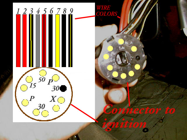
this is one of the pictures you will see on the link above...
Im adding a keyless entry module that also has remote start capability. I have a few questions on the wires lead fromt the IGNITION in the dash.
somewhat summed up here...
<a href="http://members.rennlist.com/v1uhoh/ignition.htm" target="_blank">http://members.rennlist.com/v1uhoh/ignition.htm</a>
also on that link i have a question about the location of the factory alarm, if it were to be installed. In my digging i found a couple of wires that were jumpered that i believe were used in conjunction with the alarm. I think these wires were used to disable the EZK or some portion of the LH thus immobilizing the car when the alarm was triggered. IF these are the wires i would like to wire in my own "seceret immobilzer button" : )
thanks
this is one of the pictures you will see on the link above...
 06-01-2002, 06:27 PM
#2
Addict
Rennlist Member
Rennlist Member
Join Date: May 2001
Location: Seattle - it's not Hell, but you can see it from here!
Posts: 3,679
Likes: 0
Received 2 Likes
on
2 Posts
this appears to be the alarm connector. let's give this a try:
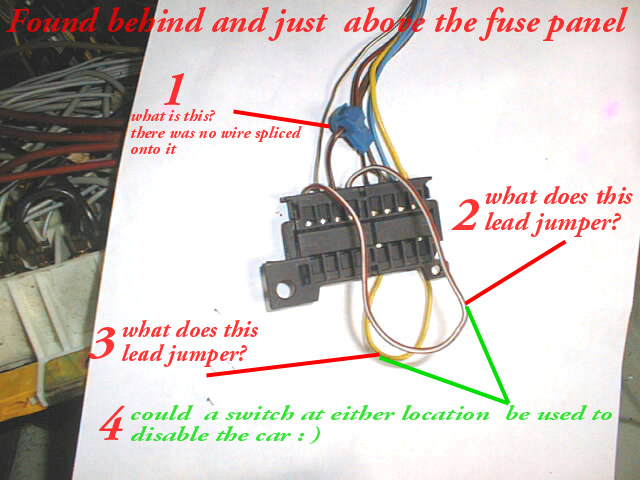
from right to left:
Pin 1 (yellow): goes to pin 86 on the EZK relay (XVI)
Pin 2 (blue): goes to pin 15 on the ABS control module
Pin 3 (brown): goes to ground point V (by relay panel)
Pin 4 (black/red): goes to 12v (key on)
Pin 5 (red/white): jumer to pin 8. this is your item #2
Pin 6 (red/black): goes to pin 30 on the EZK (XVI) and ABS (XVII) relays and fuse 16 (ABS)
Pin 7 (brown/white): interior light trigger
Pin 8 (red/white): jumper to pin 5
1 looks like it was just a voltage tap, it's not on the wire diagram. wouldn't worry about it or mess with it.
2 is for the horn. it goes nowhere, cutting it will do nothing.
3 looks like it jumpers pin 1 and 4. if it does, it looks like cutting it should disable power to the EZK.
now if you cut it and the car doesn't start, then you reconnect it and the car still doesn't start, don't blame me for frying your EZK. looks like it should work though...
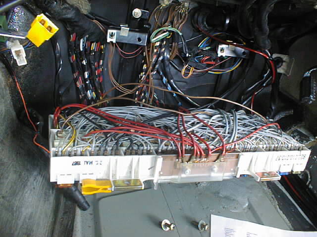
hmm, looks like one of the racks in a 767...

d
from right to left:
Pin 1 (yellow): goes to pin 86 on the EZK relay (XVI)
Pin 2 (blue): goes to pin 15 on the ABS control module
Pin 3 (brown): goes to ground point V (by relay panel)
Pin 4 (black/red): goes to 12v (key on)
Pin 5 (red/white): jumer to pin 8. this is your item #2
Pin 6 (red/black): goes to pin 30 on the EZK (XVI) and ABS (XVII) relays and fuse 16 (ABS)
Pin 7 (brown/white): interior light trigger
Pin 8 (red/white): jumper to pin 5
1 looks like it was just a voltage tap, it's not on the wire diagram. wouldn't worry about it or mess with it.
2 is for the horn. it goes nowhere, cutting it will do nothing.
3 looks like it jumpers pin 1 and 4. if it does, it looks like cutting it should disable power to the EZK.
now if you cut it and the car doesn't start, then you reconnect it and the car still doesn't start, don't blame me for frying your EZK. looks like it should work though...
hmm, looks like one of the racks in a 767...
d
06-01-2002, 07:18 PM
#3
Addict
Lifetime Rennlist
Member
Lifetime Rennlist
Member
Thread Starter
LOL thanks dave!! I just got access to the shop manuals and the electrical section so im going over some of it now..below is an update
It is similar to 767 but suprisingly MINUS about 5 lbs of LINT and airborne STUFF!!
<a href="http://members.rennlist.com/v1uhoh/ignition.htm" target="_blank">http://members.rennlist.com/v1uhoh/ignition.htm</a>
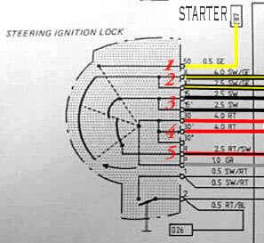
Quoted Per instructions I need to find the wires to.....suming the dooted line on the schematic is KEY POSTION?
A) "Starter wire at igntion switch, which has power present ONLY when in the starting postion" THIS I KNOW IS THE YELLOW wire, aka the starter
B) "accessory circuit wire at the igntion switch, which has power ONLY in the RUN posrion" MY guess here is #2, the BLACK/YELLOW wires.
C) " ignition circuit wire at the igntion switch, which has power present ONLY in the RUN and STARTING POSTIONS. This wire supplies power to the vehicle igntion system" MY guess i 3 which is THE BLACK set of wires
It is similar to 767 but suprisingly MINUS about 5 lbs of LINT and airborne STUFF!!
<a href="http://members.rennlist.com/v1uhoh/ignition.htm" target="_blank">http://members.rennlist.com/v1uhoh/ignition.htm</a>
Quoted Per instructions I need to find the wires to.....suming the dooted line on the schematic is KEY POSTION?
A) "Starter wire at igntion switch, which has power present ONLY when in the starting postion" THIS I KNOW IS THE YELLOW wire, aka the starter
B) "accessory circuit wire at the igntion switch, which has power ONLY in the RUN posrion" MY guess here is #2, the BLACK/YELLOW wires.
C) " ignition circuit wire at the igntion switch, which has power present ONLY in the RUN and STARTING POSTIONS. This wire supplies power to the vehicle igntion system" MY guess i 3 which is THE BLACK set of wires