When you click on links to various merchants on this site and make a purchase, this can result in this site earning a commission. Affiliate programs and affiliations include, but are not limited to, the eBay Partner Network.
Anyone have any thoughts on why my headlight motor will lower but not raise the headlights?
The actual head lights do not turn on either.
But if i turn/dial the head lights to their raised position and then press the headlight switch/button the head lights will lower (but not raise).
-relay replaced
-ignition switch replaced
-grounds checked, cleaned, deoxited
-motor removed and brushed/cleaned
-every iteration of 1,2,3,4 connectors tried.
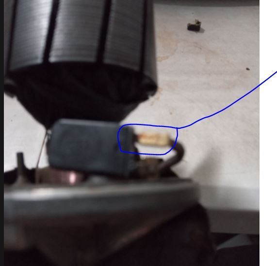
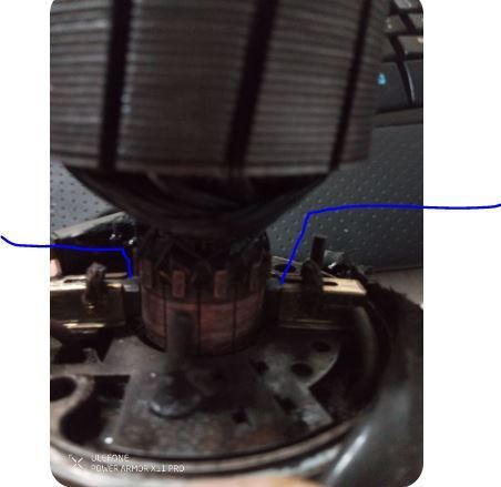
One out of the box thought was on a youtube video that mentions the two contact points(blue) arrows need to be touching.
One of his contact points was loose so he broke off the plastic housing and JB welded it back together.
But he doesn't go on to say if both contact points not touching was his issue for the malfunction headlights.
(not actual photograph - for illustrative purposes only)
Observations:
1. Pin 1 is powered (+12V) only when the light switch is in position 2 (headlights on)
2. Pin 2 is powered only when the light switch is in position 0
3. Pin 3 is powered when 12V is applied to the metal disc in the motor by either Pin 1 or Pin 2
4. Lighting relay unit applies power to Pin 4 only while Pin 3 is powered
5. Pin 4 spins the headlight motor when power is applied to it
Deduced motor operation - raising headlights:
1. Pin 1 is powered by switching headlights on
2. Provided motor disc is in the 'headlights lowered' position, power from Pin 1 is transferred to Pin 3
3. Pin 3 feeds back to lighting relay which applies power to Pin 4
4. Pin 4 spins motor
5. Headlights rise until motor disc rotation reaches the spot where connection between Pin 1 and Pin 3 is broken
Deduced motor operation - lowering headlights:
1. Pin 2 is powered if light switch is off (position 0)
2. Provided motor disc is in the 'headlights raised' position, power from Pin 2 is transferred to Pin 3
3. Pin 3 feeds back to lighting relay which applies power to Pin 4
4. Pin 4 spins motor
5. Headlights lower until motor disc rotation reaches the spot where connection between Pin 2 and Pin 3 is broken
Testing headlight motor out of the car:
- Connect negative side of a battery to a good earth point on the motor casing
- Run a small jumper wire between Pin 3 and Pin 4
- To test raising headlights, apply 12V from the battery to Pin 1 (if motor is in 'headlights lowered' position it should spin half a turn then stop)
- To test lowering headlights, apply 12V from the battery to Pin 2 (if motor is in 'headlights raised' position it should spin half a turn then stop)
- To test if motor will spin at all, apply 12V directly to pin 4
This is by no means a complete analysis, I'm still trying to work out exactly what goes on inside the lighting combo relay amongst other things.
The representation of this combo relay unit in the wiring diagram is oversimplified at best and incorrect at worst.
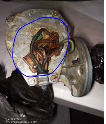
As the problem with my car seems to be in that relay, I've pulled it out and taken the cover off and attempting to map the actual circuit paths inside.
If anybody has already done this task and could share a diagram it would be much appreciated.
Anyone have any thoughts on why my headlight motor will lower but not raise the headlights?
The actual head lights do not turn on either.
Just a thought on this: if the headlights don't come on then you have other problems.
By my reading of the wiring diagram they are independent of the motor operation.
However, if there is no power to the headlights you most likely won't have power to the motor on the pin needed to raise them.
So maybe best to get the headlights not coming on issue sorted first.
If the headlights aren't in the fully raised position they won't come on so there is a direct relationship. You could however wind the motor to the fully-up position and test headlight operation then (so you probably need to remove the Red/Black Motor Wire to avoid the motor driving back down - assuming wires are in the correct positions).
The interlock here is not from the motor driving relay(s) themselves (1 for early system, 2 for S4+) but from the wiper track position switches that control the motor relay(s).
Observations:
1. Pin 1 is powered (+12V) only when the light switch is in position 2 (headlights on)
2. Pin 2 is powered only when the light switch is in position 0
3. Pin 3 is powered when 12V is applied to the metal disc in the motor by either Pin 1 or Pin 2
4. Lighting relay unit applies power to Pin 4 only while Pin 3 is powered
5. Pin 4 spins the headlight motor when power is applied to it
Deduced motor operation - raising headlights:
1. Pin 1 is powered by switching headlights on
2. Provided motor disc is in the 'headlights lowered' position, power from Pin 1 is transferred to Pin 3
3. Pin 3 feeds back to lighting relay which applies power to Pin 4
4. Pin 4 spins motor
5. Headlights rise until motor disc rotation reaches the spot where connection between Pin 1 and Pin 3 is broken
Deduced motor operation - lowering headlights:
1. Pin 2 is powered if light switch is off (position 0)
2. Provided motor disc is in the 'headlights raised' position, power from Pin 2 is transferred to Pin 3
3. Pin 3 feeds back to lighting relay which applies power to Pin 4
4. Pin 4 spins motor
5. Headlights lower until motor disc rotation reaches the spot where connection between Pin 2 and Pin 3 is broken
Testing headlight motor out of the car:
- Connect negative side of a battery to a good earth point on the motor casing
- Run a small jumper wire between Pin 3 and Pin 4
- To test raising headlights, apply 12V from the battery to Pin 1 (if motor is in 'headlights lowered' position it should spin half a turn then stop)
- To test lowering headlights, apply 12V from the battery to Pin 2 (if motor is in 'headlights raised' position it should spin half a turn then stop)
- To test if motor will spin at all, apply 12V directly to pin 4
This is by no means a complete analysis, I'm still trying to work out exactly what goes on inside the lighting combo relay amongst other things.
The representation of this combo relay unit in the wiring diagram is oversimplified at best and incorrect at worst.
As the problem with my car seems to be in that relay, I've pulled it out and taken the cover off and attempting to map the actual circuit paths inside.
If anybody has already done this task and could share a diagram it would be much appreciated.
Thanks for your comments - we're getting closer to resolving this issue for 928 owners.
My question is how to I test the motor outside on my work bench? Is there a way I can do it with a 9v battery? Or what sort of power source and wires do i need?
I believe power is reaching the motor as I can manually dial up the motor, then when i turn on the switch the motor will activate and lower the headlights.
Also, i tried every iteration but I left the wires based on the cut and paste image of the WSM
pin 1 - brown red
pin 2- white black
pin 3 - yellow green
pin 4 - red black
What is interesting is when I pull and disconnect the brown/red wire from pin 1 and touch the brown/red wire to the white/black wire while the white/black wire is plugged into pin 2, the head lights go on.
Also i've checked and cleaned the below.
There's a youtube video where the guy points out one of his tabs was not touching/skimming properly.
My question is how to I test the motor outside on my work bench? Is there a way I can do it with a 9v battery? Or what sort of power source and wires do i need?
As per my PM to you, you'd need a smallish capacity (5Ah would do) 12V battery and some medium gauge testing wires, ideally with alligator clips at each end.
Originally Posted by 928Collector
i tried every iteration but I left the wires based on the cut and paste image of the WSM
pin 1 - brown red
pin 2- white black
pin 3 - yellow green
pin 4 - red black
Thinking about it more now, it may not matter which of white/black and brown/red is connected to pin 1 and which is connected to pin 2.
As long as you have the condition where only one of those two wires is powered in any given situation, the motor doesn't care which is which.
Originally Posted by 928Collector
What is interesting is when I pull and disconnect the brown/red wire from pin 1 and touch the brown/red wire to the white/black wire while the white/black wire is plugged into pin 2, the head lights go on.
Sounds like you are not getting power in your white/black wire, which also runs to the headlights.
Assuming you have power in your brown/red wire, by touching it to the white/black wire you are powering your headlights.
...Thinking about it more now, it may not matter which of white/black and brown/red is connected to pin 1 and which is connected to pin 2.
As long as you have the condition where only one of those two wires is powered in any given situation, the motor doesn't care which is which....
The motor is not connected here - it is controlled only via the relay. There are diodes in series with terminal 56 & 30b where the anode goes to these terminals and the cathodes both go to 86 via the rotating track. So the White/Black wire and the Brown/Red wire must be more positive in the circuit than the Green/Yellow wire or no current will flow. The relay certainly cares which is which - if they are wrong the motor will drive up for off and down for HL on. Be aware - it is possible for the track wipers to not connect for any of these 3 track connections (check physical connection) OR for either of the diodes to be blown. You can test these directly at the pins (depending on the motor rotation). The connection to the motor MUST be correct - any misplaced wires will certainly lead to inoperability.
If the headlights aren't in the fully raised position they won't come on so there is a direct relationship.
The interlock here is not from the motor driving relay(s) themselves (1 for early system, 2 for S4+) but from the wiper track position switches that control the motor relay(s).
OK, I'm interested in how the mechanism to prevent the headlights coming on unless they are fully raised works.
In the context of the S2 system, power from the motor disc due to engagement with either pin 1 or pin 2 on the connector is transferred to pin 3 which is connected to the green/yellow wire.
This wire runs back to terminal 86M on the headlight relay which closes a switch to connect 30M to 30a.
30M is the red/black wire which powers the motor, which leads me to believe 30a must be powered at all times so the headlights can be raised or lowered as needed.
The headlights themselves are powered from terminals 56a and 56b on the relay which are somehow controlled by the 'mystery section' of the relay unit which has terminals 56, X and 30b as inputs and 30bM as an output.
- 56 is the white/black wire which runs to the headlight motor and positon 2 on the light switch
- 30b also runs back to the light switch
- X I have no idea what it does, maybe a general auxiliary supply of +12V?
- 30bM is the brown/red wire that runs to the headlight motor
How does the 'mystery section' of the relay unit know when the headlights are fully raised so that it's OK to apply power to 56a and/or 56b to light the headlights?
The motor is not connected here - it is controlled only via the relay.
True, but it's worth noting the white/black wire running to the motor will have power applied when the light switch is in position 2 independent of relay operation.
Originally Posted by Alan
The relay certainly cares which is which - if they are wrong the motor will drive up for off and down for HL on.
But in the S2 system the motor only rotates in one direction, so headlight transition from down to up is the same motor movement as for up to down.
So as long as you have the headlights physically in their correct position, should it not then matter for the S2 which is which?
Not trying to be difficult, but as I have a relay unit that I'm not sure is working 100% correctly I can't verify for myself.
OK, I'm interested in how the mechanism to prevent the headlights coming on unless they are fully raised works.
In the context of the S2 system, power from the motor disc due to engagement with either pin 1 or pin 2 on the connector is transferred to pin 3 which is connected to the green/yellow wire.
This wire runs back to terminal 86M on the headlight relay which closes a switch to connect 30M to 30a.
30M is the red/black wire which powers the motor, which leads me to believe 30a must be powered at all times so the headlights can be raised or lowered as needed.
The headlights themselves are powered from terminals 56a and 56b on the relay which are somehow controlled by the 'mystery section' of the relay unit which has terminals 56, X and 30b as inputs and 30bM as an output.
- 56 is the white/black wire which runs to the headlight motor and positon 2 on the light switch
- 30b also runs back to the light switch
- X I have no idea what it does, maybe a general auxiliary supply of +12V?
- 30bM is the brown/red wire that runs to the headlight motor
How does the 'mystery section' of the relay unit know when the headlights are fully raised so that it's OK to apply power to 56a and/or 56b to light the headlights?
Cheers,
Brian
Direct from the position switches that also go to the relay - The HL on/off relay is controlled by the headlights fully up position switch. This is true for all years.
X is powered only with accessory or ignition on and but not with starter engaged.
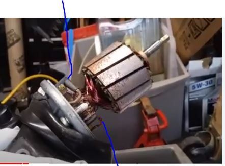
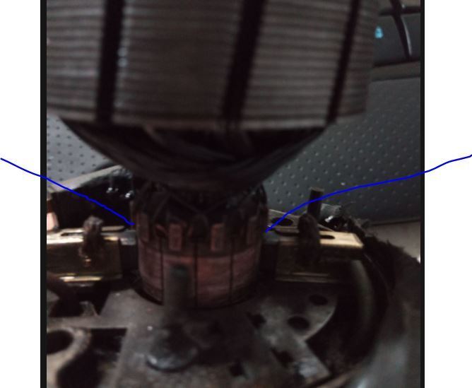
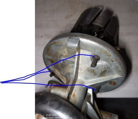
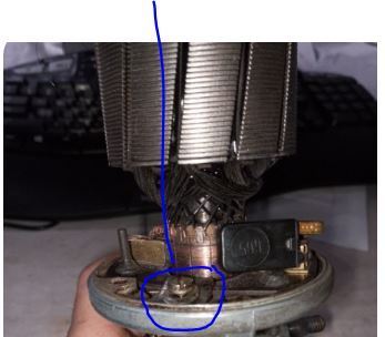
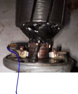
I pulled apart the motor and cleaned several connections. gently push these three(3) plugs up from the bottom and pull from the top these two(2) contact points must be touching while the spindle is free spinning making a slight clicking noise upon each turn removing this screw and its elongated stay nut will allow you to pull out the entire mechanism. There was decades of gunk underneath. I cleaned / deoxit and checked for any loose connections. Be sure not to pull this wire out/off its connections - it has enough slack to pull the mechanism up and out.
Last edited by 928Collector; 06-30-2024 at 11:31 PM.


 06-17-2024, 04:00 PM