

Roll on to 140mph with a Twinscrew"Supermodel"
 02-11-2005, 01:34 PM
#31
Intermediate

Join Date: Oct 2004
Posts: 29
Likes: 0
Received 0 Likes
on
0 Posts
Hi,
Nice Chart B951S,
The chart implies that the load resistor in the GM ECU is 5 kOhm (calculated from GM voltage table and Factory calibration resistance data in the chart) You can make the load resistor by putting 2 10kOhm in parallel. Then you can directly enter the posted voltages from the GM table on the left in a LogWorks lockup table.
If you use the 8 voltages in the table with the AEM raw Volts, the load resistor is 2.2 kOhm.
Regards,
Klaus
Regards,
Klaus
 02-11-2005, 03:34 PM
#32
Three Wheelin'
RE: injectors not being run at more than 80% of the duty cycle--I thought the whole thing with the LH or the EZK is that when it senses WOT it goes to open loop and leaves the injectors on constantly.
These systems were designed to run the injectors 100% during WOT, and 19# injectors were chosen and mapped such that the AF mixture would be "optimized" (using this term loosely, since open loop is really the opposite of optimized, since o2 sensor measurements are no longer being considered) at WOT.
I assumed that 944s did the same thing; I am surprised to hear that everyone else is so surprised about how the SCd 928s manage air/fuel at WOT, since we're just doing what the factory did, but with bigger injectors and fuel pressure as the changing variable rather than reprogramming the fuel maps to compensate for more air. It seems to be an easy and elegant solution that is no less precise than what the factory did, without resulting to what I would assume to be expensive and complicated alternatives, like entirely new management systems or remapped chips.
If it's bad to run the injectors at more than 80% duty cycle, why were these cars designed by the factory to go to 100% at WOT, and wouldn't we expect to have heard of problems along the way? It doesn't make sense.
02-11-2005, 06:01 PM
#33
Intermediate
Join Date: Oct 2004
Posts: 29
Likes: 0
Received 0 Likes
on
0 Posts
Hi,
I doubt very much that Bosch or Porsche designed these things to run at 100%. That is asking for trouble because there's no way anymore that AFR can be maintained.
WOT does NOT mean 100% duty cycle. Open loop just means that the ECU does not fine-regulate AFR using the O2 sensor. Instead it uses the pre-stored maps and the MAF sensor to control injector timing. It just so happens that if the MAF is pegged at 5V, the duty cycle goes to 100% because that's what the ECU is programmed to do. But in a stock application the MAF does not peg.
You can see that also in the log. As long as RPMs stay lower, the MAF sensor is not pegged and duty cycle is not at 100% even though he's at WOT.
At 100% duty cycle the fuel flow is constant and there's no way at all the ECU can maintain adequate fuel flow. Of course you can 'optimize' the injector size for one operating point as an 'elegant' solution, but then it runs too lean or too rich outside of that one point. A 'point' being one RPM, manifold pressure and intake temperature point. Varying the pressure by SC, turbo or altitude puts more or less air into the engine and it requires more (or less) fuel. Running at 100% DC is kind of like locking your steering wheel while driving on a straight road. As long as it is straight and no wind, you survive. But then it bends and your dead.
Regards,
Klaus
02-11-2005, 06:39 PM
#35
Addict
Lifetime Rennlist
Member
Lifetime Rennlist
Member
Thread Starter
Originally Posted by Lagavulin
Klaus, thank you for 'stopping in'! 
So..with this data from the previous posting of the GM sensor data, you need to place 2 10K ohm resistors in paralell in the temp circuit that will be used by logworks.
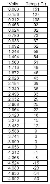
I think i do have something "a muck" in the temp readings as i look at the graph. The data is pretty linear between 140f (60C) and 14f(-10c). This would explain why my GM sensore is dead on with my TC readings �at 60 F for example.
Ive seen the performace chart for my SC and my discharge temps should be higher than I am seeing. They are in the area of the graph were things don�t increase in a linear fashion.
As ive said ive got the LM-1/3 all working...just have to tweek it here and there.
Whats the latest on the XD-1 disply Klaus?
 02-11-2005, 06:43 PM
#36
Rennlist Member
Originally Posted by klatinn
Hi,
I doubt very much that Bosch or Porsche designed these things to run at 100%. That is asking for trouble because there's no way anymore that AFR can be maintained.
WOT does NOT mean 100% duty cycle. Open loop just means that the ECU does not fine-regulate AFR using the O2 sensor. Instead it uses the pre-stored maps and the MAF sensor to control injector timing. It just so happens that if the MAF is pegged at 5V, the duty cycle goes to 100% because that's what the ECU is programmed to do. But in a stock application the MAF does not peg.
You can see that also in the log. As long as RPMs stay lower, the MAF sensor is not pegged and duty cycle is not at 100% even though he's at WOT.
At 100% duty cycle the fuel flow is constant and there's no way at all the ECU can maintain adequate fuel flow. Of course you can 'optimize' the injector size for one operating point as an 'elegant' solution, but then it runs too lean or too rich outside of that one point. A 'point' being one RPM, manifold pressure and intake temperature point. Varying the pressure by SC, turbo or altitude puts more or less air into the engine and it requires more (or less) fuel. Running at 100% DC is kind of like locking your steering wheel while driving on a straight road. As long as it is straight and no wind, you survive. But then it bends and your dead.
Regards,
Klaus
I doubt very much that Bosch or Porsche designed these things to run at 100%. That is asking for trouble because there's no way anymore that AFR can be maintained.
WOT does NOT mean 100% duty cycle. Open loop just means that the ECU does not fine-regulate AFR using the O2 sensor. Instead it uses the pre-stored maps and the MAF sensor to control injector timing. It just so happens that if the MAF is pegged at 5V, the duty cycle goes to 100% because that's what the ECU is programmed to do. But in a stock application the MAF does not peg.
You can see that also in the log. As long as RPMs stay lower, the MAF sensor is not pegged and duty cycle is not at 100% even though he's at WOT.
At 100% duty cycle the fuel flow is constant and there's no way at all the ECU can maintain adequate fuel flow. Of course you can 'optimize' the injector size for one operating point as an 'elegant' solution, but then it runs too lean or too rich outside of that one point. A 'point' being one RPM, manifold pressure and intake temperature point. Varying the pressure by SC, turbo or altitude puts more or less air into the engine and it requires more (or less) fuel. Running at 100% DC is kind of like locking your steering wheel while driving on a straight road. As long as it is straight and no wind, you survive. But then it bends and your dead.
Regards,
Klaus
Any of you guys running WOT for long periods at the track ever had ECU injector driver problems, injector failures or premature pump failure?
02-12-2005, 11:52 AM
#37
Intermediate
Join Date: Oct 2004
Posts: 29
Likes: 0
Received 0 Likes
on
0 Posts
Hi Tony,
Re: XD-1
All tests are completed and production has started. We finally got the last molded parts in (we were not the only ones affected by the floods, our suppliers too). XD-1's should be shipping with the next 2 weeks.
Re: 100% duty cycle with stock ECU
The reason the injectors run at 100% is because the MAF sensor is pegged. It's designed for air-flow for a n/a application. More air flows in, it just can't read it and the ECU goes 100% because that's all it can do. When running bigger injectors on a MAF based ECU you should match the MAF sensor flow capacity to the larger injectors. Because its much easier to get big injectors than matching MAFs, many people don't mess with it, with broken engines as result. Larger injectors have no effect on the injector drivers as long as you keep the same kind (high impedance for high impedance drivers and low imp. for low imp. drivers).
MAF eliminators typically take MAP and IAT and synthesize a MAF signal for the ECU. You wire them in instead of the MAF. Some pass through a 'massaged' MAF signal for low load conditions.
If and when I have the time I'll write some firmware load for the Auxbox to turn it into one. All you have to do is connect the MAF and IAT. MAP sensor is already in the Auxbox. Then you wire one of the lines going 0..5V to the LM-1 to your ECU as MAF signal. That would make it programmable.
Regards,
Klaus
02-12-2005, 01:41 PM
#38
Developer
Excellent thread - and a wonderful post, Tony.
I like the 2-second sampling points, just perfect. It may be helpful to know what the ambient temperature and humidity was that time that day if you know it. It may help you guys sort out some of the "what if" info.
It looks like you are really close to having yours dialed in, Tony. Not much room for improvement any more!
Has anyone said what caused the lean spike at the 9 second spot? You went back to a good air/fuel ratio right away again after that - and held it - so we know it is not a delivery problem. It almost looks like a mistake. Do you figure that it coresponds to bumping the rev limiter about then?
Congratulations!
02-12-2005, 02:11 PM
#39
Addict
Lifetime Rennlist
Member
Lifetime Rennlist
Member
Thread Starter
Thanks Carl. Slowly but surely im messing with it here and there when i have time and good weather. The spike is do to the revlimiter. I was manualy shifting the Auto and of course forgot about 2-3 shift  You can see it was for a very breif moment but none the less it looks dramatic on the data logging. Shows you what a cool little tool this is.! The motor farts i know about it....i just have to learn how to interpret all of the data and stuff and understand what it is showing me. Klaus's post earlier is an example. I could just turn a few adjustments an forget about it but as ive said in the past i like this kind of stuff....logging..data...what makes it tick and why...etc etc. If i could steal a "black box" from the tail of one of the airplanes and rig it up i would!
Thanks for the upadte Klaus. Are orders being taken yet or are you waiting until they are in hand??
ok..off to BOS
You can see it was for a very breif moment but none the less it looks dramatic on the data logging. Shows you what a cool little tool this is.! The motor farts i know about it....i just have to learn how to interpret all of the data and stuff and understand what it is showing me. Klaus's post earlier is an example. I could just turn a few adjustments an forget about it but as ive said in the past i like this kind of stuff....logging..data...what makes it tick and why...etc etc. If i could steal a "black box" from the tail of one of the airplanes and rig it up i would! Thanks for the upadte Klaus. Are orders being taken yet or are you waiting until they are in hand??
ok..off to BOS
02-12-2005, 05:57 PM
#41
Intermediate
Join Date: Oct 2004
Posts: 29
Likes: 0
Received 0 Likes
on
0 Posts
Tony,
We are not taking orders until we can ship right away.
John,
If the ECU goes to 100% DC, the MAF is pegged as far as the ECU is concerned. It would be interresting to log also MAF voltage. Tony can rig one of the Temp channels to the MAF output. This way we can see if it's the MAF or the ECU.
Regards,
Klaus
02-12-2005, 06:39 PM
#42
Rennlist Member
Experimenting with 944 turbos, the MAF's dont usually peg 5v even at crazy boost. Its the map in the DME that will max out the injectors for a given MAF voltage. Thats what you can use a MAF piggback becuase to 'scale down' the map voltage. If it was topped out at 5v, the ECU would basically be 'blind' to air flow data at that point
02-12-2005, 06:46 PM
#43
Banned
Join Date: May 2001
Location: The Great Northwest
Posts: 12,264
Likes: 0
Received 3 Likes
on
3 Posts
In a very well done book on EMS & tuning I am reading it states many times you don't want to run more than 80% DC. The injector can fail or 'missfire' if ran this way for long.
Last edited by Jim_H; 02-12-2005 at 10:29 PM.
02-12-2005, 08:50 PM
#44
Intermediate
Join Date: Oct 2004
Posts: 29
Likes: 0
Received 0 Likes
on
0 Posts
Well,
I've seen MAF sensors that peg out at less than 5V, specially older models. The circuit in the MAF sensor does not neccessarily put out 5V when pegged, it can be a lower value. In any case the ECU 'knows' its MAF sensor and pegs the DC when maximum readable MAF is reached.
I don't know if that's the case in the 928 ECU. The only way to find out is to log MAF and DC over boost/RPM. If the MAF signal 'sticks' at some value while DC is 100%, thats its peg voltage.
Regards,
Klaus
02-12-2005, 10:04 PM
#45
Drifting
Join Date: Feb 2002
Location: Redondo Beach, CA>>>>Atlanta,GA
Posts: 2,015
Likes: 0
Received 0 Likes
on
0 Posts
2. Your boost rises slightly when you shift (RPM jump to lower) and falls with increasing RPM. This could be pressure loss in the intake path (air friction in the pipes/IC).
Thanks for visiting our forum.
As I look at the graph I don't see where the boost falls off at all. However I'll ask Tony to send me the file so I can look at it more closely. And if it did, it wouldn't be due to air friction in the pipes/IC. Boost is measured on this system about 1" from an intake port so there are no pipes, IC, etc to slow air down after boost is measured. This means the rise in pressure is due to an event not having to do with flow such as increased load, which is the case here. The "spike" in pressure is due to the increased engine load after shifting.
Andy K