When you click on links to various merchants on this site and make a purchase, this can result in this site earning a commission. Affiliate programs and affiliations include, but are not limited to, the eBay Partner Network.
The speedo has worked on and off over the last few years I have owned my �79, but not worked at all recently.
I have now done the following in an attempt to solve the problem.
1, Checked the signal in the rear by raising one wheel and using a continuity multimeter - working
2, Had the speedo checked by a local speedo repair firm - working
3, Replaced the old circuit board (it needed it!) with the Lutz Auto - looks great
4, Have checked continuity of the black/blue wire from the dash right plug #12 to the CE
I'm looking for help on what to do next, so any suggestions welcomed
Can someone tell me where the two wires in the boot terminate on the CE board, I have the manual but struggle with reading the electrical side.
The problem is you need a speedo to get a NZ warrant of fitness before driving on the roads - I�m missing my 928 time.
While I'm not an authority on all things 928, I have done a bit of a deep dive into speedometer functionally.
Assuming that you feel comfortable opening the gauge itself, remove the back cover and access the rear of the speedometer.
Test the zener diode and capacitors on the PCB.
My speedometer had a shorted zener diode, and a number of caps were bulging or vented, so I ended up ordering a complete set from digikey and replacing them all.
There is also a recent YouTube video showing speedometer calibration and testing by one of our fellow owners, using an Arduino and a pair of transistors.
My post about repairing the speedo in my car is here.
Last edited by Hey_Allen; Mar 20, 2023 at 01:39 PM.
There is also a recent YouTube video showing speedometer calibration and testing by one of our fellow owners, using an Arduino and a pair of transitions.
Thanks for the replies, I had the unit serviced and calibrated by a specialist instrumentation firm so happy it is working correctly.
Which leaves the wiring unless I’m missing something - keen to understand where the wires terminate on the CE.
If you're going to check continuity do it to the cluster or the plug for the cluster. If you cannot see a signal work your way back to the CE panel.
I looked on my wiring diagram for my 1984 American 928S, it appears the square wave signal arrives at the cluster on pin #2 of the rightmost plug when facing the back of the cluster.
It might not be the same as yours because your car is very early, you'd have to check.
What you could do if your cluster is accessible is find the signal pin from the gauge (the pin second from bottom of the cluster out of 4 silver pins from my gauge poking out through the board) and follow the corresponding trace back to the plug. You can infer the pin roles from watching Todd's video and how he connected the +12vdc, signal and ground wires to the gauge via 3 wires.
What I have found or done so far
Test pulse sender for continuity - jack one wheel off the floor and turn wheel - get off/on reading as the magnets in the diff passes the sender pick up.
The two sender wires in the boot terminate at plug T1 and T2 on the CE
Then T1 and T2 joins via wire in the back of the CE to H1 and H2 - this plug goes to L1 and R7 on the cluster (my ROW 79)
I got continuity using the multimeter at L1 and R7 plugs but when I plugged the cluster back in the speedo didn’t work.
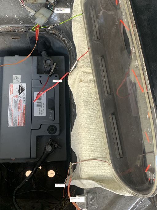
I than rigged the cluster to the sender wires as per the pic below
Brown wire from sender to earth R7
Green wire from sender to L1 pulse
Red wire 12v+ to L7
With one wheel jacked off the floor (it was spinning as I have slight engagement from the torque converter) the speedo worked.
Note only when I added another earth to the mix
if you have read this far and know why I needed to add another earth to the mix please let me know.
I thought I had it sorted and added the another earth to the brown wire from the sender and reattached the cluster but the speedo didn’t work again.
this is as far as I have got so any advise welcomed.
Your last message is difficult to understand. You shouldn't need to add another ground; You should just restore connectivity.
This is the wiring from the cluster to the reed switch (sensor). I found a diagram for the 1979 American import version of your car. It seems that you have discovered most of wiring paths:
Sensor green wire - T2 - H2 - Cluster 11R - continuous ground
Sensor brown wire - T1 - H1 - Cluster 1L - signal alternating ground
.
The speed sensor at the rear is a magnetic reed switch that opens and closes. There are two wires to the switch. One is brown (obviously some kind of ground) and the other is green which is the signal from the switch. The colors brown and green do not matter for correct operation of the sensor switch and the green wire in the 1979 USA version is flipped so that it is receiving continuous ground on T2 and the brown wire is providing a signal on T1. No problem since it still works.
The signal is alternating ground (eg. GND - open - GND - open) which then arrives at the cluster on the left plug pin 1L.
What you discovered is that the ground for the reed switch (via the sensor's green wire) actually comes from the cluster and not from a ground in the rear. Cluster pin 7R is connected to a body ground and it is bridged to 11R which provides the ground to H2 (and the speedo and the fuel gauge, certain lamps, etc). This is the same circuit as T2 which ends up way at the back as the green wire on the sensor (reed switch). The speedometer and the reed switch are directly connected by this ground.
---
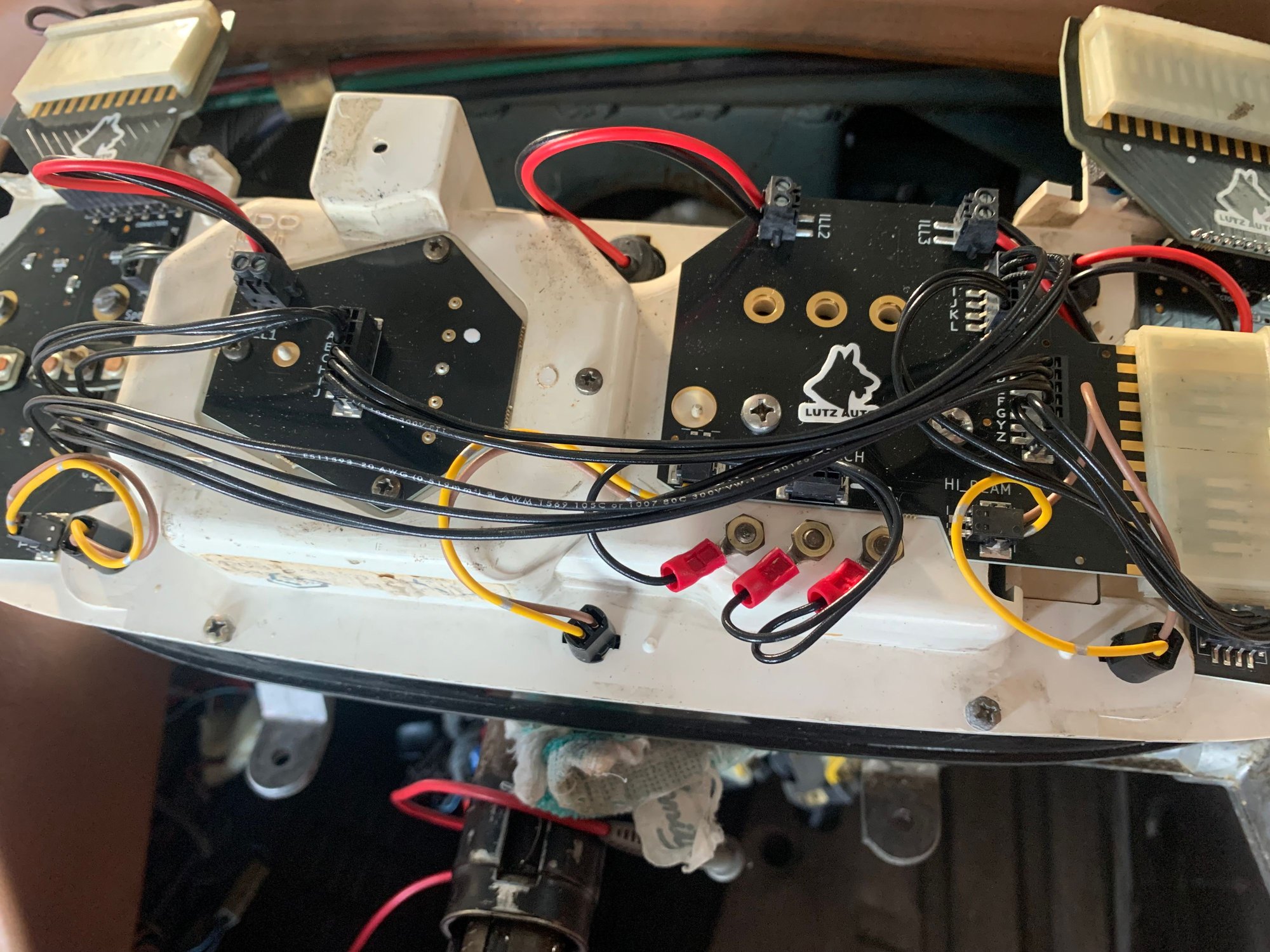
My guess as to why your speedo is INOP is that the plug contacts are damaged or squished at the left plug at pin 1L. You need to confirm that the signal is present on the Lutz board traces from 1L.
If there is signal on the Lutz board then there could be an issue with the connection from the board to the gauge. With the cluster attached but loose (not in the pod), check the presence of a signal to the silver pins that poke through the foil on the back of the cluster (on pic as red dot and line). Those pins connect the foil to the speedo - if any are damaged then your speedo won't work. If you had foil I'd recommend checking the rivets (red dot) but I don't know how Lutz handles connecting the signal on the board to the gauge.
Maybe you should call them up and ask for product support.
Thanks so much for this information - what I learned today
I have a signal to the speedo from the green wire in boot to speedo pin.
I have continuity between 7R to 11R
I do NOT have a signal to 11R
At plug H1 and H2 I get on/off continuity when I turn the wheel
I did not get on/off continuity at L1 and 11R
So I unplugged H plug from CE connected test wire
H1 has continuity to L1
H2 has no continuity to 11R
If I read you comments correctly I should have continuity H2 to 11R
Is my next step to bypass this wire some how?
Pic for reference white dots
L1
R5 and R11
Speedo pin
At the cluster, plug pin 11R is a constant ground. It will not pulse ground. It is not the wheel rotation signal. It provides the ground to the sensor which then "pulses" it on and off.
I marked up the 1979 USA version wiring diagram with some colors. This shows that the ground being pulsed comes all the way from the instrument cluster.
Do not expect a pulsed ground signal at 11R - expect a constant ground.
To do this check, you need to disconnect the RIGHT plug from the console. Go to the Central Electric Panel and unplug the "H" plug.
Inspect the silver fingers inside the console plug for damage. Check the H-plug as well for mechanical damage.
With a continuity tester or a multimeter set to measure resistance confirm that there is a connection between the right console plug 11R contact and contact #2 in the "H" plug.
If there is no connection, the best thing to do is to use an endoscope to inspect the loom. The loom is wrapped in fabric tape (Tesa Tape) and will show signs of burning if there was a short. Alternatively there could be some damage to the loom when someone tried to repair or install something like a radio or alarm system.
Thought question: If there is no continuity between the console plug 11R and the H2 plug at the CE Panel, how does the reed switch sensor in the back get it's ground?
Last edited by copperstew; Mar 28, 2023 at 11:31 PM.
I have a signal to the speedo from the green wire in boot to speedo pin.
If you have a pulsed ground signal to the speedo pin (#2 from cluster bottom, adjacent to your dot) on the back of the console then you are almost there. You can assume that the gauge works since you just had it serviced.
If you have a Power Probe, it can make this next step easier, but this check can be done with a multimeter. Check the pins that poke through the foil behind the cluster. You have already confirmed that a pulsed ground signal arrives at the speedo pins on the Lutz board. Now, check the other pins:
Confirm that there is +12vdc on one of the other adjacent speedo pins (lowest one, #1 from cluster bottom, below your white dot). Use a multimeter to read its voltage with the red lead.
Confirm that there is ground on one of the other pins (above the signal pin, #3 from cluster bottom, above your dot). Use the same multimeter's black lead.
.
If you have +12vdc, a pulsed ground signal and a ground at speedo pins 1, 2, and 3 then your speedometer is functional. Congratulations.
---
If you have all of this and still no speedo, check the long pins that connect the board to the gauge by taking out the gauge and confirming connectivity. All of this assumes that the USA cluster and wiring is the same as the ROW version.
Last edited by copperstew; Mar 29, 2023 at 12:08 AM.
Arr yes the Aussie budgee smuggler - but no, just a speedo that’s putting up a fight.
Still not working but getting closer and a much better understanding of the 928 wiring, thanks to the above threads.
I have now got power, pulse and earth to the Lutz board so will remove the speedo and test the pins over the next week.
Some success maybe
As per the attached short vid I have connected Pulse 1L, 12+ 11L and 12- 11R from the connectors to the back of the new Lutz board and get the speedo to work.
My problem is if I fit the connecters directly to the Lutz board it doesn�t work, do you think this suggests one of the other pins might be shorting.
Pleased to make some progress but not really sure where to go to from here - so open to ideas.