When you click on links to various merchants on this site and make a purchase, this can result in this site earning a commission. Affiliate programs and affiliations include, but are not limited to, the eBay Partner Network.
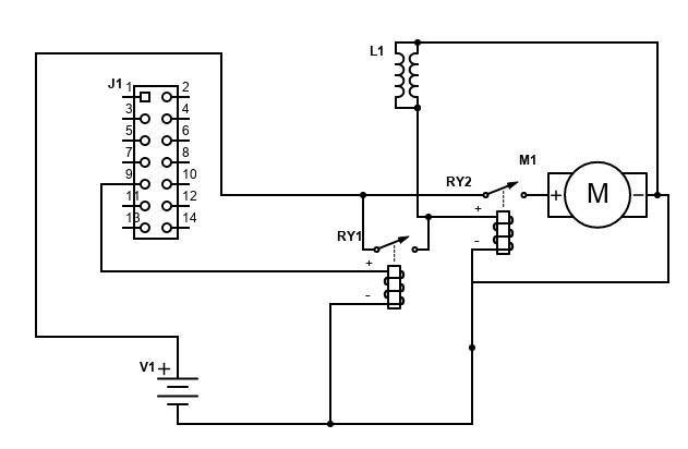
I still have the original undersized AC relay in my HVAC control head. To take some of the burden off of it, I plan to tap into pin 9 on the 14 pin connector and use the output from the undersized relay to trigger another relay mounted to the underside of the bracket that holds the 14 pin connector. I would then draw power for the AC compressor clutch off the jump post. I also thought that I could also use the compressor clutch power to activate yet another relay that would supply power to the pusher fan so that fan is running whenever the AC is on.
Schematic is below but I know it is lacking EMF or "flyback" protection for the fan, relay coils and the compressor clutch (which I imagine needs something as it is a big inductive load). I have seen both resistors and diodes used for this purpose with fans and have used diodes for relay coils. Know nothing about the compressor clutch,
ExclamationA/C and rad fan” Is the post I wrote back in August doing something similar, with the car relay just driving a relay for the clutch, also I hope to put in a big pusher fan that will run with the compressor. My A-C repairman says the more air flow over the condenser the better the system works.
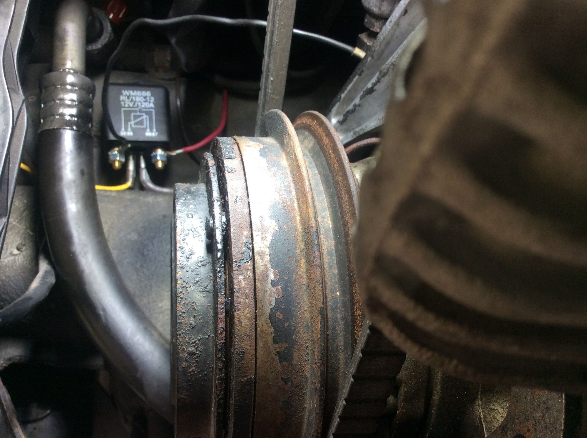
Mounted under the post A 120amp relay should handle the compressor and an aux fan easy!
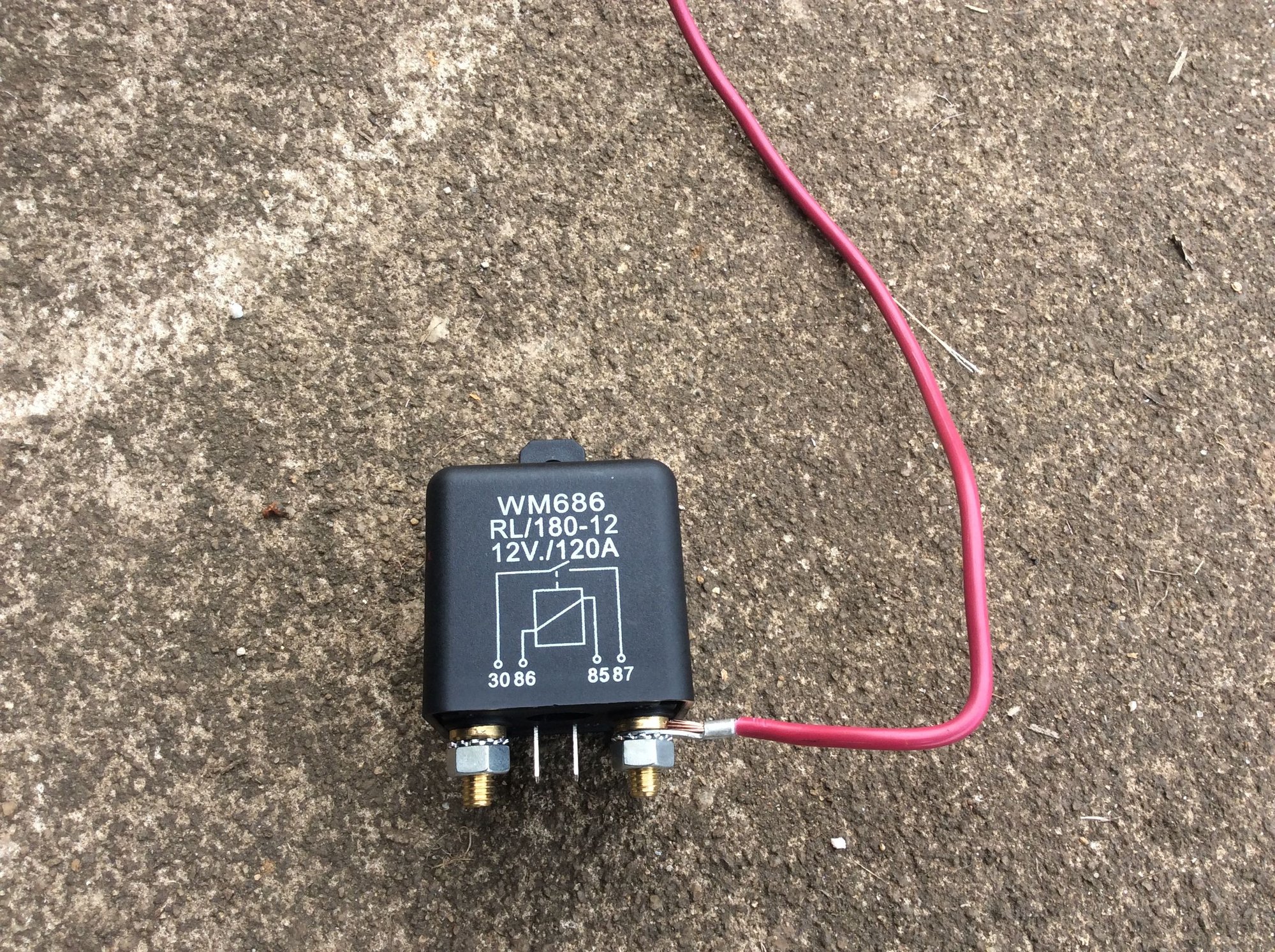
Just use one big relay 40A-50A(+) SPST contacts and drive both the fan and AC clutch together (In parallel). The fan motor will act as a bit of a snubber for the clutch solenoid - simpler and will work fine.
e.g. something like this is more than capable enough:
Just tap into the refrigerant temp sensor connections on the top of the receiver/drier. It uses 2 common spade terminals you can connect to. Bypassing that will activate the factory pusher fan relay already in the car.
So all you need to do is just send power through the relay connected side. No need for an extra beefy relay and overly complex wiring. Just wire the clutch and the fan relay connection in parallel.
I personally added an inline relay as well to my AC clutch in my 81, but hid the wires inside of the bulkhead. Still powered it off of the jump post and just used a spade connector to connect to the factory spade terminal on the FOE harness.
A great upgrade that definitely will extend the life of the factory head unit. Plus it is easily reversible with no cut wires.
Another convert here....doing this keeps you from having to replace the relay on the board...I powered off the jump post as described above and use the wire from the climate head unit to trigger a 40 amp ice cube relay from O'Reillys..I like that relay on Amazon though...thats nice Alan..I see an upgrade in my future....It also powers the AC trigger lead for the electric fan controller...and I put a new pusher 14inch..although the original one ran...once I got it out I gave it a spin...it didn't move very easily...so I would advise not using the orig. pusher fan to run with the AC compressor...replace it...wasn't designed to run that way anyway...
my stuff is mounted on a small board under the ignition coil..nice little space for it there...and plenty of ways to gracefully route wiring.
.now is the time to also focus on the freeze switch...it does the cycling to keep the evap. coil from freezing up. It also benefits greatly from not having to carry the electrical load...just like the climate board relay.
Regarding the question of where to place a snubber diode, they're best placed as close to the source of the back EMF as possible.
in the case of a relay coil, some come with the diode already built in, but you could put it on the connector with little difference in effectiveness.
Many compressor clutch connectors from EFI equipped applications also come with a snubber diode in the connector, but when adding a diode you can use a bare diode such as a 1N4004 or 1N4007, or a socketed diode such as an AC Delco 12135037 that uses a mini fuse socket.
Just remember that if you have a diode on a coil, that circuit is now polarized since applying the power incorrectly will then just short circuit through the diode. (If being driven by a switching transistor, that short will usually blow the transistor.)
In this case for 85+ cars the suppressor is already built in on the CE panel (as long as you didn't remove it - (put it back)) attached to the head unit relay output - so that new relay coil is well protected. Protecting the new relay switching terminals when opening is the place to worry about, snubber diode, parallel mostly resistive load, large cap etc.
In the stock case - if the suppressor is missing the clutch line can see some significant spiking - any electronic PWM fan controller might not like that - so always check its there if you plan uses like this.

 07-04-2022, 06:01 PM