When you click on links to various merchants on this site and make a purchase, this can result in this site earning a commission. Affiliate programs and affiliations include, but are not limited to, the eBay Partner Network.
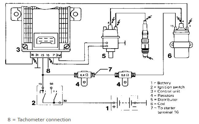
Nothing is normal with this engine. I figured the distributor and coil might wire like a Chevy but it appears not. I’ve found a bit of info, including the wiring diagram attached
and some posts but need a bit more info to wire this CIS engine into my hot rod.
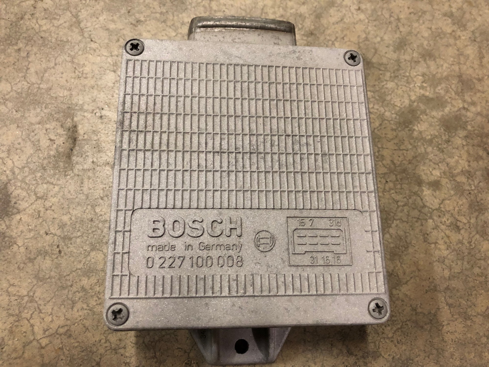
It appears besides the distributor and coil I need an ignition control unit, probably Bosch 0 227 100 008 R23. Correct?
On Ebay there are several Bosch ICUs for around $30, smaller with 8 pins and for later 928s, can I use one of those, or do I have to get the original old one (old and crusty and $100+)?
Can I just use any resistors, w/ resistance as marked?
Can I use any coil? I replaced my coil on my ’78 years ago, and I just checked, it’s chrome, so I’m sure its generic. ??
It looks like you take a wire off between the resistors and send to the starter? What is this about? My starter, and any starter I know of has a big power wire.
-- You'll want the original-style ignition box, one set up to use the Hall-style sensor and pickup in the factory distributor. Options for you might include fitting a different pickup and reluctor (star wheel) inside, and using a system designed to work with that sensor.
-- The resistors in the coil power feed are there to protect the coil from voltages over 12, and limit the current slightly. You can use any other resistors that match the specs of the originals, remembering that they will be carrying all the ignition coil current.
-- Use the coil that matches the ignition box you use.
-- The connection is FROM the starter, and offers a way to bypass one of the resistors while the starter is cranking and system voltage is reduced. That will help the ignition system offer full spark while cranking. There are some threads on replacing that starter contacts with a relay, along with a dedicated primary wire from the battery cable connection at the starter. to give you the same function. The threads are focused on people using the aftermarket IMI mini-starter, which works well on the later cars but is missing that aux contact used in the early cars.
Thanks Much Dr. Bob. I'm almost there. There is a coaxial wire from the distributor, I assume the shield outside wire goes to terminal 16 and the center goes to 31d, correct? Also my distributor coax is separated into two small mail blade terminals, but the ignition control module that is on my existing 928 CIS car and also the only one I discover for a CIS car has big male spade terminals to connect to. Is there a jumper harness I'm missing, or do I have the wrong control module?
Lastly I suspect the positive coil wire goes to terminal 15 and the negative coil wire goes to terminal 16, correct?
first i assume a "typo" ...distributor wires go to 31d and 7
the shield outside wire go's to 31d , the center wire to 7
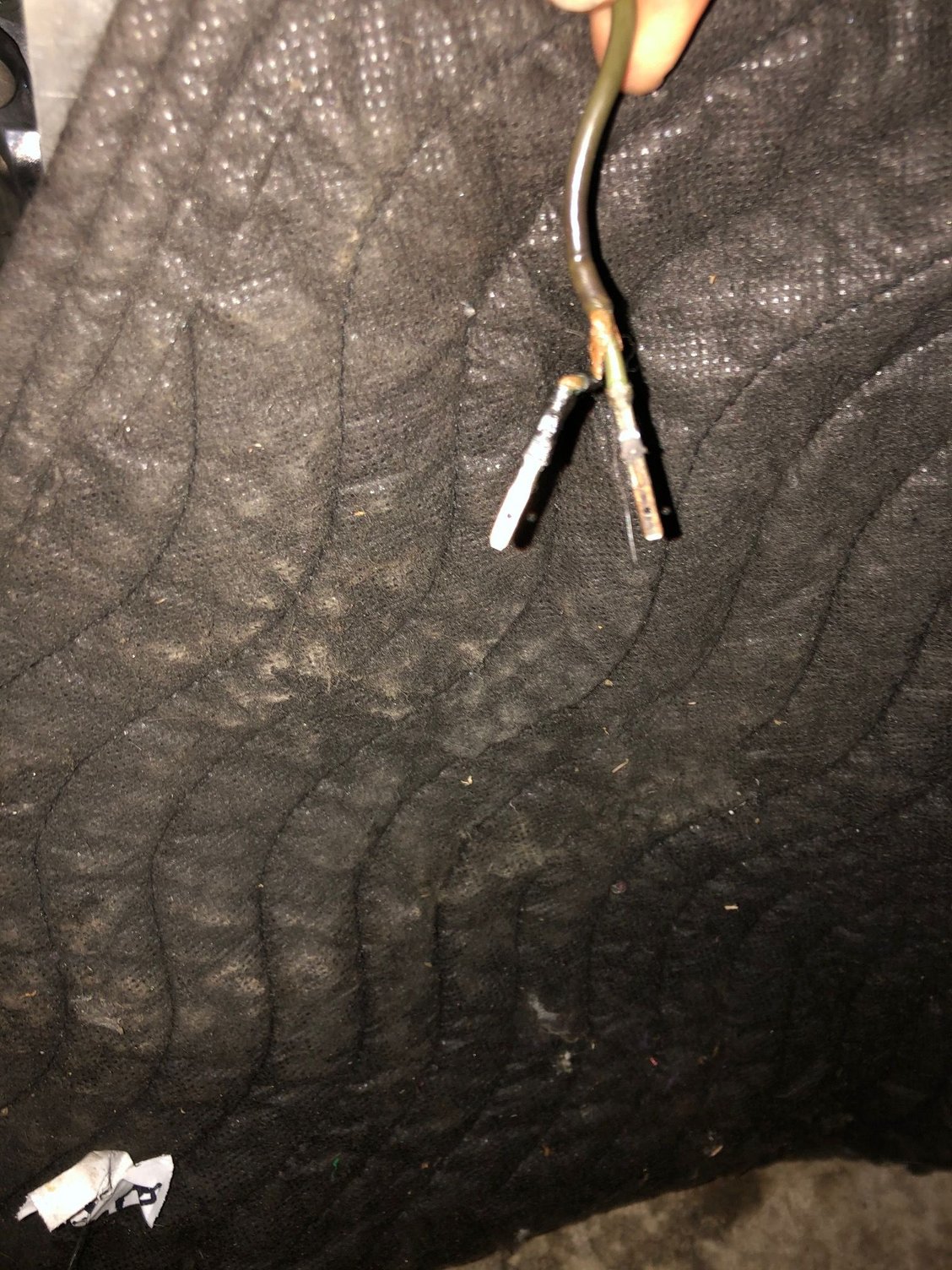
The "green" distributor wire ends in a "Bosch" type connection , the other end disappears in the oem wire loom to end in a single plug for the ignition box .
You show the right box , Bosch 0 227 100 008 for the 16V engines with single distributor
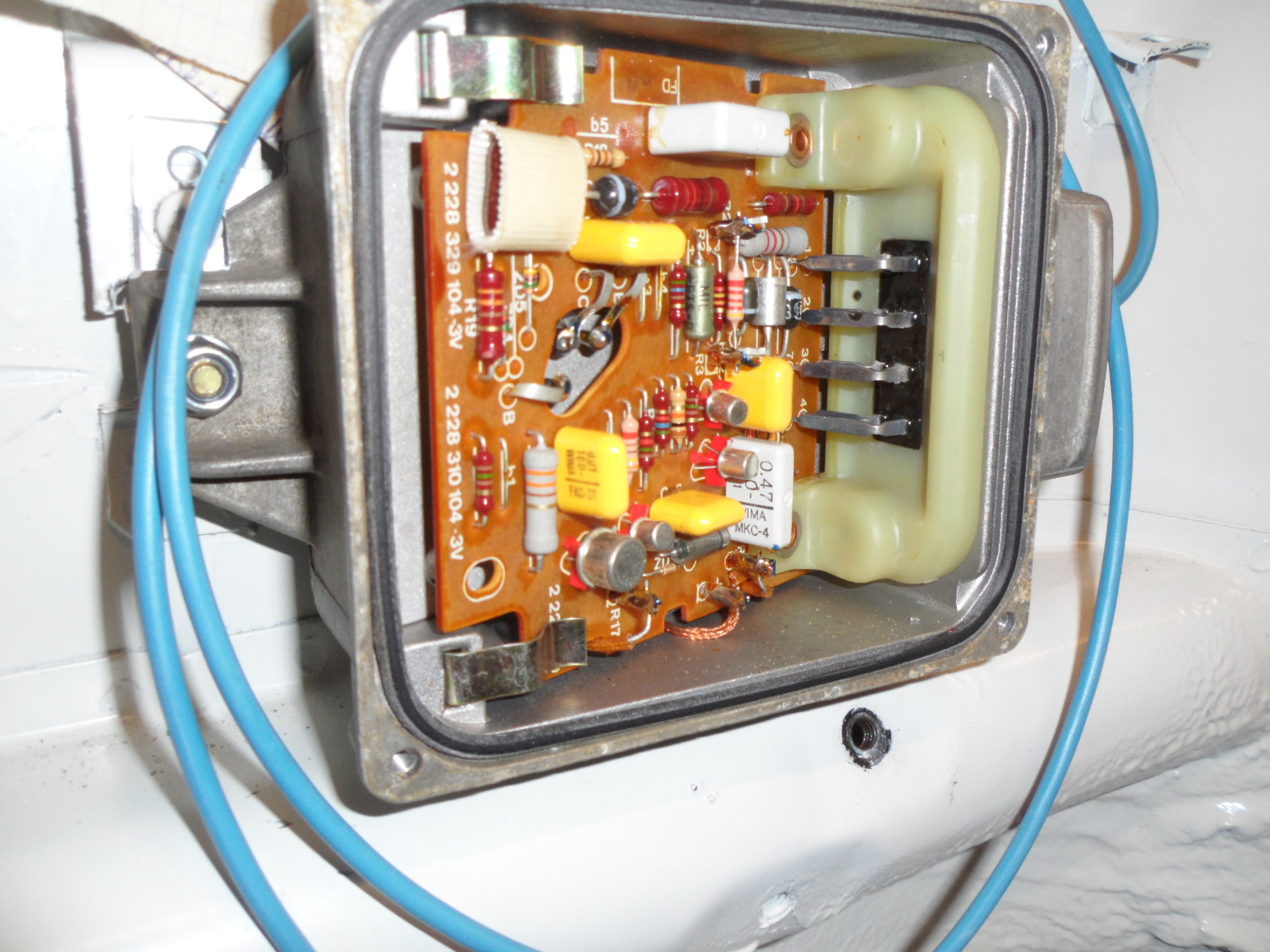
here you see a oem ignition box plug , you can see both wires ( it stays a shielded wire inside the Porsche loom , even for that short distance. )
what i was searching here on the forum was which "16" is coil and which is tacho.....you can't see it on the box..... we found that the "16" in the corner is the coil.
Now with that cut open plug i also see that the "corner 16" is heavier gauge wire then his neighbour , clearly the tacho "16" as this would be obvious being only a thin wire
Thanks Belgiumbarry, all clear and you are correct on the typo. I’m guessing the two terminals marked 16 are simply connected inside the box so it wouldn’t matter which is which but with these cars who knows. I’ll connect them the way Porsche did. Th only thing not confirmed now is my coil terminals are marked + and - I would guess the 15 wire connects to coil + terminal and the 16 connects to coil - Can anyone confirm this?
That is correct Matt , the 15 wire is + for the ignition box as well as for the coil ,now over 2 resistors, ( live when ignition key is "on" ) and the - coil comes form the "corner 16" .
12V + signal also comes from the starter motor to between the resistors ,to give the coil some extra power ,while starting ( and car voltage drops due starting ) . Let's say our coil works on "9V" while running with the 1 Ohm resistor (in total) before it . There are real 12V coils , who don't need those resistor(s) .... but that remains in a circuit with the ignition box... and i don't know if that box can handle it ????
For my rally car build i used 2 resistors of 0.5 Ohm ( which were available ) ... but i guess that won't make "the big" difference .
Don't assume the "16" are bridged inside .... sure not visible , they both have connections to the print .
Last edited by belgiumbarry; 09-15-2020 at 02:28 PM.
Perfect. thanks. Not sure why Porsche gives the terminals both the same 16 label, but there are certainly many mysteries associated with this car. Thanks to you and others for unraveling enough of those mysteries so I can make this hot rod run.
after all , it's not Porsche , but Bosch who called those 2 terminals "16".
As it is a one plug connection on the ignition box , for maintenance /repair /new , nobody could make "the" mistake.
It is "we" , building from parts , that need to understand which is which....
Just still curious... are these two "16" labeled pins connected together internally to CDI module or not ? Externally they go to different places (coil and tachometer)...


 08-30-2020, 09:07 PM