When you click on links to various merchants on this site and make a purchase, this can result in this site earning a commission. Affiliate programs and affiliations include, but are not limited to, the eBay Partner Network.
1983 US model here. Trying to troubleshoot HVAC system. Using the Porsche Service Manual For HVAC WKD 455 020. On checking the inside and outside temp sensor, It calls for testing the sensro outputs for a varying degree of resistance based on the presence of warm air (resistance drops as air temp increases). Here is my conundrum:
The manual says that Connector 4 and 5 (both are 4-pole connectors), I should have a pair of yellow wires for the sensor leads. I do not have two 4 pin connectors with yellow wires. I do have one with a pair of yellow and a pair of orange. If I am reading the schematic correctly, the sensors create a loop from the Temp selector slider on the control switch, to the inside sensor, then from the other side of the inside sensor to the outside sensor, and from the other side of the outside sensor to the HVAC control unit (mixing motor).
The feed to pin 4 of S2 (on the mixing motor) does indeed come from what seems to be pin 4 of connector 4 and is yellow. I would think then that the other wire in the harness (pin 3) would then be the loop to the inside connector, but there is no contiunuity to either of the orange wires.
Any thoughts? I will add a few pics tomorrow. I have looked at the current flow diagram from 81-83 and the wiring diagram for 84 to see if I could piece any of this together but so far no good. Need to figure out if the problem with the motor is sensor related or control head related.
What is your problem? Does the mixing motor go to full hot when the temp slider is set anywhere but max cool?
Check the external temp sensor connector. I think it is common for this to lose contact. Either cut it out and solder the wires together or cut and make your own connector.
Mixing motor does not move during normal operation. Sits at coldest setting. Based on manual, no values (Ohms) coming from control panel or either sensor are anywhere close.
If I open the motor up and manually move the gears say midway around, as soon as I plug it in the cam moves right back to coldest setting.
I unplugged both of the sensor harness connections and added a resistor across the terminals to "simulate" the average reading from each. No change in operation.
Pulled the mixing motor again and disassembled. All gears and motor turn freely - no grease/gunk buildup. Resoldered all components - the diodes on the small board for the heater valve looked particularly suspect.
Pulled the control unit to test. Values of the temp selector are just about perfect when measuring on the bench. The distribution lever (defrost, floor vents, dash vents, auto) has always operated fine.
Plugged the Control panel and Mixing Motor back in. As soon as I turned the ignition and control panel on, the mixing motor started moving all the way (I had purposely moved to about the halfway point) to see what happened. The movement would stop when I would slide the temp selector hard left (Max AC microswitch engaged). As soon as I moved the temp selector off of that switch the mixing motor started running again until it reached its stop. It will not move now regardless of where the temp slider is.
So - now back to testing of the sensors themselves.
Has anyone tried to replace either sensor with a modern thermistor with the same ohm rating by temp?
Be glad to share some of what I have learned to help others who may be going down this path. So here are some notes and a few pics.
One thing that caught me right out of the gate was the wiring harness behind the console. When I started I was working with the console still installed (even the WM makes a point of being able to do these tests without removing it - much easier to sort out with it taken out - but keep it close by.
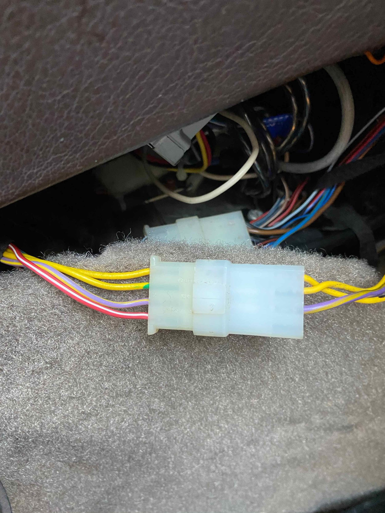
There are FOUR 4-pin connectors behind the console. Two of them have yellow wires in the harness. Plug 4 has the two yellow wires plus a red/white and purple/yellow. It is the connector for the
Plug 5 has the two yellow wires plus red/white and brown. This is the connector to the INSIDE temp sensor. The Red/white and brown wires send power to the little fan motor on this part of the harness. One main difference here is where the harness components originate from. The harness for the outside sensor comes in along the tunnel and up near the gear shift lever. The mating connector is part of the harness that is strapped in to the dash behind the console. The inside sensor harness also comes out of the HVAC harness behind the console, but it plugs directly into the temp sensor.
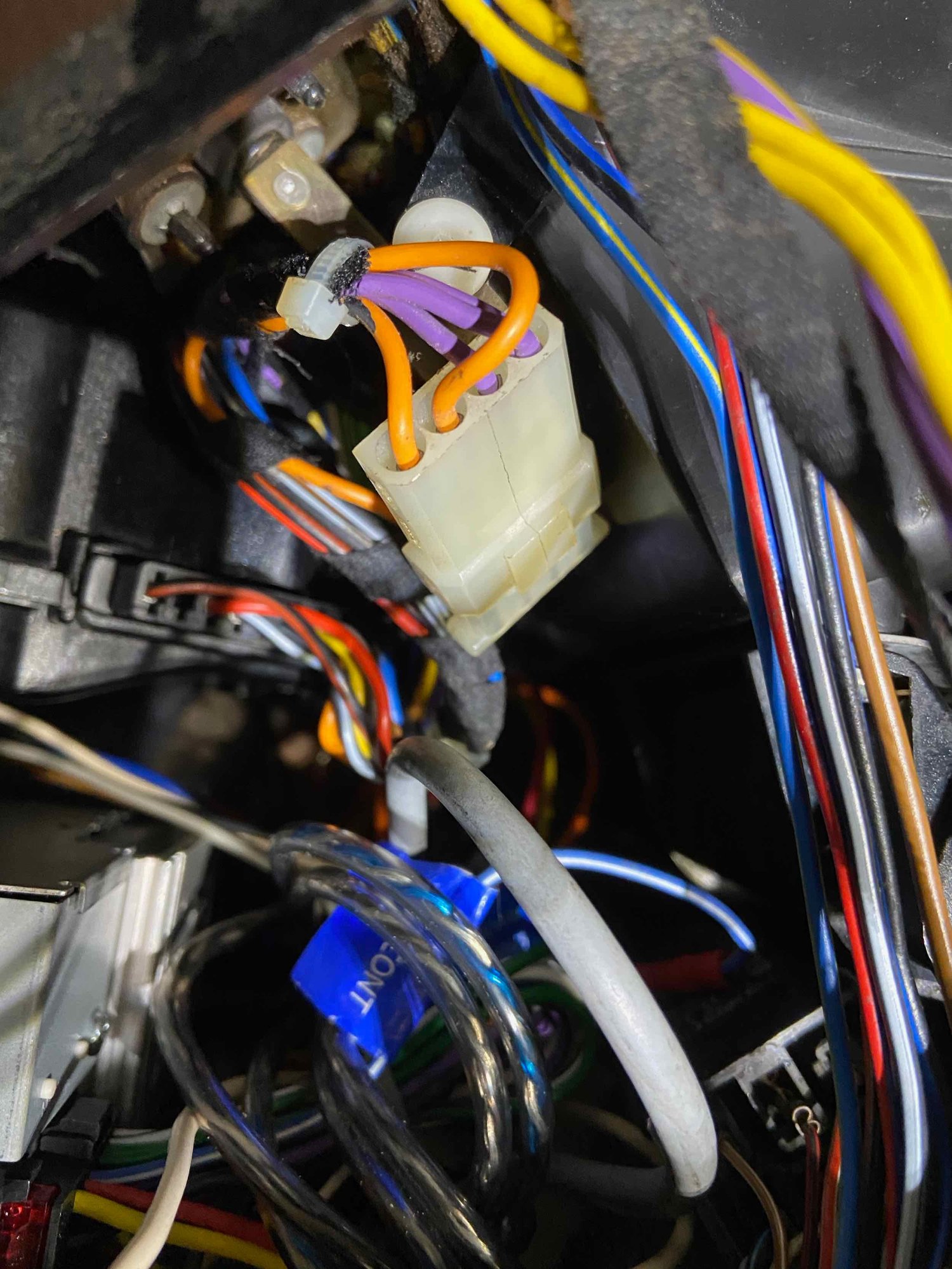
There is also a 4-pin harness (Plug M) that has brown and orange wires in it. This connector runs from the HVAC harness to the microswitch on the center vent. The last connector is one of the plugs for the '!' sensor panel and reset.
Some pics...
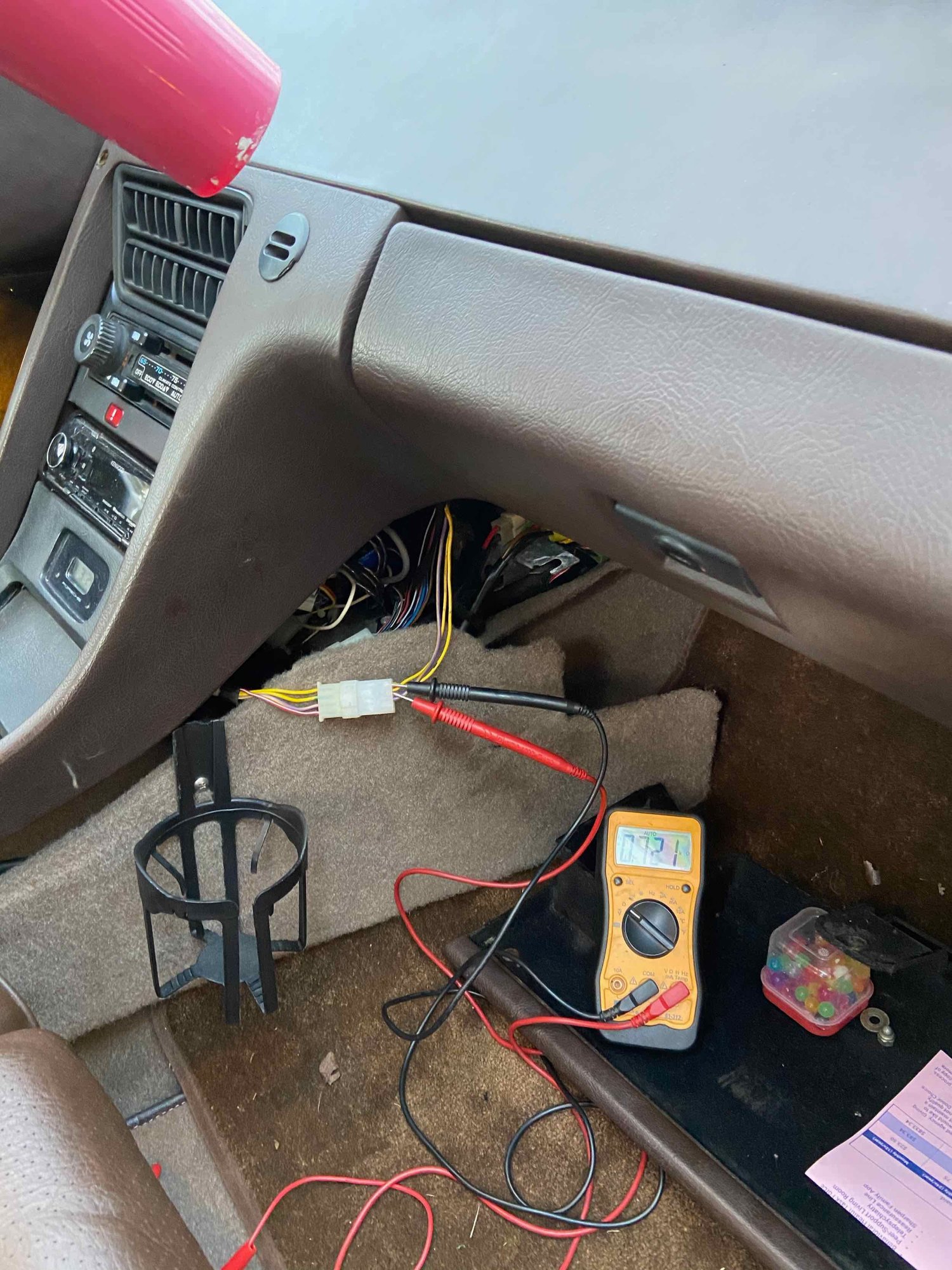
Plug 4 - this is the connector for the outside temp sensor. The part on the left comes up from near the gear lever from outside of the car. The right side of the connector runs to the HVAC harness behind the console. Note there are only three wires in the right side of the plug. Testing the connector. This is how to test them all...here looking for resistance to verify operation of the outside temp sensor. The close connector to the phone is Plug M - which runs to the center vent nozzle microswitch.
In the middle pic above, the reading on the meter is .761k Ohms, which is 761 Ohms and is about right for the outside sensor (it was probably 50 some odd degrees outside). If this sensor reads anything other than a number between around 400-950 ohms, then the sensor is either bad or there is a broken connection somewhere. The plug in the wheel well that connects the sensor to the harness is notorious for getting gunky and corroded.
All of these figures are in the two HVAC Service manuals that I have - one published in 1980 and one in 1985. The 1980 manual is great because it provides more detailed breakdowns of the wiring colors, plug arrangements, and termination points of the wiring instead of just the diagrams. From what I can tell, the wiring colors are the same for HVAC from 1978 through at least 1985, and maybe into the S4 cars.
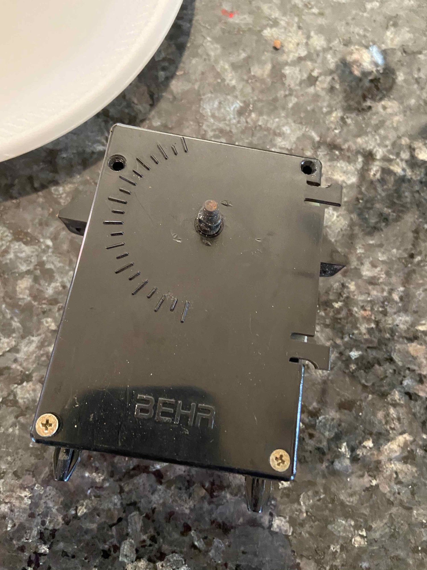
So - finally verified that the sensors were in spec. Next was the control unit itself. I pulled it apart and did an inspection visually, and tested the connections for the temp slider pontentiometer outputs. I suspected this because the value coming from the temp slider, plus the resistance values from the sensor loop, is what determines the position of the setting motor. I assumed that because the motor was not working it may not be getting a signal (or the correct signal) from the control unit. Everything tested correct, and I had already verified operation of the flaps and vac solenoids, so that left the setting motor.
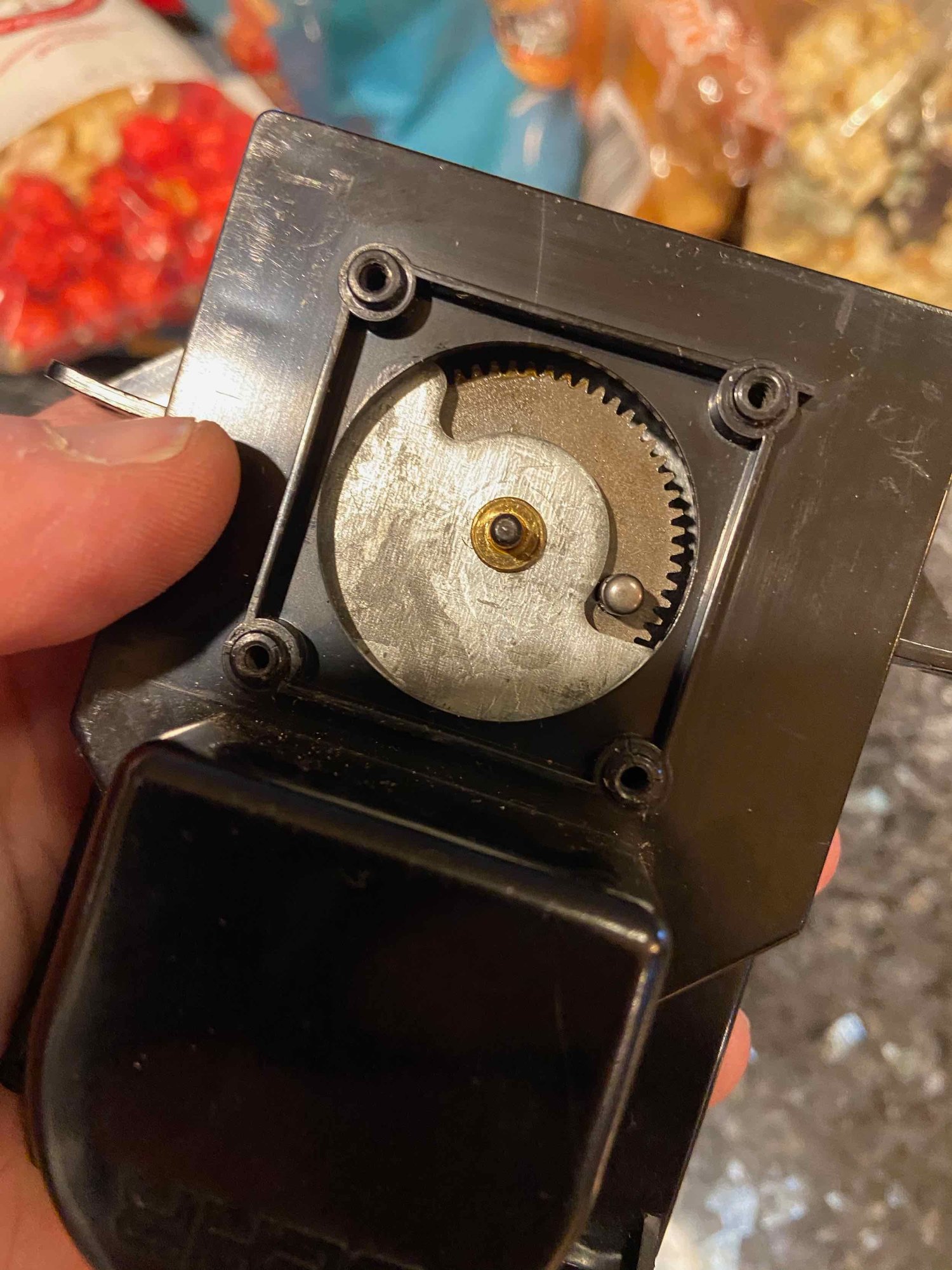
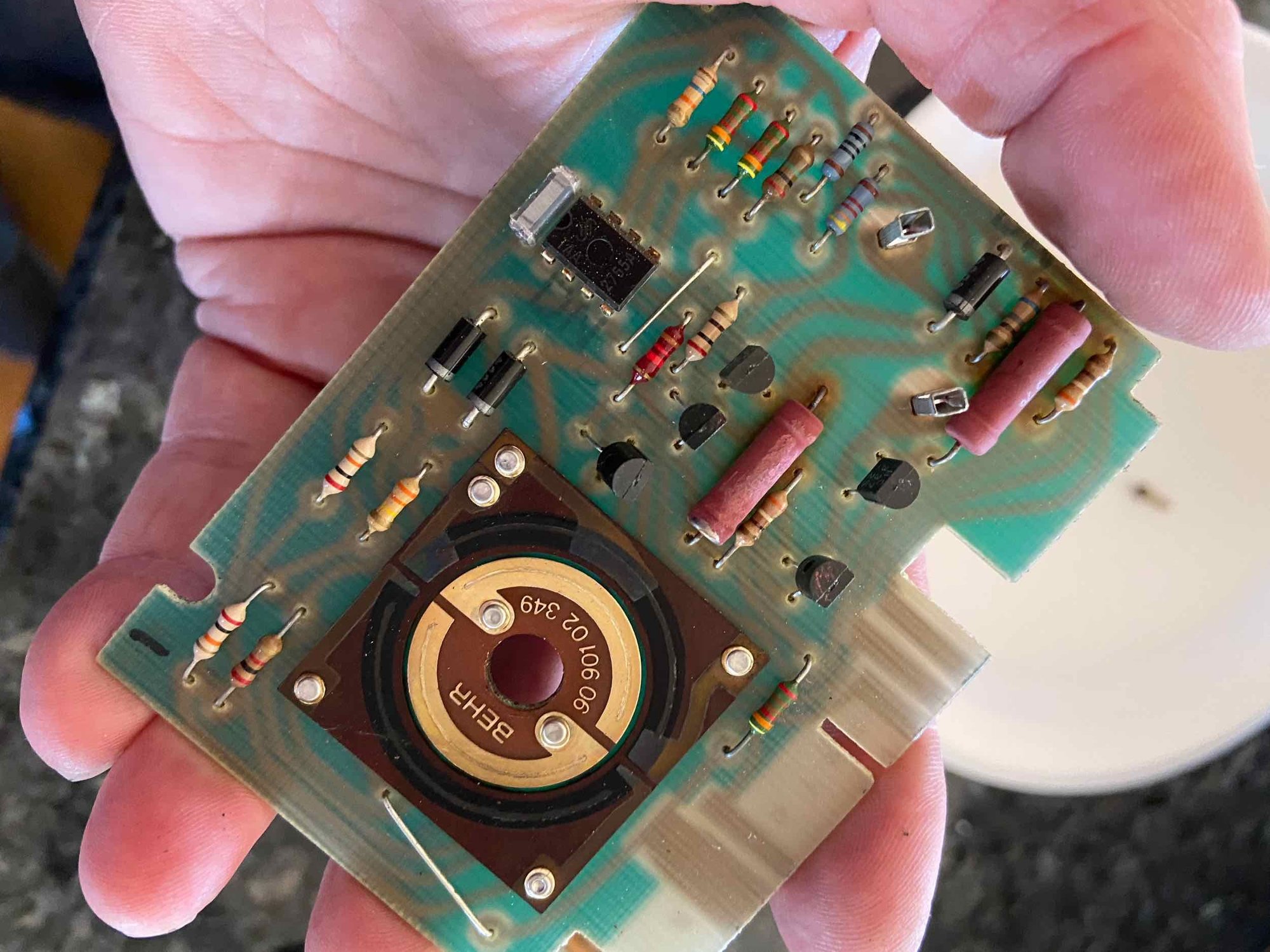
Easy enough to remove that - two phillips screws and two harness plugs (S1 and S2), then the operating cam is attached to a rod that actually moves the flap in front of the evaporator. The setting motor is really pretty simple in design. It has two circuit boards and a motor with some gears. The motor can obviously turn in either direction, and the rotation gears have a stop button built in them that rides in a channel and stops the motor at wither end of its travel. The larger circuit board appears to drive the motor itself and the smaller board controls, among other things, the solenoid for the heater valve, which opens at about 20 percent. Here are some pics. The issue that happens here is there are 4 transistors that drive the motor's operation, and over time these are known to fail. I went ahead and replaced all 4. There is a 5th transistor on my version of the setting motor, but it tested good so I left it alone. The transistors are BC327 and BC337. See notes regarding this with the photos. Here is where I screwed up originally - someone needs to take my electronics man card.
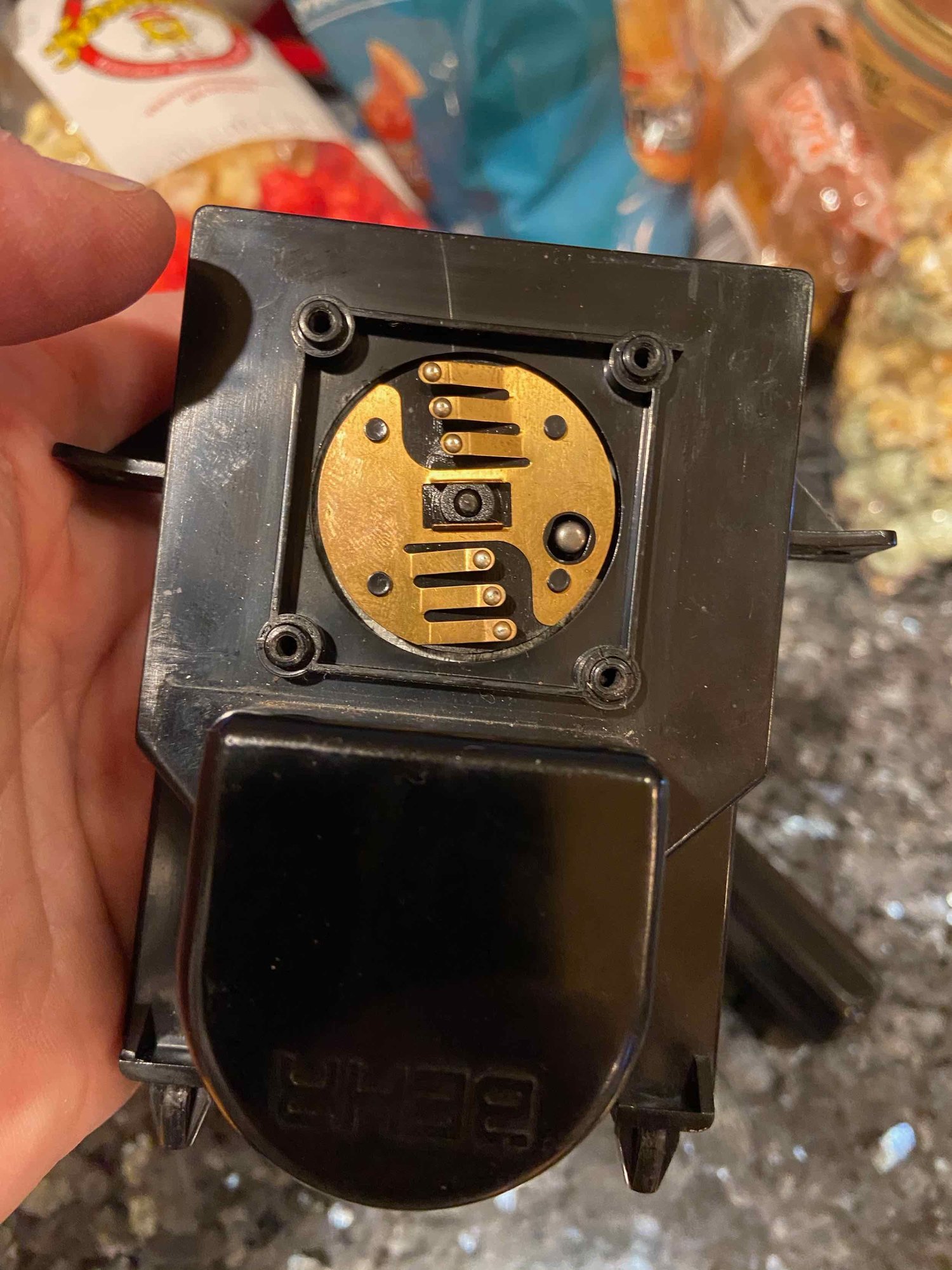
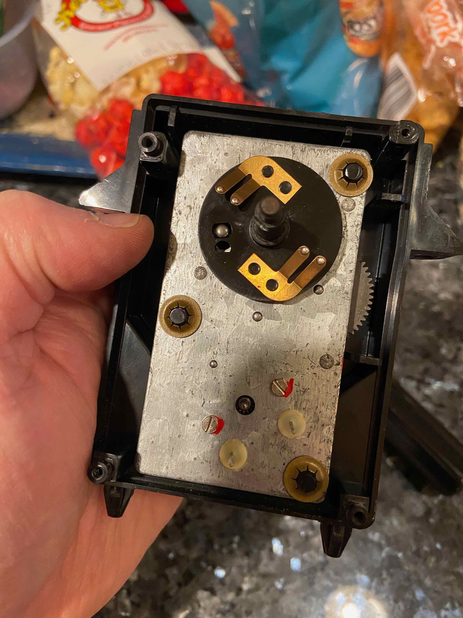
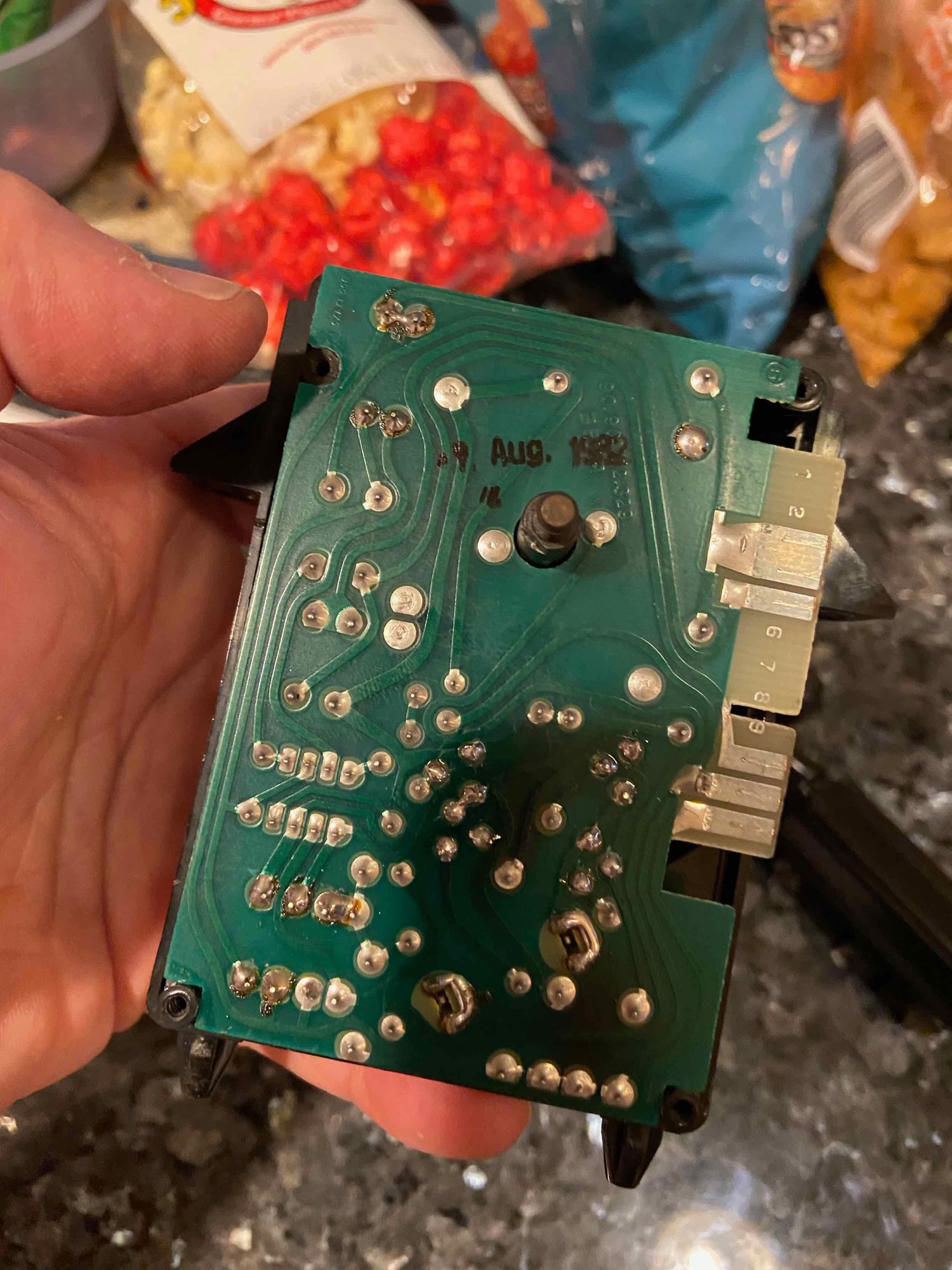
My local supply house did not have BC327 and BC 327 in stock, so we used a substitute from the data sheet. The BC327 substitutes to a 2N4402, and the BC 337 substitutes to a PN2222A. I replaced them in exactly the same way they were installed from the factory...but on the replacements, the C and E terminals are reversed. I realized this in checking the values of the transistors after I installed them. SO - I took them out and flipped them around and voila - everything works beautifully. Some pics: The control unit as it comes out of the car. The drive cam mounts on the shaft with a nut. It is already removed in this photo. 4 screws and the cover comes off. This is the side of the unit that drives the heater control solenoid. Note the little stop on the gear that controls where the unit stops. This is the circuit drive on that side. It has a hole that fits over the little stop, so you can only install it one way. The little fingers ride on the circuit board traces. Be careful with them, if one gets pushed down, it may not make contact with the board and complete the circuit. This is the other side of the unit with the large board removed. To get inside to the gears, the rotating wiper disc slides off of the shaft then the three friction washers have to be pried off - careful as the studs that they are placed on are plastic. Main control board in place. Note the shaft sticking through the board. Plug S2 is the plug on this board. Here is the flip side of the main board and where my issues were. I could not find a schematic for this board, but the transistors to replace are the 4 that make a square on either side of the brown resistor. The fifth one that I did not replace was closest to the circuit contact disc. Note that the two transistors closest to the disc in the square are facing with the flat side towards the connector pins, and the other two have the flat side facing away. In my case these are now flipped.
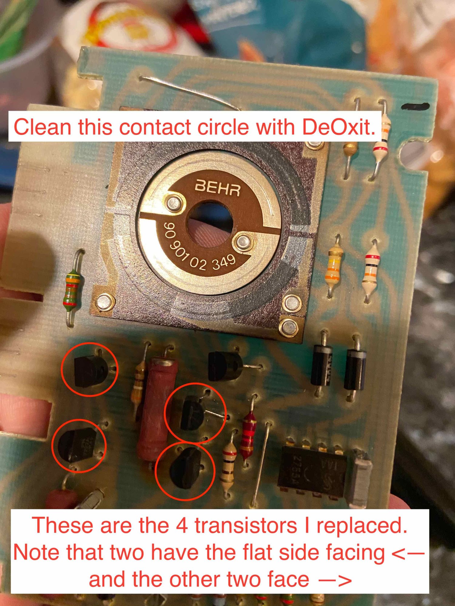
Had a request to better annotate the photo with the components I replaced. Here is an updated pic.
In the picture above, remember this photo is the original layout using BC327 and BC337 components. My replacement components have a different pinout and had to be installed "backwards" from the photo above.

 02-09-2020, 09:50 PM