When you click on links to various merchants on this site and make a purchase, this can result in this site earning a commission. Affiliate programs and affiliations include, but are not limited to, the eBay Partner Network.
has anyone used one of these harbor freight engine support bars? wondering if it would leave any marks where the rubber legs sit?
also, not sure where you would attach the chains to the engine?
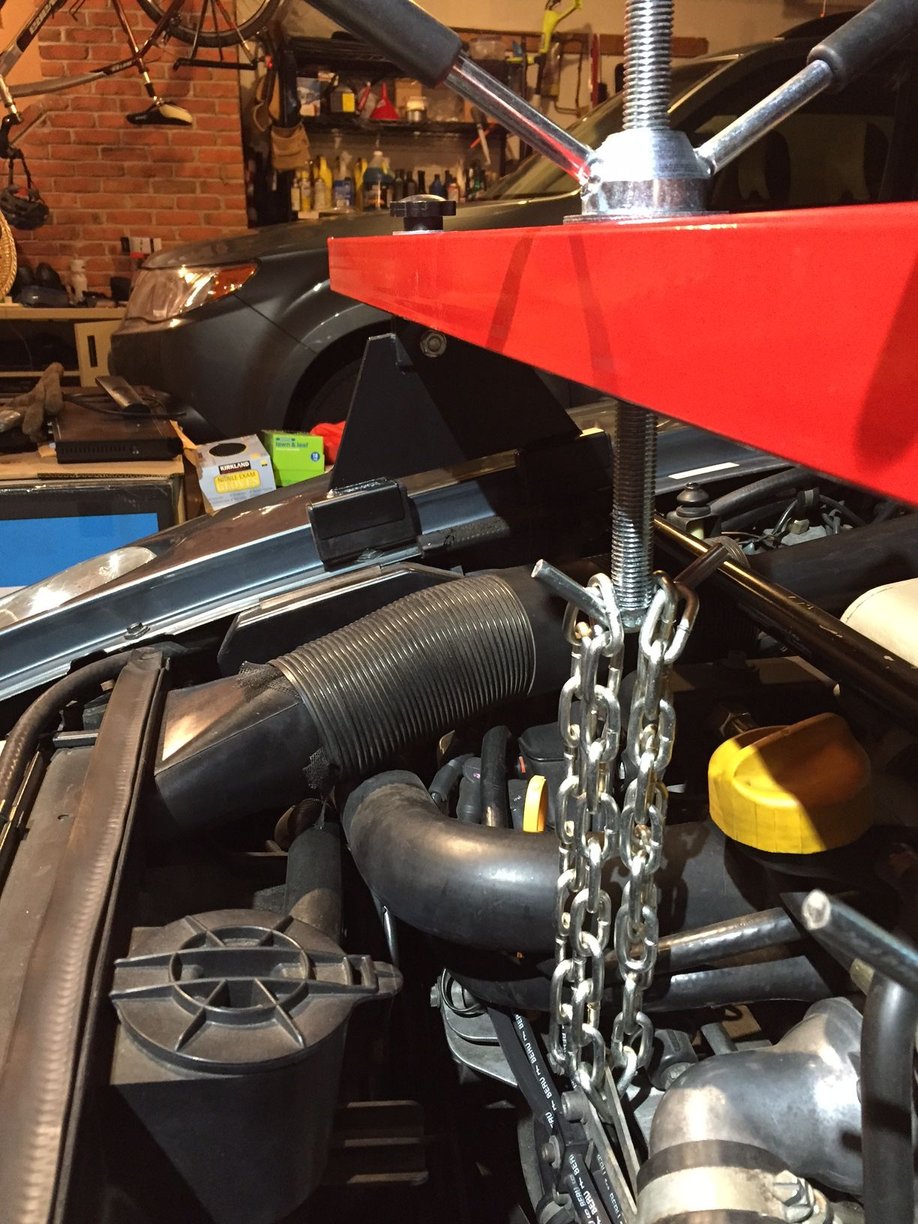
I have one that I used to do the MM/OPG a few years ago (before the cars heart transplant). The legs rested nicely on the fender flanges with some shop towels for scratch protection. I looped the chains through the plug wire support frame. The engine was supported nicely and I was able to get enough additional height to make putting the cross brace with new motor mounts back in (relatively) painless.
I put a towel on the fender, and then a board on the towel. Rubber feet on the board (Captain Obvious, at your service).
I attached the chain (just one) to the front lift ring. I used a removable link ( what I've always called a 'French Link') to attach.
I still had the Bell Housing & Torque Tube attached, so the back of the engine was supported.
Alternatively, Dwayne's MM write up shows his home made version. He uses lumber (2x4 & 4x4) and makes two of them, supporting the engine front & back. I did that also. I was more comfortable with the engine supported that way - 3 points (front ring, back ring & BH).
I have one collecting dust. I took out two fender bolts so the rubber feet could sit where they wanted to be. The pic below shows where the feet wanted to rest during a test fit. Took out the bolt under the forward feet on both sides. No marks. I recommend you contact Curt (Adk46) and ask if he still has his work-of-art wooden support. He made cutouts so no bolts need to be removed (I think the contacts are cut to the same curvature as the fenders).
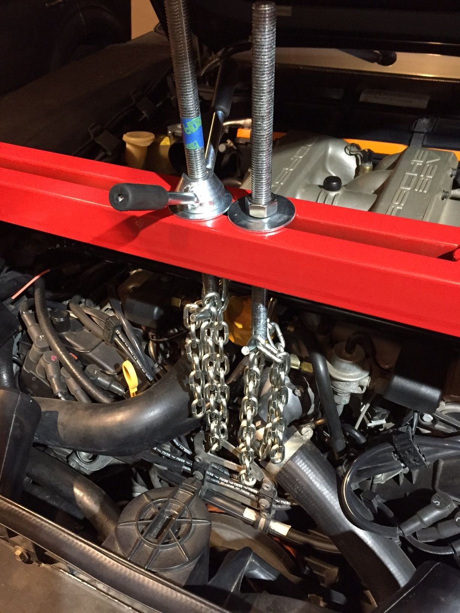
I didn't trust the smallish hooks/welds of just one lifting rod so this is how I actually did the job. Set the level with the left side, then drew the right side down to snug as a helper ( peace of mind). The painters tape was my lift height gauge (about 1.5 inches) and I used the bolt to avoid crank handle interference.
Last edited by Captain_Slow; Mar 3, 2019 at 02:48 PM.
Reason: add pic of final setup
I have one that I used to do the MM/OPG a few years ago (before the cars heart transplant). The legs rested nicely on the fender flanges with some shop towels for scratch protection. I looped the chains through the plug wire support frame. The engine was supported nicely and I was able to get enough additional height to make putting the cross brace with new motor mounts back in (relatively) painless.
I did this exactly. Shop towels protected the fender flanges. It worked just fine with absolutely no damage to the body. Prior, I had used Rob Edwards' similar support on clinic cars with similar results.
My first 928 MM project (on my own car) was done with the floor jack under the sump, then a pair of jackstands under the motor mount supports on the engine after the cross-member and the mounts were removed, to allow the sump to be dropped. This last episode was with the HF support plus the car on the lift, and was amazingly painless compared with that first effort laying on the floor under the car on stands. Experience reminded me to clean everything four times before turning any bolts, so it was a relative cakewalk. I have a used-once HF engine support available to users near here, if anyone needs it. If you get all the cleaning done in advance (4x with engine cleaner...) you can bring your car and use the lift and tools; you will have to put up with my "helpful guidance" during the process.
That�s a very generous offer, and one that I may well take you up on later this year, Dr. Bob!! Motor mounts (and new shocks and upper arms and steering rack bushings) are my next big project on the �83 and frankly one I�ve been putting off without a lift!
I made one out of 4x4 lumber and some scrap wood. The directions were somewhere here, maybe Dwayne. It's an hour of shopping and an hour of building. Worked great.
The HF model looks good too.
Good luck,
Dave
I have one collecting dust. I took out two fender bolts so the rubber feet could sit where they wanted to be. The pic below shows where the feet wanted to rest during a test fit. Took out the bolt under the forward feet on both sides. No marks. I recommend you contact Curt (Adk46) and ask if he still has his work-of-art wooden support. He made cutouts so no bolts need to be removed (I think the contacts are cut to the same curvature as the fenders).
I didn't trust the smallish hooks/welds of just one lifting rod so this is how I actually did the job. Set the level with the left side, then drew the right side down to snug as a helper ( peace of mind). The painters tape was my lift height gauge (about 1.5 inches) and I used the bolt to avoid crank handle interference.
great to hear this bar will not leave any marks; thanks. in these photos, is it ok to support at the very front of the engine? I would think this would create an imbalance? shouldn't the attachment points be more in the center of the cam covers?
great to hear this bar will not leave any marks; thanks. in these photos, is it ok to support at the very front of the engine? I would think this would create an imbalance? shouldn't the attachment points be more in the center of the cam covers?
If the bell housing & torque tube are still attached, the back of the motor is supported by the transmission mounts.
In that case, lifting by just the front lift point is fine. Did it.
The second go-round, I used Dwayne's lumber design. Both front and back.
No appreciable difference that I could see, other than that I had to keep the two lift points 'synched' or one of the chains would go a bit slack.