When you click on links to various merchants on this site and make a purchase, this can result in this site earning a commission. Affiliate programs and affiliations include, but are not limited to, the eBay Partner Network.
First, actually diagnose whether or not your HVAC head is bad as described above. Your 'problem' description is ambiguous. Might be the head, might be the anti-freeze switch internals. Might be the weak spade connectors on the switch body. Once you are sure of the diagnosis then decide on the form of the remedy.
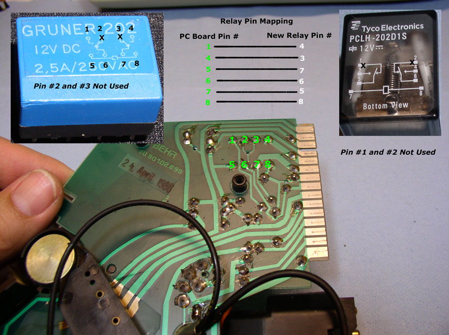
The replacement internal relays are not a direct fit for the OE in-board relay. You have to solder small lengths of wire from the PCB to the relay pins.
As to whether a 10A relay is better than a 5A relay... The circuit needs to carry 3A reliably. It would seem to me that a 5A relay is adequate for the purpose but the current rating above the minimum is not a primary constraint in selection. If you are going to wire an external relay in the firewall plenum then whatever solution needs to be protected from weather. Internal to the head your are size limited. External to the head you are also size and location limited.
Regardless, that circuit needs to be fused to protect both the wiring and the PCB in the head. At this point I fit the in-line weather-protected 4A fuse to every 928 that comes here. There's no way to 'save' the OE 2A relay. They will all eventually die. But, at least you can help insure that the wiring and/or PCB board don't 'release their smoke' as the result of a failure. A mechanical seizure of the compressor (the internals or the clutch bearing) will fry the relay and will very likely fry the PCB. I have also seen one PCB ruined due to the 2A relay dying in the 'normal course' but in some bizarre way.
it is the job of the freeze switch to cycle the compressor? is that why you mentioned that the freeze switch acts intermittently?
(I thought I may have read that the 928 AC compressor is on constantly, and does not cycle?)
PM questions came in regarding some replacement relay options.
-- The suggested Radio Shack relay is NLA, so we get to hunt some more.
-- A question about using a 53B relay similar to what's used in the common places in the car: The 53B is a single-pole relay only, meaning it only switches one circuit. The relay in the control head is a two-pole relay, with the second circuit feeding the engine controls to let them know the idle needs to be a little higher, and the cooling fans need to run on S4+ cars.
-- You can use almost any double-pole relay so long as the contacts are rated for about 6 amps DC or higher. Voltage rating is not important so long as it exceeds battery voltage. Some will point out that the clutch coil draws less than 6 amps, but the coil is an inductive load. Similar to the way an ignition coil works, a voltage spike is generated when the relay opens. The contacts need to be stout enough to withstand the arcing that happens when the coil field collapses, so higher voltage and current ratings are desirable.
I haven't done a search for a relay since I did the upgrade over twenty years ago now. I wandered through a large electronics surplus store up the street from Greg Brown's old location, and found a robust industrial-strength relay that would fit in the space forward of the controller, and had plenty of extra rating beyond the minimum.
. It may be a little bit of a challenge getting it in the small space by the controller head, but can easily be wired with extended pigtails to live off to the side and forward of the controller, in the center console closer to a side panel.
it is the job of the freeze switch to cycle the compressor? is that why you mentioned that the freeze switch acts intermittently?
(I thought I may have read that the 928 AC compressor is on constantly, and does not cycle?)
Remember when testing for voltage at the various points in the system, everything is connected when you test. Looking at the pressure safety switch on my car is possible with jumper sections installed so the boot is not in the way. If you test and find full voltage there but the clutch isn’t engaged, your next test is at the 14-pin on the harness side (top), then the spade connector to the clutch wire. All testing is with everything still connected.
and in post #5, is this photo the pin mapping has a different order? ; in your write up each number matches the relay numbers.
or perhaps I am reading this wrong?
I numbered the pins in my write-up, as the pins on the relay I used didn't have numbers. Your goal is to have the functions lined up so a connection on the circuit board for the old original relay maps to the same function on the new relay. As several guides point out, we are only interested in the Common and the NO (Normally Open) contacts in the relay. The relay has two pairs of these contacts, and it doesn't matter which pair you use on the new relay.
Whatever method you use to keep track of wires and contacts, Be Sure To Write It Down and make a diagram documenting the work. The original "instruction" I shared a couple decades ago now started out as documentation of the modification I made to my own car. It was intended only to go into the docs package with my car, so that some future owner might stand a chance of figuring out what would otherwise be a hack on the controller. The only difference between a bug or hack and a feature is the documentation. Anyway, when others started reporting similar symptoms, I added the troubleshooting section. Others after me, notably Dwayne, added some info for using different relays including what was then a commonly-available Radio Shack part. With Radio Shack now TU, users will need to get a little creative and figure out what will work with a relay they can find.
FWIW, it's possible to use a 53B-style SPST relay for this duty by adding a diode to the output to the fan controllers on the S4+ cars. For most, it will be easier to just use the same DPDT-style relay rather than digging through circuit diagrams for the controller. If you don't know your anode from your cathode on a silicon diode, sticking with the DPDT relay is for sure the easier and safer route.
dr bob, you mention that most DPDT relays will work, but voltage needs to be higher than battery voltage, yet this one, and the 275-218 are 12VDC?
my electrical knowledge is weak, so I am not sure I understand..... what I DO understand, is that Dwayne used the same 275-218 relay, yet his wiring is different, so I am not sure which way to go?
is there a diagram on the old blue relay? that would make it easier to understand
oops! I see the diagram on the blue relay. I would assume that Dwayne's relay mapping is correct, but is there more than one way to wire up the external relay?
dr. bob, your wiring is different, but perhaps also correct?
The wiring in the picture is correct. Separate the wiring into three groups:
1. coil of the new relay(little rectangle) to pins 5 and 8 on the PC board. This actuates the wipers to engage the Normally Open contacts, and pick the clutch, and notify the car that AC is engaged.
2. Wiper contacts which has 12V DC present on it at all times. Pins 6 and 7 on the PC board connect to the wiper on the new relay. The wiper is always the icon with the little bent arms that move back and forth(ignore the connection in the default Normally Closed position as those pins are not used).
3. Normally Open pins 1 and 4 on the PC board connect to the Normally Open pins on the relay. These are the pins which do NOT have the wiper touching them. In the picture, pins 3 and 4.
Normally Closed pins on the relay should be insulated as they have 12VDC present at all times. Pins 1 and 2 in the picture, slide a bit of heat shrink over the pins, and heat until they seize on the pins. This will prevent accidental application of 12V from the HVAC head to anything the pins touch.
As for voltage, it is critical that you get a 12VDC COIL voltage. The pin switched voltage and current rating will typically be 250V or more, and the current rating will be 5 amps or more. The COIL voltage must be 12VDC.
Relay failure is the most likely root cause. The thing works when cold and with heat build up it then packs up albeit the 2 minute timing is not much time to heat things up but given it is a random failure distinctly possible I suppose. Mine used to fail after about 10 minutes of running, I would switch off the a/c and it would re-engage when switched on a few minutes later. Changed out the head unit and installed the slightly different one from my late S4 and problem solved.
Yep that's how mine failed in the 87. I got a direct replacement for the Gunner 220 relay off of ebay Germany for $60.
That will work fine. Coil pins 7, 8. Wiper pins 5,6. NO pins 3,4.
thanks for the help.
moving on, what component is responsible for cycling the compressor? I assume that the head unit relay, once energized by the button, is always engaged and does not have anything to do with cycling?


 01-20-2019, 09:19 PM


 f:0
f:0