When you click on links to various merchants on this site and make a purchase, this can result in this site earning a commission. Affiliate programs and affiliations include, but are not limited to, the eBay Partner Network.
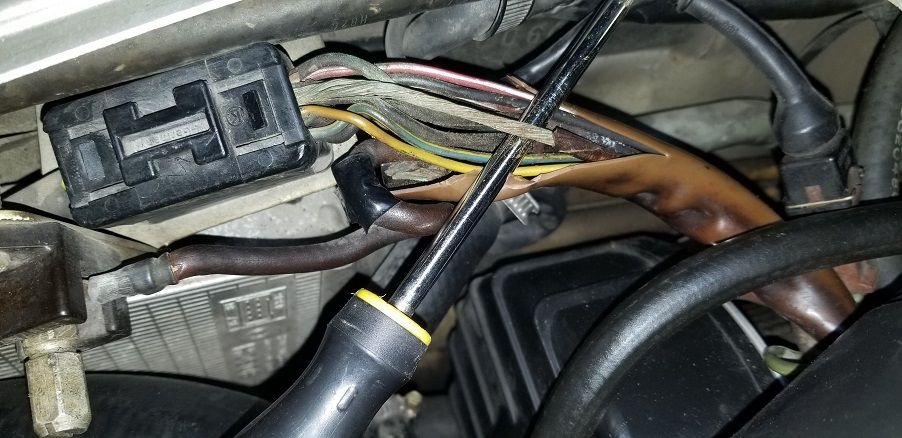
Hi, there fellows, I found the apparent cause of the not turning issue:
So, I am aware that a new harness is available. Even though I had bought one of those $80 or so Astro crimpers with the express intention of doing the harness myself, I will still consider buying a complete harness. For now, my intention is to get the engine to turn and would like to replace the corroded wire. I have run into some problems:
1) I could not find the actual 14 pin connector in the manual's current flow diagrams. I can see the starter wires Yellow and bk/yellow referencing the T14 connector but they don't go to the T14 itself. The corroded wire in mine looks brown to me. Where can I find a more complete diagram/s where the actual T14 and its wires go to? Where does the brown corroded wire go to?
2) Could not figure out how to remove the cover to the pin connector. I tried but did not come out. I am trying not to mangle it, as I have done plenty of times in other instances. Can someone tell me the trick?
As always, your help is appreciated. Mario
you are looking at the 14 pin connector in that photo the wire that has a peeled off insulation looks to be the #14 pin wire,
did you google Porsche 928 14 pin connector wire diagram?
Hello Mrmerlin, I did sure google "1979 Porshe 14 pin diagram wiring" It returned nothing conclusive. The brown color doesn't even show up in any of the many diagrams that pop-up. Perhaps it is not brown on mine. I will cut the sleeve further to see if it shows a different color. I found a few threads on removing the cap on the 14 pin connector, including on Pelican's. I was not sure if they were talking about a different YM.
I'm not an authority on the 928, nor do I have a 79, but I don't see a brown wire in the 14 pin connector diagram that I downloaded.
The only grounds I see from the engine are the "internally grounded" connections, such as the spark plugs, starter, alternator, and the like, which I would assume are tied to the chassis with a heavy ground strap.
If the later cars are anything like my 80's Mercedes, the only grounds that went through the engine harness were sensor returns, once the computers got sensitive enough to require a dedicated connection, rather than relying on the engine block to chassis ground path.
All that said, did you find that the wire changed colors further up the harness from the connector?
Thanks, Gents.
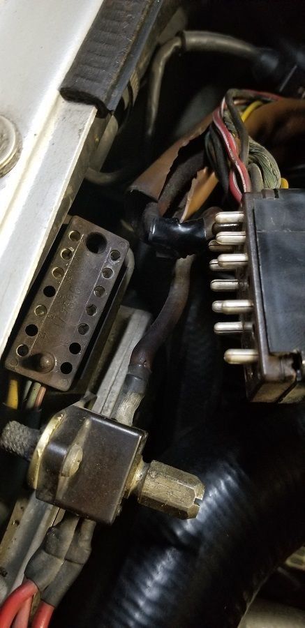
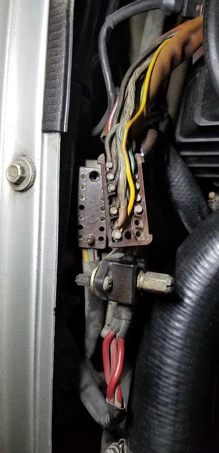
" All that said, did you find that the wire changed colors further up the harness from the connector?" It did not change color. I did manage to first separate the male /female parts of the 14 p/con and then I was able to pry the top cover off. I scraped the brown crud from the 4mm wire cover and it now looked tan. As Mrmarlin points out, it was originally yellow. So now I could look at the multitude of 14 p/con connector diagrams and figure out which one it was (I think)
Here are some pictures. The actual pins look pretty clean:
The picture is looking clearer for me now. I can now run a temporary wire to the starter to make it work. I need to seriously contemplate whether to spring for a new harness or try to make it myself. In addition to the Astro crimper, I have a new, in the box Portasol 125 kit I had also bought for this project. It would give me a great deal of satisfaction to be able to do it myself but I need to find out if it is feasible, in terms of obtaining the proper parts. Will have to investigate that.
I still have not been able to find an electrical schematic that shows where all the wires lead to from the 14 pin connector. There's a lot of that for the newer, '84 and up cars but not for the OBs.
Thank you all who have contributed to my queries. My quest for the redemption of this shark moves on!
Mario
One saving grace of these older wiring connectors, you can easily push the terminal out, now that you have the back cover off.
Once you have it out, the back of the pin is a nice solder cup and doesn't require much in the way of soldering iron to remove the old wire and prepare it for another wire.
Those connectors are one of the things that I liked when I was working on a MB, and as i am about to start working on a '78, I am glad to hear that the Porsche uses the same style.

 08-24-2018, 04:51 PM