When you click on links to various merchants on this site and make a purchase, this can result in this site earning a commission. Affiliate programs and affiliations include, but are not limited to, the eBay Partner Network.
There are only a few things left to repair on my '83, one of them being the power mirrors. From what I remember the left side mirror moves left/right only and the right mirror moves left/right/down. I would like to be able to test both the motors and the wiring to track down the problem.
I am trying to make sense of the wiring diagram to learn how it all works electrically and this is what I have so far. If this helps anyone else then all the better.
I have already tried applying every combination of power and ground between any 2 pins of the 6 pins at the motor and got nothing so it is a bit more complicated than that and I am missing something.
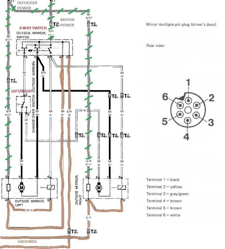
One set of gray/green stripe wires come from the F2 terminal at the CE panel which originates from the defogger relay terminal �87�. They are paired, one wire to each mirror. The other gray/green stripe wire comes from F1 which simply originates at fuse #9 and goes into the 4 way (up/down, left/right) mirror switch. I have colored the grounds brown and note that the terminals on the devices are numbered.
My thinking is that with the left/right mirror switch in the left position (as it is drawn in the diagram), if I try to move the mirror towards left then power would flow out terminal 3 of the 4 way switch, through the left/right switch and into terminal 2 (the mirror motor). The wire between term. 1 at the mirror and term 5 at the switch would be the ground. To move the mirror towards the right the roles of these two wires would be reversed.
Where I am lost is how the up/down movement is accomplished but I am guessing that power flows from term. 6 of the 4 way switch to term. 6 at the mirror and an actuator of some sort changes the axis of motion.
Based on this logic I would think I have to apply power to pin 2 and ground pin 1 but I have tried that and got no movement so I am wrong. For an up/down test I would apply power to pin 2 & 6 and ground pin 1 & 5. To test the heating element would be power on pin 3 and ground pin 4.
I have tried to be as clear as possible and hope this makes some sense.
You're correct that the left right switch sends power to either the left or right mirrors. The 4 way switch then drives the motor forward or backward. The same 4 way switch also energises a solenoid in both mrirors if necessary to change the plane of the mirror. I think up/down energises the solenoid and left/right doesnt from memory. So basically a single motor can move the mirror in 4 directions.
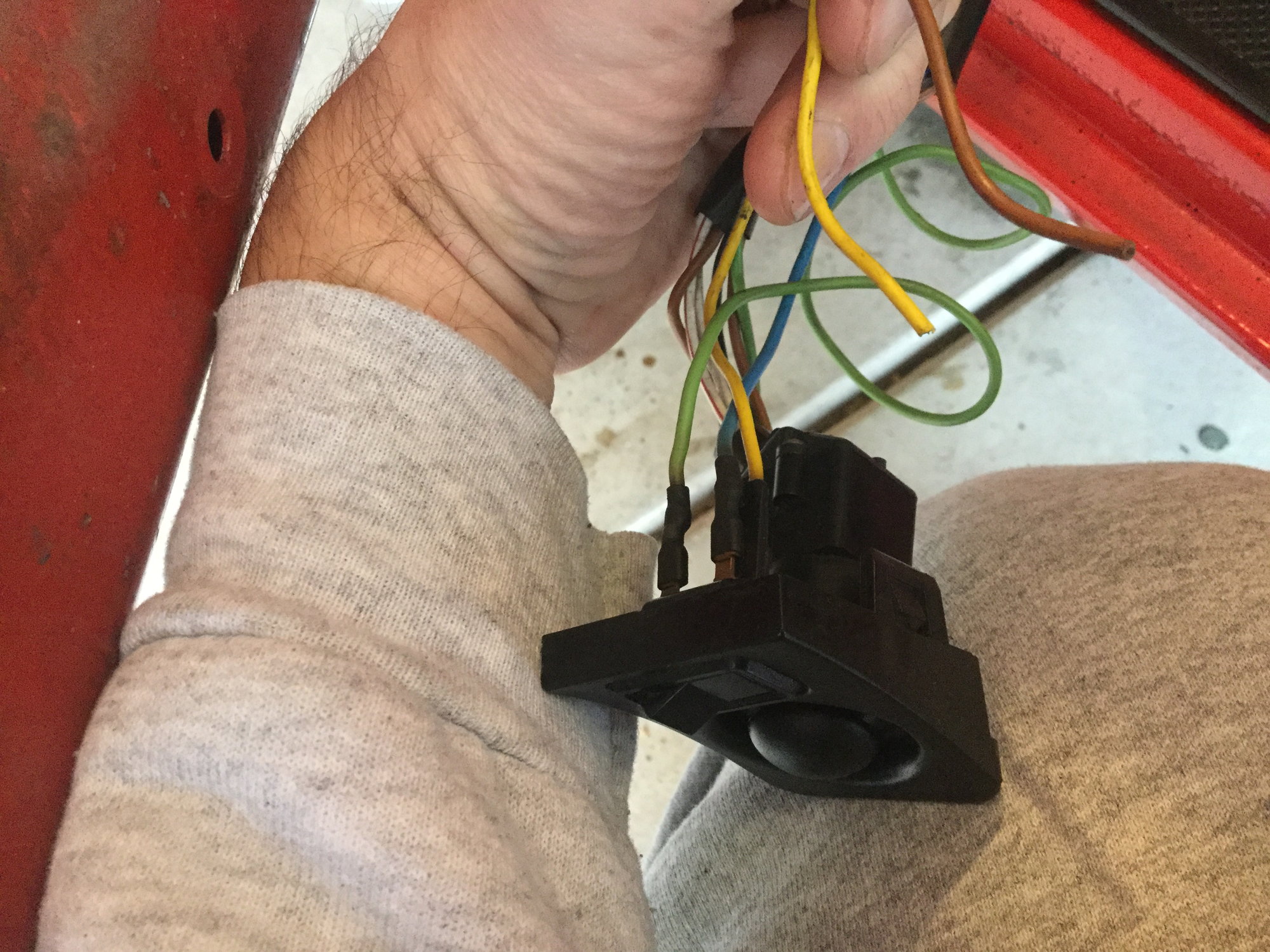
The struggle is real. I’ve found a mess in my door, no power mirrors, cut wires and no sign of where they should go or reason they were cut.
Yellow and brown wires coming from switch have been cut.
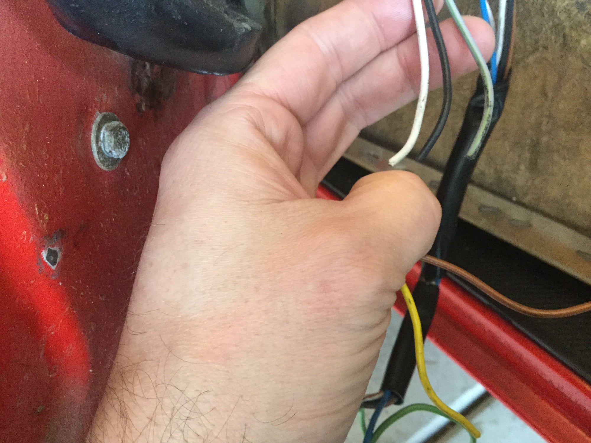
Black white and gray with a green stripe have been cut.
I had a chance to tinker some more. I must have mis-remembered because my right mirror works in all four directions but the left does not at all, though the motor clicks for up and down. I think the relay and switches are OK then. I figured out why I cannot power the mirrors with jumper leads - they only deliver a little over 6 volts even connected to the car battery. My wires are too small.
I get weird results when testing for potential at the mirror plug.
12v bet. pin 5-6 in the up AND down direction, no polarity reversal.
12v bet. pin 1-5 for down and right
12v bet. pin 2-5 for right only.
Nothing for left.
I should test the working right mirror but I think the problem lies in the wiring in the door between the switch and mirror. Since the left mirror is easy to adjust by hand I think I am going to leave it for now until the next time I have the door card off.
Sorry the above won't be helpful but I am putting this down so I can pick up where I left off in the future.
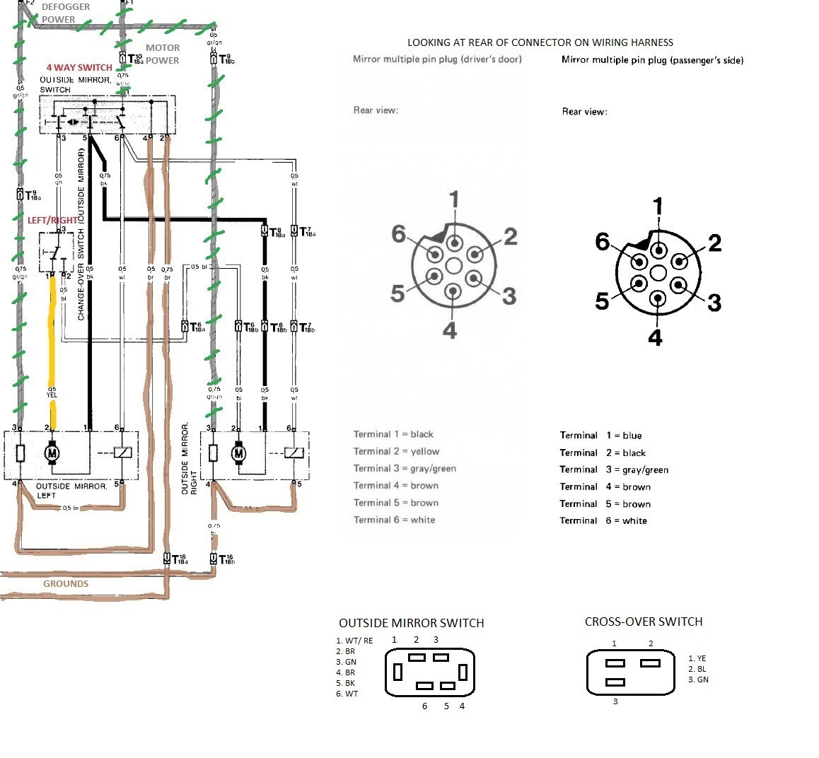
Picking up where I left off, I got both mirrors and heat working. I'm still not exactly sure how a mirror could be bench tested but I figured out the wiring. For one thing, my left mirror must have been ripped off because all the parts are stamped '86 and the wire harness had been cut and twisted together. I soldered the connections and then puzzled over the wiring diagram and WSM. Through trial and error I got everything working 100%. My main problem was the cross-over switch wired incorrectly.
There is an error in the wiring diagrams showing a black wire from the cross-over switch to the left mirror that should be yellow. This is shown correctly in the manual's mirror plug schematic. This illustration may be helpful.
By the way Wohlmeyer, your cross-over switch is wrong

 03-18-2018, 10:03 AM