When you click on links to various merchants on this site and make a purchase, this can result in this site earning a commission. Affiliate programs and affiliations include, but are not limited to, the eBay Partner Network.
For checking for/finding intake leaks, find a copy of Dwayne's guide for the "intake refresh" project. He shows how to make a fixture from plastic waste pipe and fittings, commonly available stuff at home centers in the US. The engine is rotated to 1TDC minus 45�, the same spot where you fit timing belts, so that valves are closed. Then a little compressed air is added, and you listen for where the air is coming out.
Have you had a look at the condition of the wiring harness just before and entering the MAF [i.e. under the boot]? You need to eliminate this as a problem just as you have other possibilities.
Once the items outside the inlet manifold have been eliminated it will then confirm what some of us suspect to be causing the issue- my money is currently on a split in the pipes around the ISV simply because the problem is around idle to 2k. lf original fitment they most definitely need replacing as will the knock sensors and the CPS/Hall trigger even if they are working at the moment.
You said the ignition leads, distributor caps and rotor arms have been replaced but have the fuel pressure controller and dampers been replaced at some stage previously? Whereas the smell of fuel in the vac connection is a performance indicator for failure, if those items are still the originally supplied ones, one wonders whether they can possibly be working as intended.
Rgds
Fred
Fred: thanks for your follow up.
- I will be checking upon the MAF wiring harness as my next task and report here, as part of my current ongoing elimination list.
- As part of my upcoming intake refresh, I will change the current still working fine knock sensors and the CPS/Hall sensors - as good WYAIT preventive maintenance.
- And as also my fuel pressure controller and dampers are still the original ones, those I will replace as well during my upcoming intake refresh.
Originally Posted by SeanR
Double check the rotors internally if you haven't yet. Had this on an '88. While the car still ran fine it had a stumble. That is ran as well as it did is amazing.
Main coil node is missing.
Pano's had one like this.
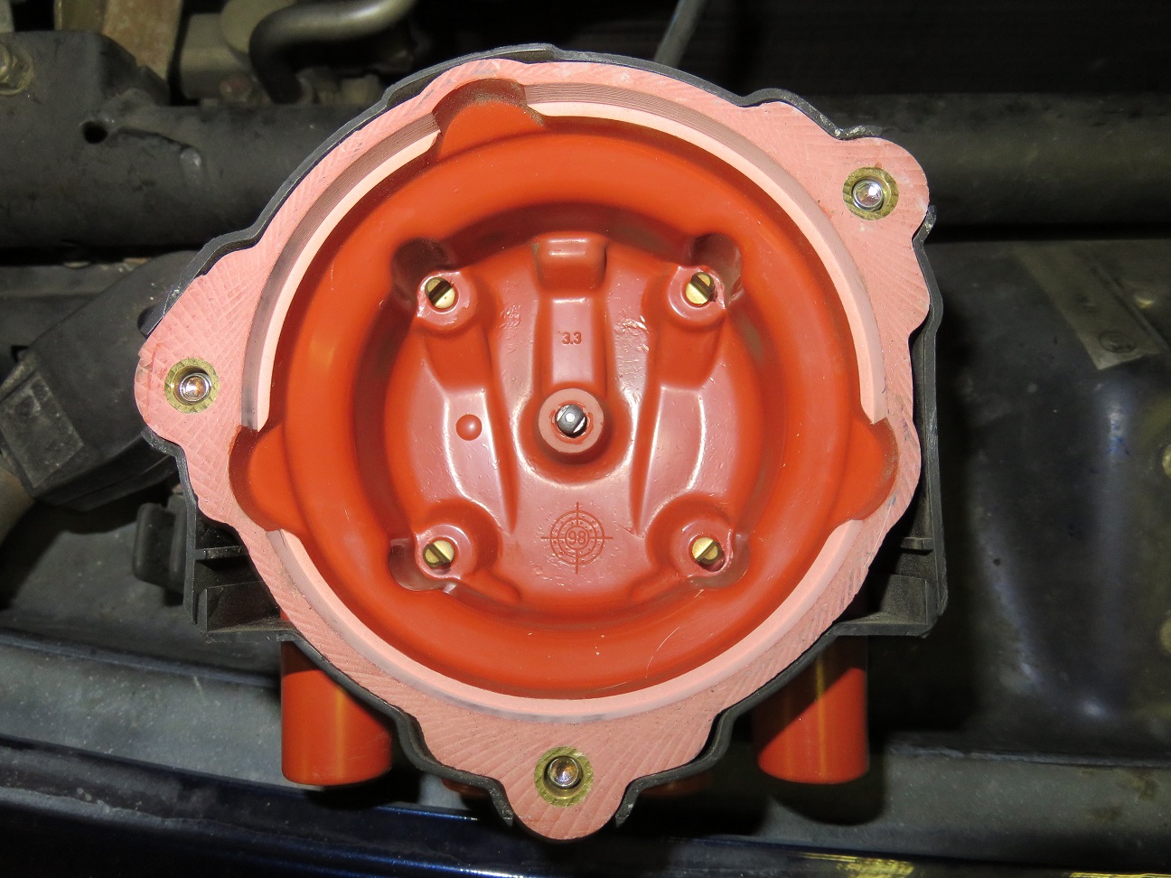
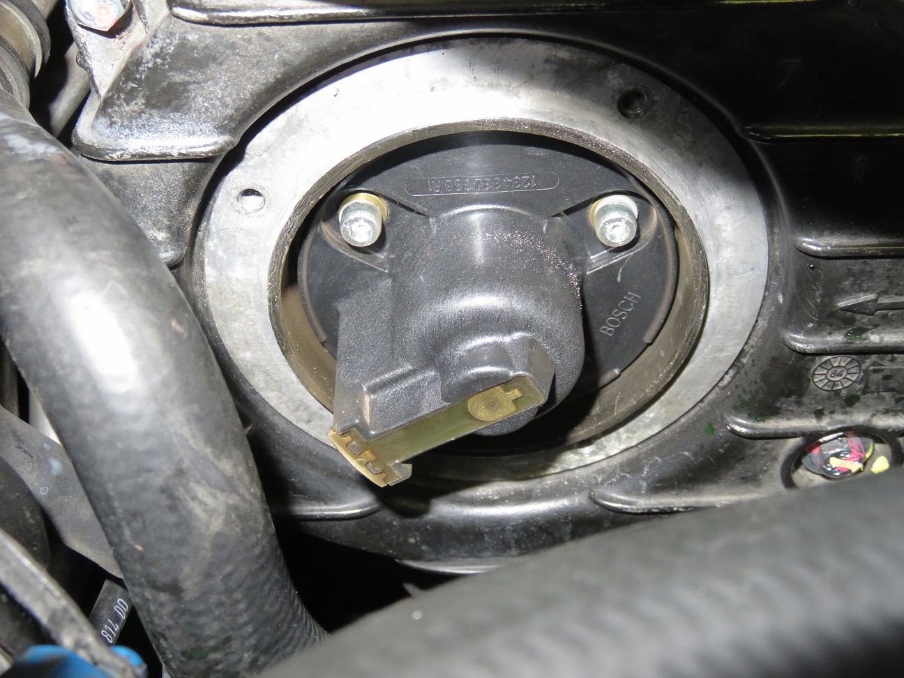
Sean: thank you for having shown this as a possible fault condition for this type of problem to us all. Checked mine therefore this (my local time in Finland) evening, both look fine though:
Passenger side, inside of the distributor cap:
Passenger side rotor:
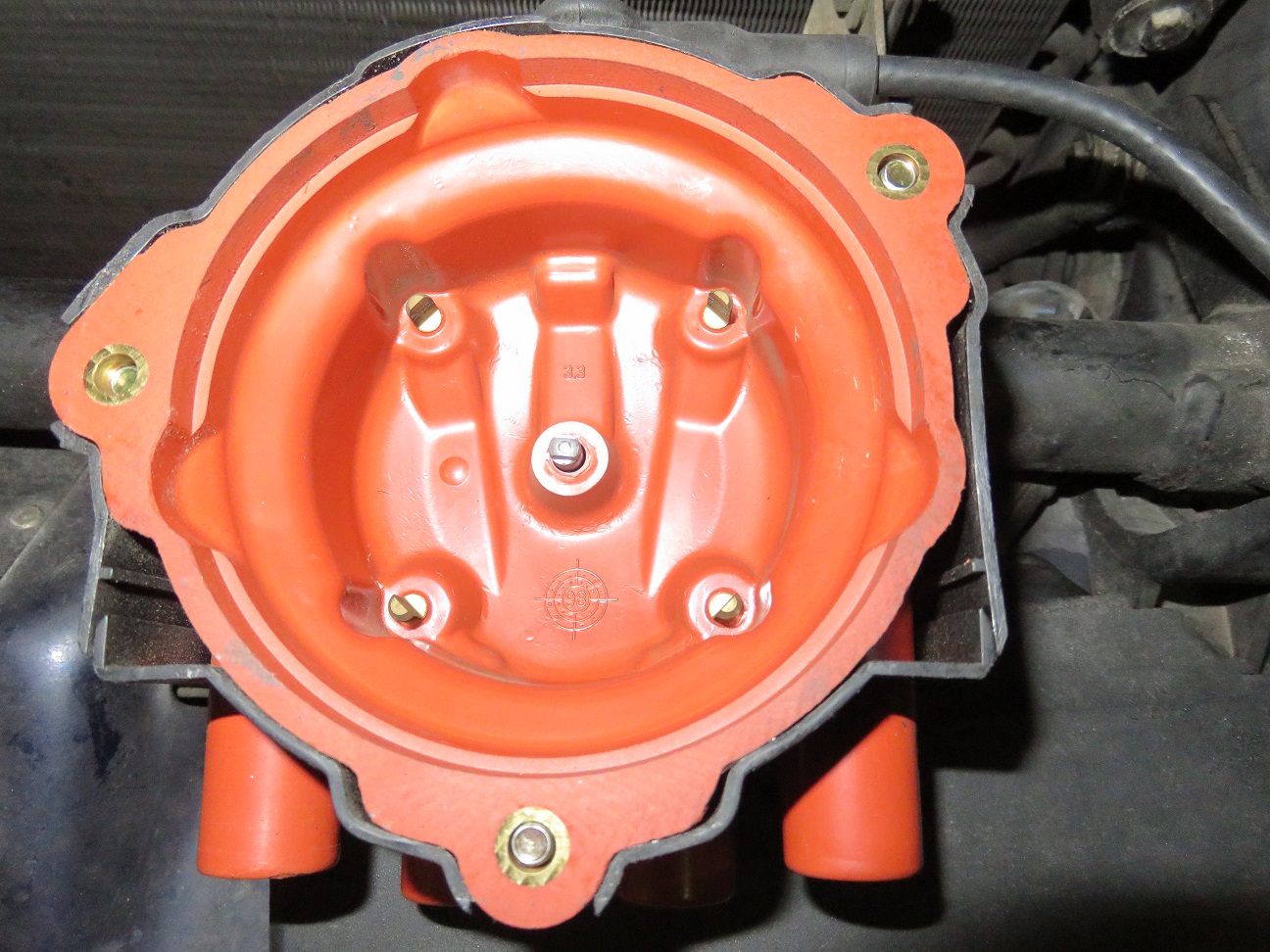
Drivers side, inside of the distributor cap:
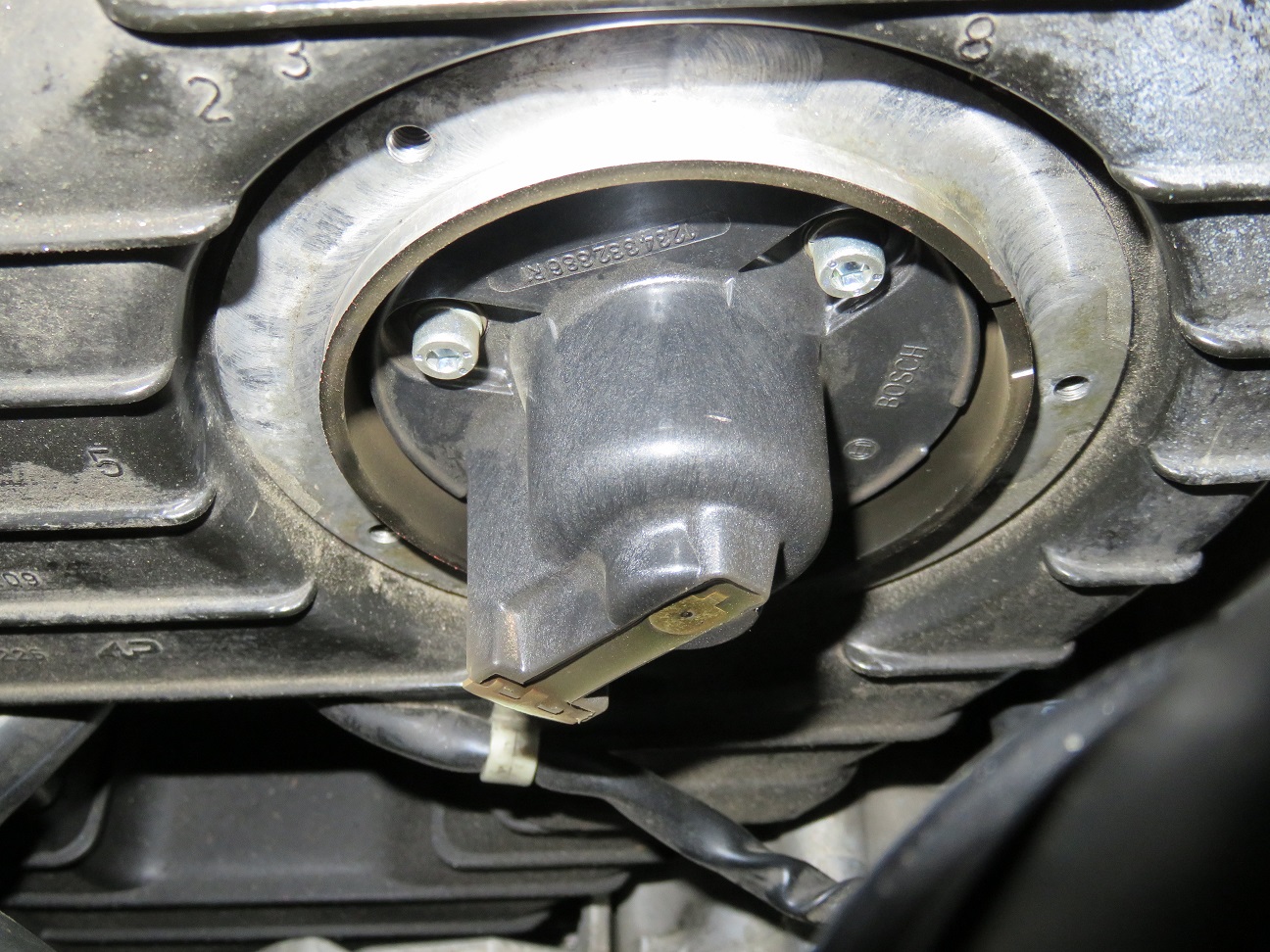
Drivers side rotor:
Originally Posted by dr bob
For checking for/finding intake leaks, find a copy of Dwayne's guide for the "intake refresh" project. He shows how to make a fixture from plastic waste pipe and fittings, commonly available stuff at home centers in the US. The engine is rotated to 1TDC minus 45�, the same spot where you fit timing belts, so that valves are closed. Then a little compressed air is added, and you listen for where the air is coming out.
Dr. Bob: where would I/we be, without Dwayne's excellent guides? So yes: already had his (re)looked up for this, as per link: http://dwaynesgarage.norcal928.org/1...%20Refresh.htm and I will follow it as dilligently as I can.
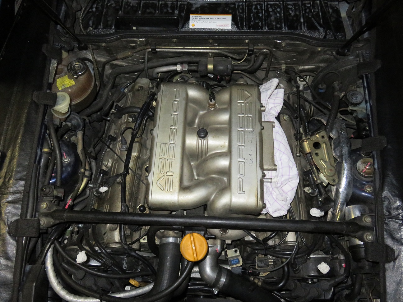
Time flies...one month later and with parts ordered & very quickly delivered (thanks Roger!), here is where I am now with my ongoing intake refresh (as nothing has ever been touch there, since coming out of the factory in 1994).
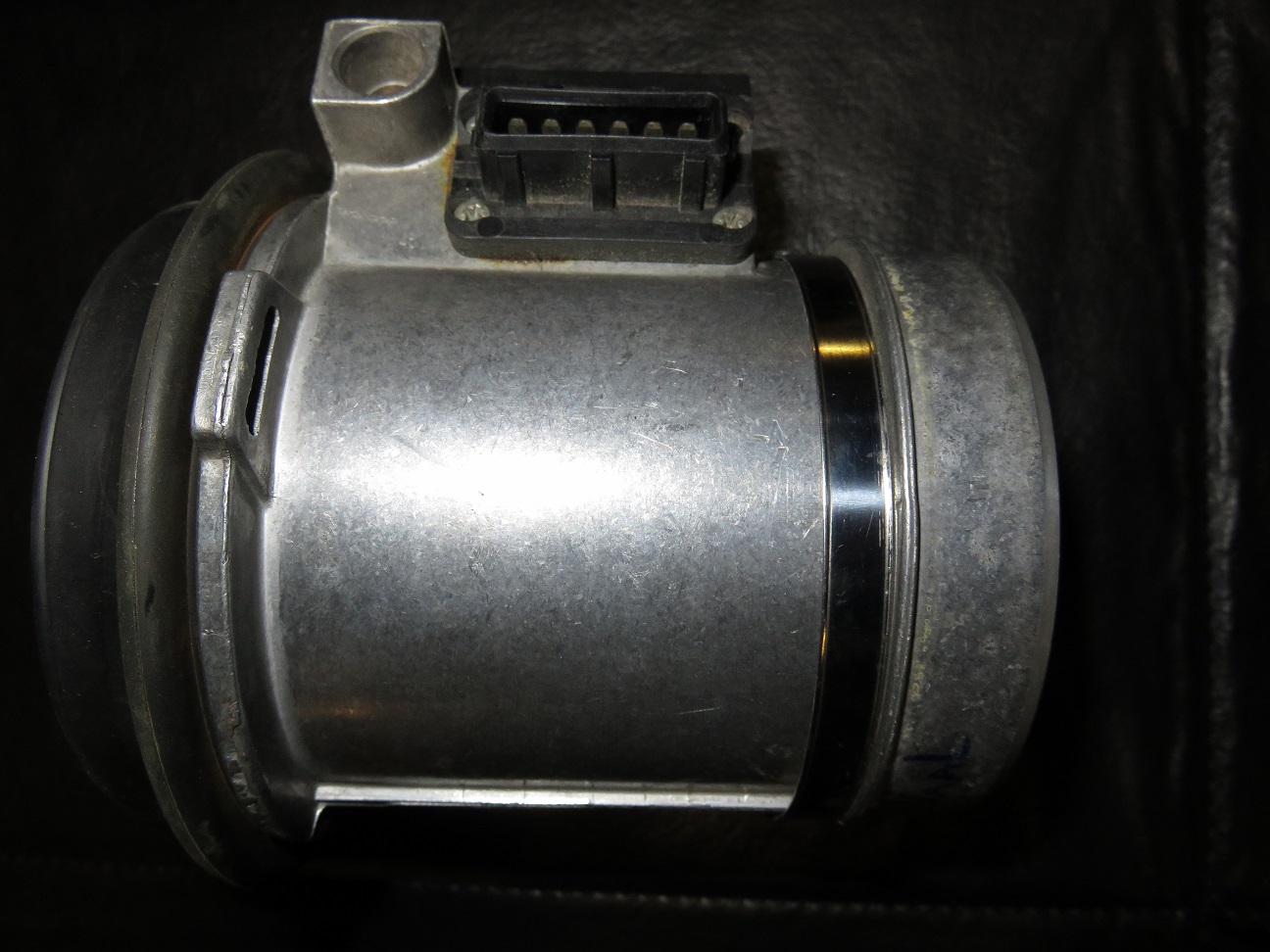
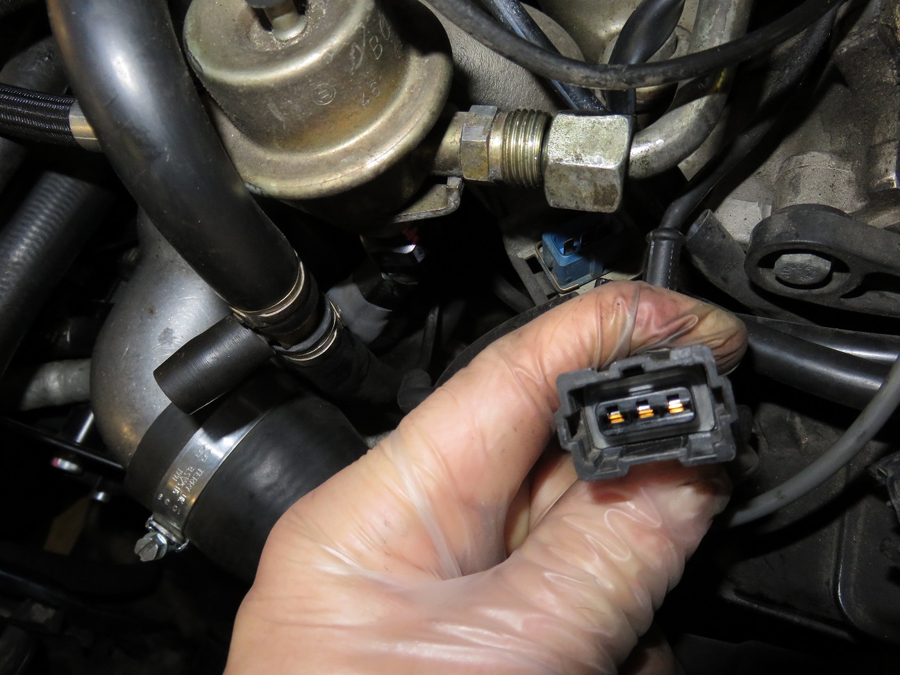
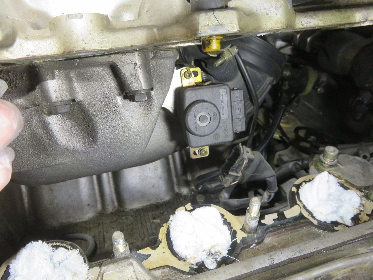
MAF removed, and visiually checked all to be as fine as when I received it back all recalibrated from John Speake in 2013. MAF connector (and also the car MAP connector harnass) all looking very fine:
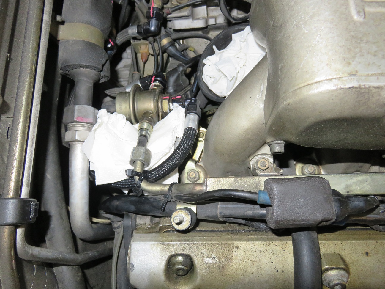
Back of the V knock sensor connector is actually neatly wrapped up, as can be seen here on top of the passenger side fuel rail:
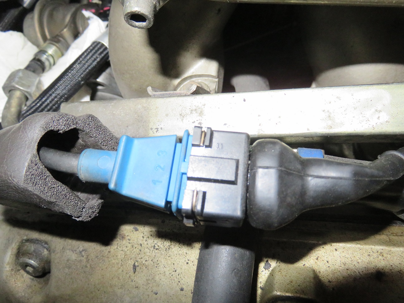
Despite many heat cycles in the engine bay, the knock sensor connectors look to still be in very good shape (and yes: I will replace the knock sensor regardless):
And the same for the front of the V knock sensor connector, all in very good shape too (and yes: I will replace this knock sensor regardless as well):
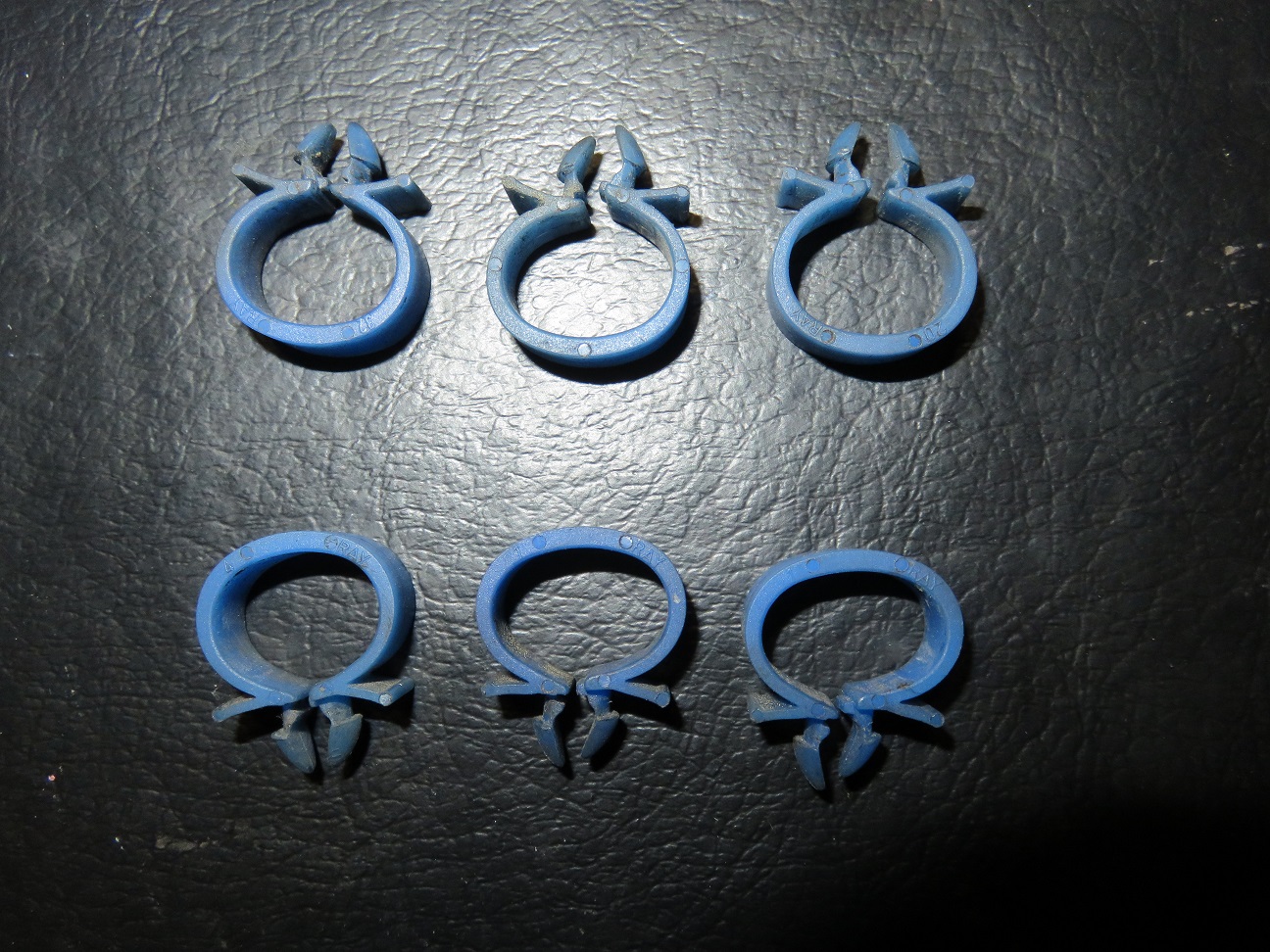
All six blue fuel rails harness clips came of unharmed, and are in good shape (I will re-use these):
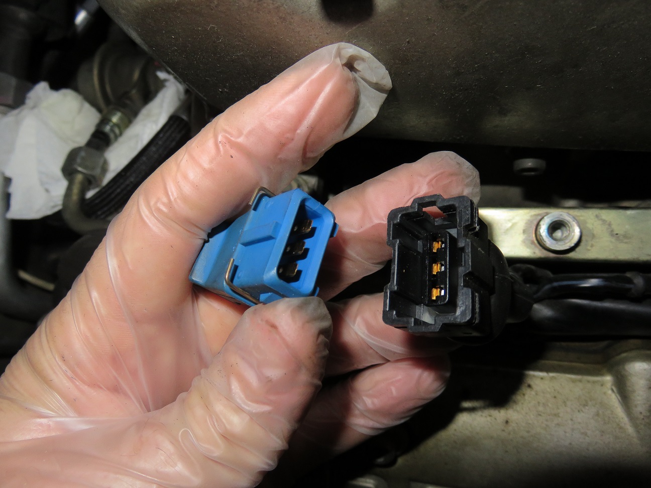
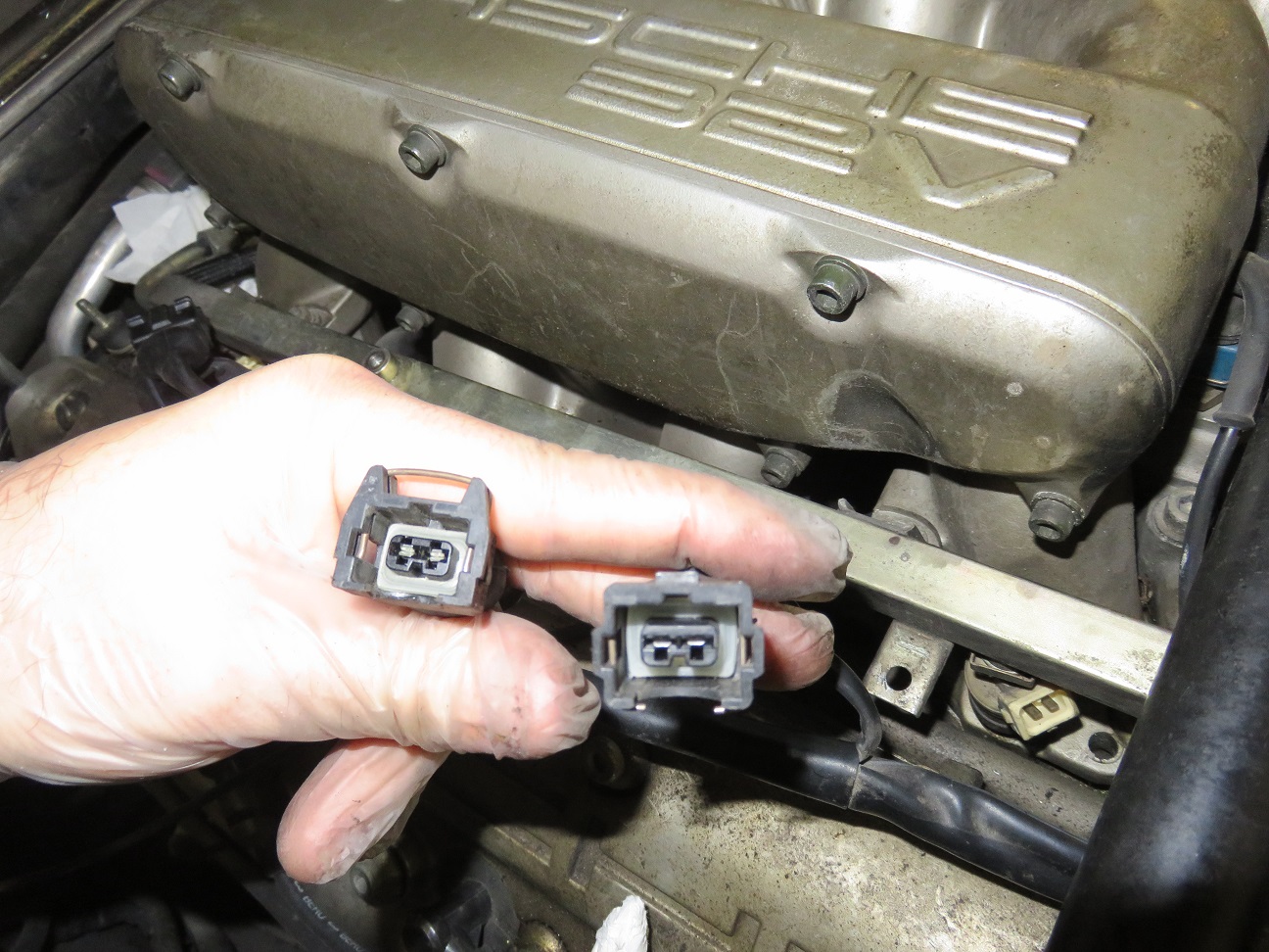
One interesting find: the injector harness for cylinder 1 - as can be seen here on the right hand side - is slightly different when compared with cylinders 2 - 8 (which are all similar) - which can be seen here on the left hand side.
The cylinder 1 harness metal clip had to be pushed out a bit with the help of screwdriver and only then could get "wiggled out" from the injector, while on all others it was super simple by just having to push the metal clip in by hand.
I wonder if this is a normal harness for MY1994, or is it just always a mishmash of whatever connectors Hans & Frans had in the factory?
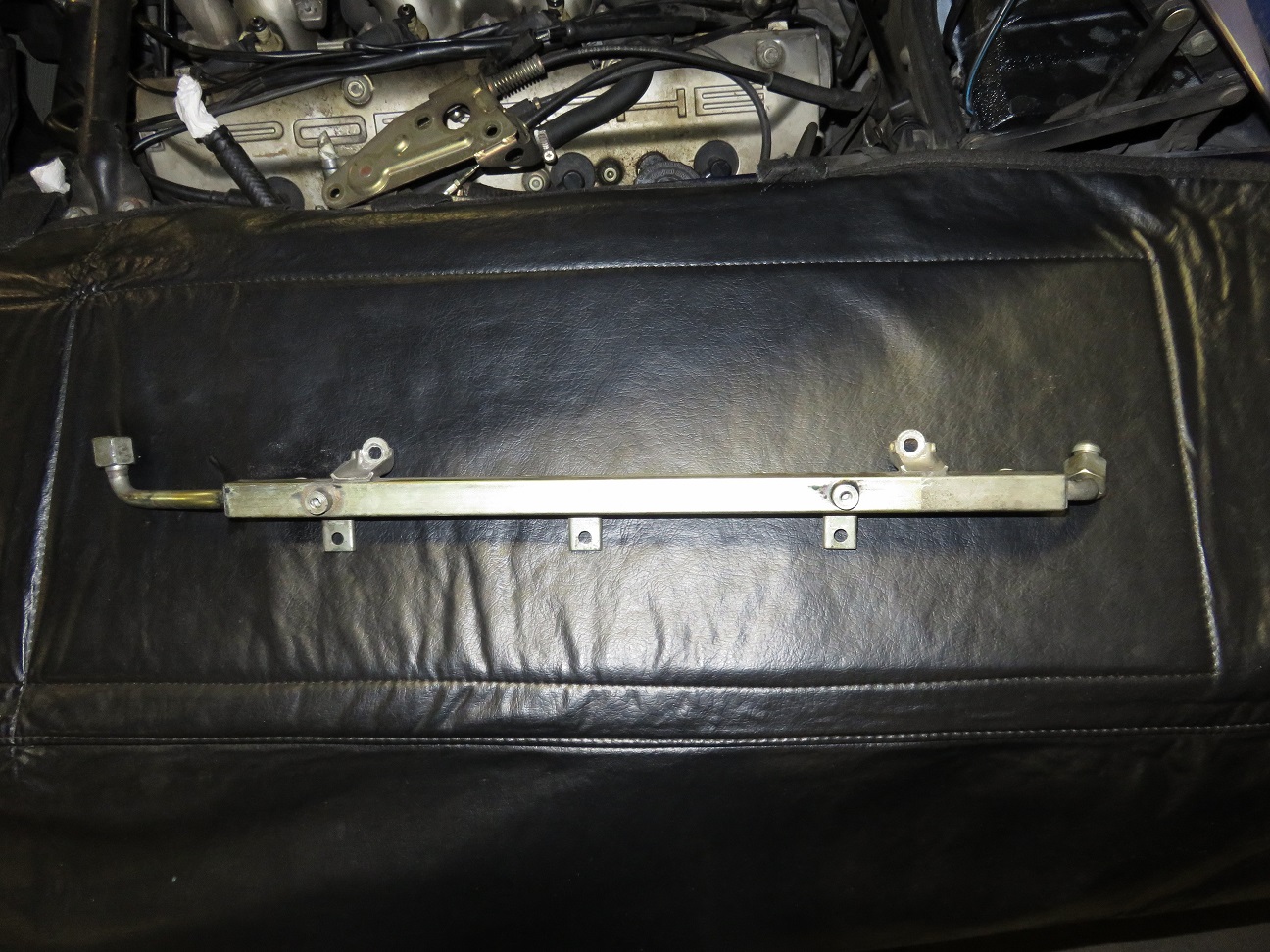
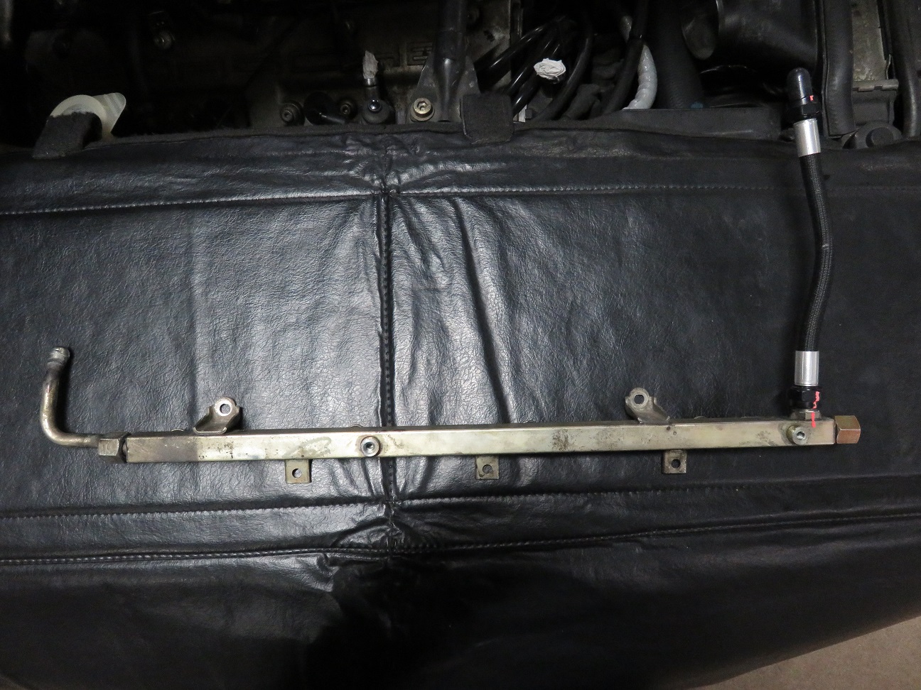
Driver side fuel rail removed:
Passenger side fuel rail removed:
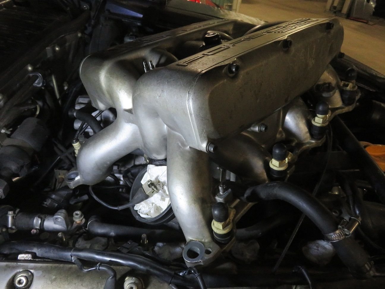
Current status (next: taking out the injectors, etc. etc.):
I have had similar symptoms on a 964 which turned out to be a sticky MAF. But yours has been serviced. Still worth swapping with another one to rule out a fault.
Quick question the vacuum line at the V in 32 V is Connected to where? Mine is hanging loose.
Thanks as this has been bugging me for a while. Car seems to run fine.
Im thinking hose as well..........I had the under intake hose from the ISV to throttle body split and cause idle to partial throttle issues; hose was new as Sean described.
I have had similar symptoms on a 964 which turned out to be a sticky MAF. But yours has been serviced. Still worth swapping with another one to rule out a fault.
Quick question the vacuum line at the V in 32 V is Connected to where? Mine is hanging loose.
Thanks as this has been bugging me for a while. Car seems to run fine.
Charles:
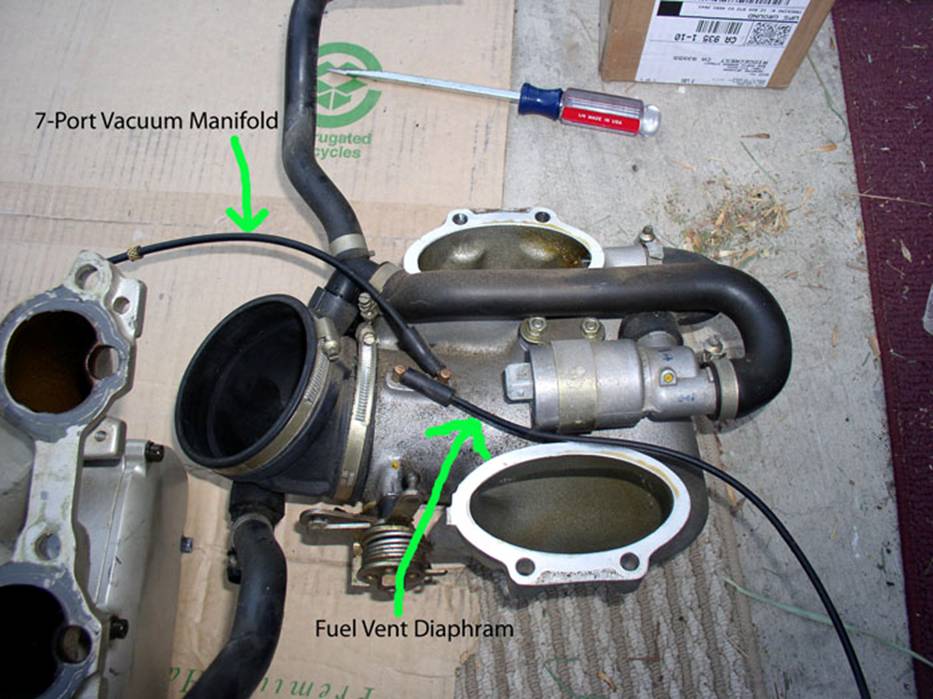
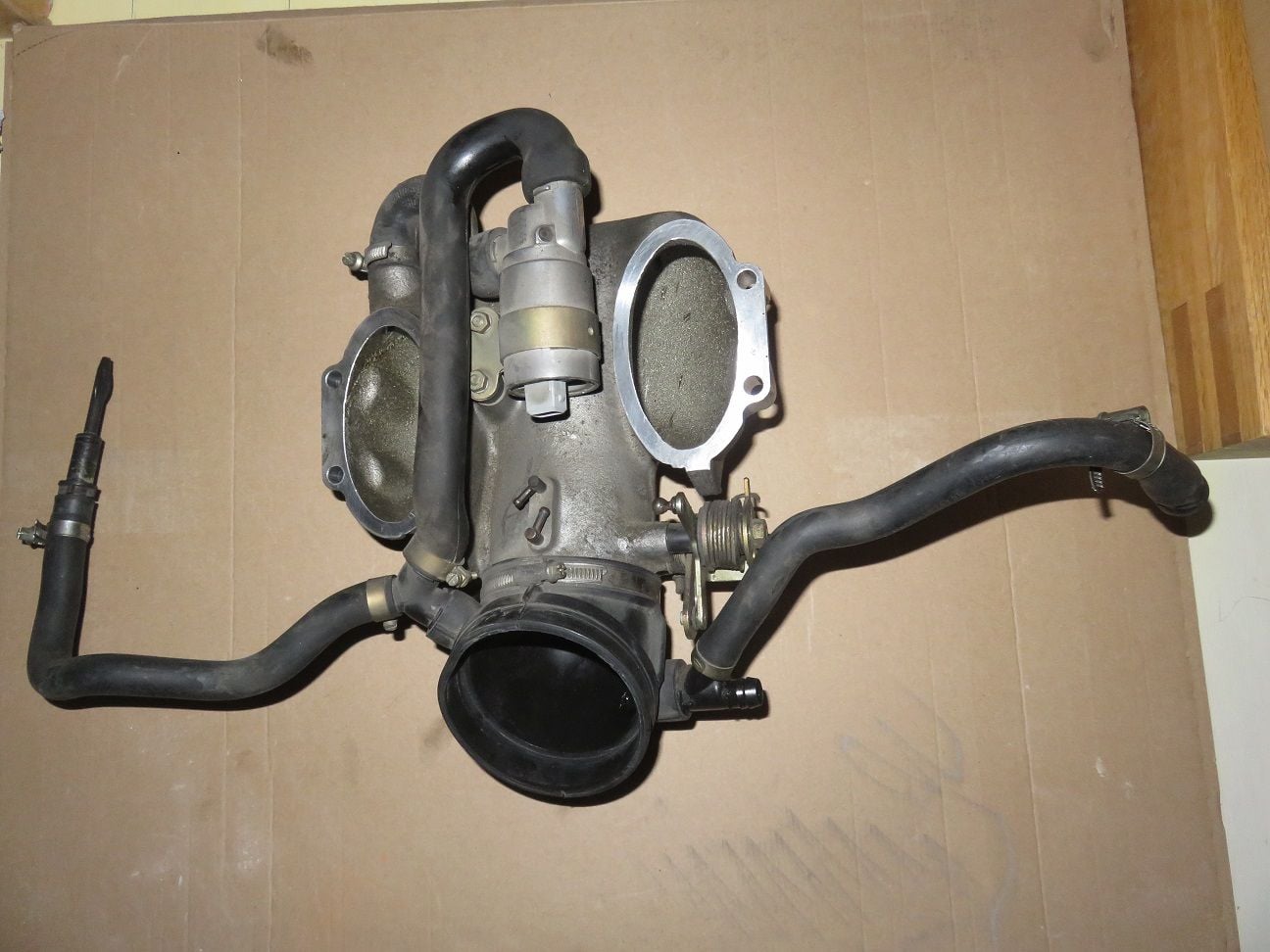
The vacuum line at the V in 32 V (on the passenger side) is connected from the fuel tank vent diaphragm that resides next to the coolant reservoir, to the throttle boddy.
See the following clear photo + text to explain the "where" on the throttle body, as I have taken/borrowed from Dwayne's excellent Intake Refresh write-up: http://dwaynesgarage.norcal928.org/1...%20Refresh.htm
" There are two vacuum lines attached to the throttle body. The shorter line coming out the left goes to the 7-way vacuum manifold while the longer line goes to the fuel vent diaphragm that is located next to the coolant reservoir. "
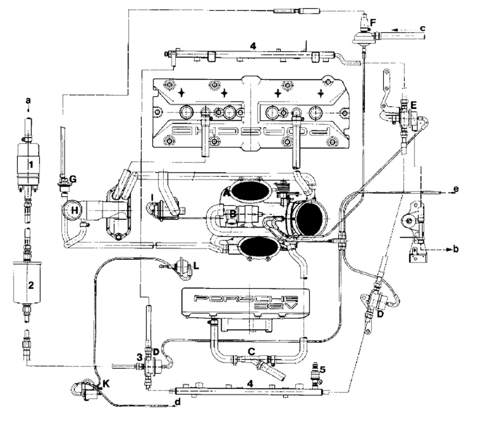
And hereby the S4 + GT + GTS vacuum diagram picture (post edited: as can be found from Work Shop Manual 1A, chapter 24 page 216):
Post-edited: explanations of the various numbers + letters in above diagram, as per Work Shop Manual 1A, chapter 24 page 217:
A - Throttle housing
B - Idle speed actuator
C - Intake jet pump
D - Pressure damper
E - Pressure regulator
F - Vacuum valve
G - Electric tank breather valve
H - Oil filler neck
I - Secondary-air valve
K - Vacuum-operated switch valve (tune-intake flap)
L - Vacuum unit (tune-intake flap)
a - from fuel tank
b - to fuel tank
c - from activated charcoal cannister
d - from vacuum reservoir
e - to automatic transmission
Originally Posted by the flyin' scotsman
Im thinking hose as well..........I had the under intake hose from the ISV to throttle body split and cause idle to partial throttle issues; hose was new as Sean described.
good luck
Malcom: thanks for your input and findings from your car, when you had that happens. This seems to be most common problem then, and purely age induced - as even the youngest 928's are now 22+ years old.
As I am - very slowly but surely - getting closer and closer to finding and fixing my root cause, I will keep this threat updated for all until fully "done".
Last edited by Arnoud; 09-15-2017 at 08:43 AM.
Reason: Some post-editing, so to add the relevant WSM pages/information into it.
Arnoud - that diagram isn't valid for the GTS wrt PCV, the vacuum side may be OK..
e.g. It doesn't show the front head to head balance tube and has too many connections to the oil filler.
Alan
Alan: you are correct, thanks for having pointed this out.
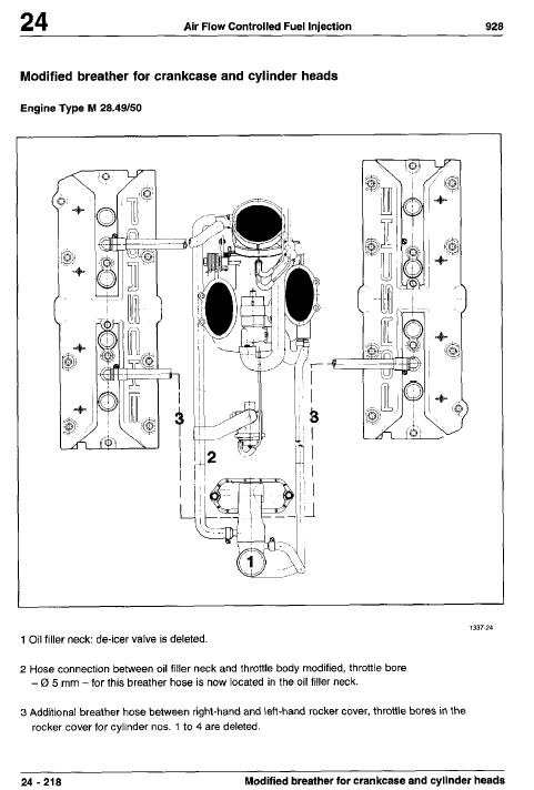
For the GTS, there is additional information on items like the head balance tube - as per Work Shop Manual 1A, chapter 24 page 218. Added here for completeness of this threat (and I also updated a bit more info on my previous post #21):
Don't you hate threads that start of well, and then suddenly stop and you do not find out what happened next nor the root cause of the reported problem? Me too!
I had another classic spell of "the best-laid plans of mice and men..." happening, i.e. that thing called life. So all has been on hold until some weeks ago, yep: 7+ months later after my previous post. So what has happened during the past few weeks with this? Good, and some not so good things...info to come in the next posts.
The TPS connector is very easily removed, when the intake is tilted/raised 10+ cm's:
The ISV connector was easy just to wiggle of by hand, once the intake had been turned diagonally:
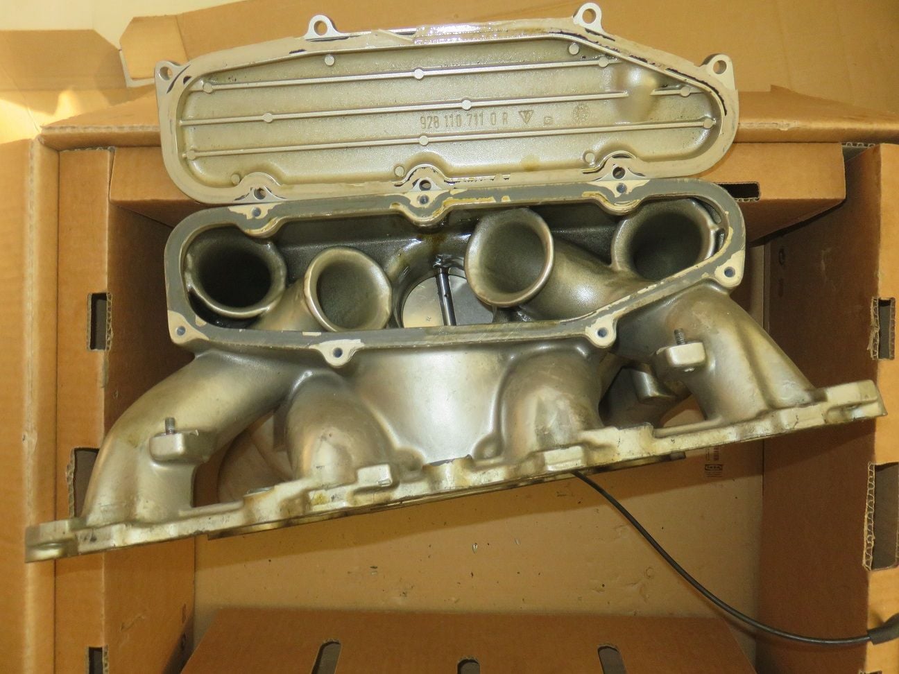
State of the V: not to bad actually after 24 years:
Separating the throttle body from the intake: lots of oil everywhere...as all have reported before:
And no clamps from the factory on my ISV. But: no split hoses anywhere, so that is NOT the root cause of my problem...
Anything rubber I am renewing, as well as the ISV + TPS + vacuum diaphragms. A few of the many new rubber bits to begin with:
Yep: oil everywhere...
Baselining the old TPS (the MY 1994 + 1995 have 6 connections) before it's removal + measurements of it:
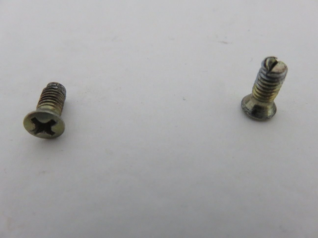
New sharp bit, and using the lowest torque setting on a small manual drill to get the throttle plate Philips screws out - as Captain_Slow/Jon mentioned in his intake thread (thanks Jon for this tip!). Worked very well for me too.
The throttle plate screws in question, as removed:
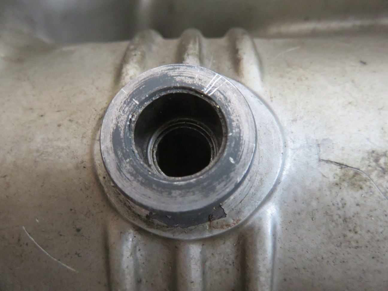
The procedure for the needle bearings removal is the same for all four (4) of them: start with taking the seal out. From the factory they are only single sealed:
By taking the seal out, it creates the necessary room so to remove the needle bearings and it's cage:
And unless you have one of those very nice slide-hammer kits with the little collets, like Sean and other professionals have, another excellent needle bearing removal tool is a small sized bicycle bearing puller that can go inside 10mm openings. Showing successful action here, on the intake bottom flappy needle bearing:
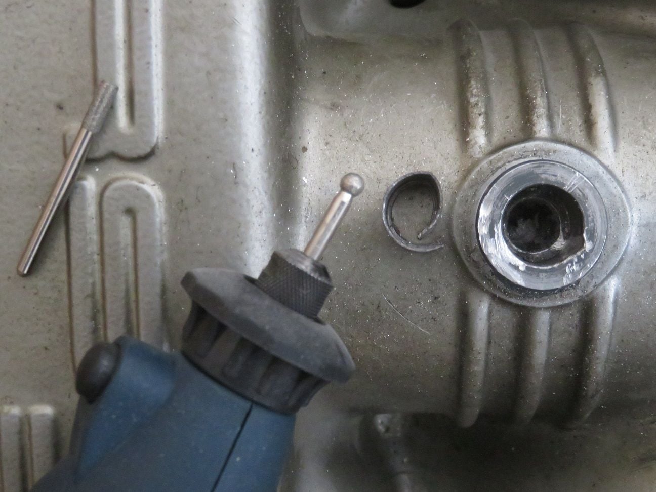
BUT: problems are always possible..." Oeps " moment here, when on the top flappy needle bearing I did not put all 3 legs of the bearing puller properly inside it, and then the top bended part of the needle bearing shell broke off...Oeps indeed...
To get that removed, I had to now do exactly what I had wanted to avoid at all costs: using a dremmel like tool to cut through the bearing shell, which then of course will also make a cut into the wall (and thereby creating a possible vacuum leak path). As there was no shop around that sold a tungsten carbide cutting bit/drill, I ended up using a diamond coated cylinder + ball drill bits - which did the job in less than one minute:
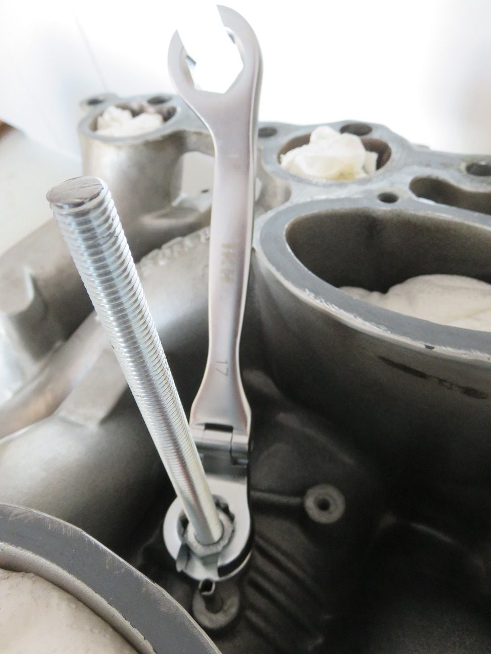
Then followed by using Dwayne's documented method to get the new double sealed needle bearings back into their housing. Do NOT push the 10mm rod through the new bearing, because that will rupture the new seals! Just carefully rotate it in (which takes a bit longer, but who cares about a minute more so to keep the seals in tact?):
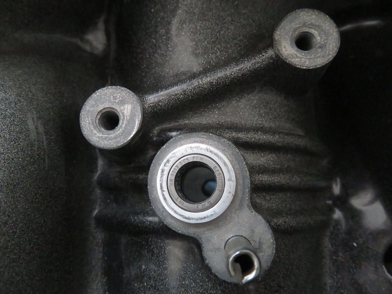
The new double sealed needle bearings on the intake for the flappy, go in with the flat side on the outside:
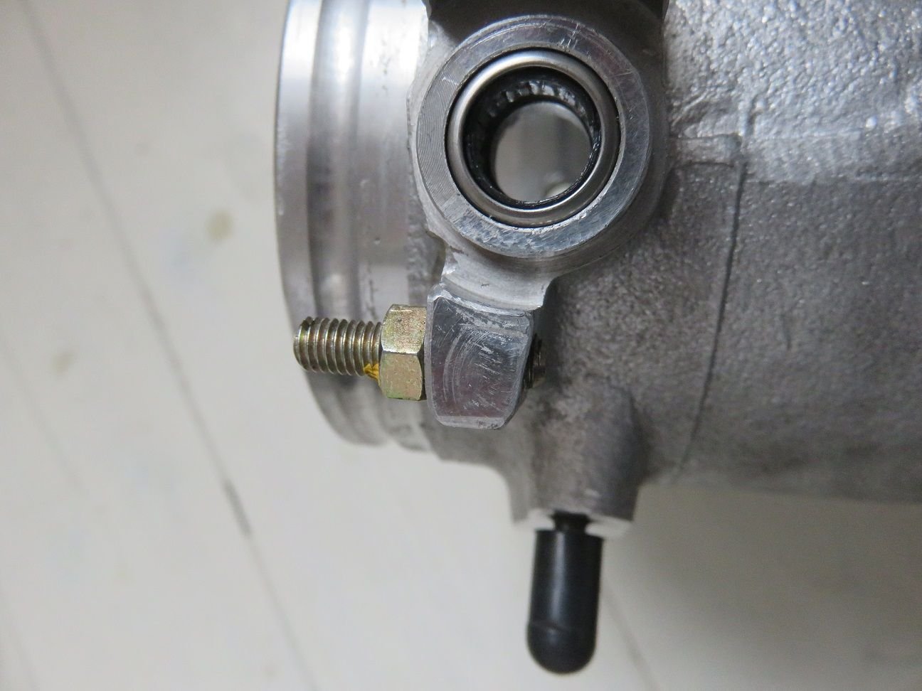
While on the throttle body, the new double sealed needle bearings go in with the bowed side on the outside:
Nice that your getting back to your project,
are you planning on powder coating the intake ?
If so you would want to install the flappy bearings after its been PCd and cleaned
Nice that your getting back to your project,
are you planning on powder coating the intake ?
If so you would want to install the flappy bearings after its been PCd and cleaned
Hi Stan,
Good question and thanks for you correct made comment: I will not do any powder coating of the intake or other parts, as I currently do not want to have any of the possibly additional headaches coming from powder coating it. So this is a very consciously made decision by me, as you will find out in posts still to come that I had to battle a few more other " oeps..." problems in the meantime. I might paint it "in situ", once it is fully back in place and all working fine. For the moment however, I am fine with it showing it's "life patina".
OK, thanks for the further info.
I would suggest that you take the side plenums and have them blasted to clean out the sealing grooves,
as they are now ,where the PC thats come off will not give a smooth sealing surface.
use a razor blade on the intake portion.
Carry on and post more pictures
OK, thanks for the further info.
I would suggest that you take the side plenums and have them blasted to clean out the sealing grooves,
as they are now ,where the PC thats come off will not give a smooth sealing surface.
use a razor blade on the intake portion.
Carry on and post more pictures
Thanks for the follow up advice, and that's exactly what I have done. More pictures coming up...


 07-22-2017, 08:20 PM