NO SPARK!!! This car hates me!!
 07-25-2003, 10:10 PM
#46
Addict
Rennlist Member
Rennlist Member
Originally posted by 89magic98
Just make sure that the shim will not come off inside the bell housing while doing this. The factory manual suggests taking an old sensor (which Dan has, because he said he has two brand-new ones in the car) and crazy-gluing a .8mm shim to it, and making it a permanent measurement tool.
-Kevin
Just make sure that the shim will not come off inside the bell housing while doing this. The factory manual suggests taking an old sensor (which Dan has, because he said he has two brand-new ones in the car) and crazy-gluing a .8mm shim to it, and making it a permanent measurement tool.
-Kevin
I did mine with the motor out of the car, so of course, it was a lot easier.
Since you have a scope, I'd go that direction. As Danno said, a 2V pulse should be seen. IIRC there are 3 triggers on the flywheel, so look for 3 pulses per revolution.
That really is a crappy setup... but as long as the triggers have not been moved from the factory settings, aligning the speed sensor with the ring gear aligns the reference sensor. At least they made it somewhat simple.
Hang in there Dan!!! I'll check the list tomorrow to see how things are going. Wish I had the weekend off.. I'd make the drive to come and help you.
 07-25-2003, 10:42 PM
#47
Burning Brakes

Originally posted by Tom Carson
a bad ignition switch will screw up the +12 V to the coil
rig a wire from the + battery terminal to the ignition coil's thin black wire of the ignition coil...(not the green...that's where the plusing ground from the DME goes to)
also a failed FPR (they fail 'high') can cause the injector circuit of the DME to 'load down' and not supply the proper ground pulsing to the injectors and I'm assuming the ignition coil ground pulsing as well...so no spark??
pull a injector plug to see if it runs on 3 of the 4
report back...
07-25-2003, 11:08 PM
#48
Nordschleife Master
Thread Starter
Well guys I decided to fix the problem my way, below are some pictures of the step-by-step procedure I did in order to fix the no spark issue. I took pictures just in case someone else had the same problem I did to make it easier for them to fix it as well. 
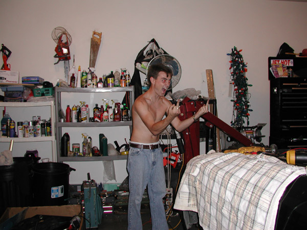
First you need to think about the problem like I did in this photo below. As you can see I'm in a deep trane of thought. Then it hits me on what I need to do!

Once you have thought about the problem and came up with a solution, now is a good time to fix it, like I did in this photo below. Remember aiming is critical. See my form in this picture I hit it dead on! Take that P1 (P1 stands for first Porsche)!!

Now after I have fixed the problem I rejoice and give it the good ol universal salute.
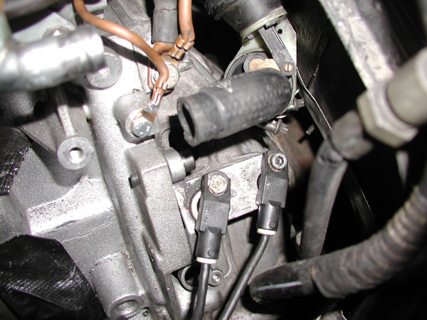
On a more serious note here is a picture of my grounds.
Thanks for the help guys I really appreciate this. Now I know how perry felt when he was rebuilding his!!

First you need to think about the problem like I did in this photo below. As you can see I'm in a deep trane of thought. Then it hits me on what I need to do!
Once you have thought about the problem and came up with a solution, now is a good time to fix it, like I did in this photo below. Remember aiming is critical. See my form in this picture I hit it dead on! Take that P1 (P1 stands for first Porsche)!!
Now after I have fixed the problem I rejoice and give it the good ol universal salute.
On a more serious note here is a picture of my grounds.
Thanks for the help guys I really appreciate this. Now I know how perry felt when he was rebuilding his!!
Last edited by Dan87951; 07-25-2003 at 11:17 PM.
07-26-2003, 01:15 AM
#49

Originally posted by Dan87951
One question though.
The left hand sensor in the picture has a different bolt than the right hand one. The one on the right is a stock bolt (with the allen head).
The inside of the bolt hole on this sensor is metallic. Is that for a reason? Is it to make a chassis ground for the sensor? Or to just strengthen the plastic so it doesn't crack when the bolt is being tightened.
I am afraid that the non allen-head bolt on the left is not making good contact with the metal in the sensor bolt hole. I know that the bolt on the right has a special shape which allows it to grip the metallic top of the bolt hole.
This is really grasping at straws. But it is an idea that popped into my head.
-Kevin
07-26-2003, 01:22 AM
#50
Two other ideas.
1. Measure the resistance between the negative battery post and the end of the battery cable that connects to the engine ground, report back.
2. Jump pin 4 of the 9 pin connector near the firewall to 12 volts. You should hear fuel flowing. Then start the car. This wire (green/black) is the power for the fuel pump. Otherwise, I don't know how to be 100% sure that the fuel pump is running when starting the car (because the engine/starter drowns out the noise of the fuel pump).
-Kevin
07-26-2003, 02:20 AM
#51
Big thirst, Sore Thumbs
Rennlist Member
Napoleon
Rennlist Member
Napoleon

Dan
It is simple. You can easily fix it. Problem is you are at high stress levels. Spark is easy eonugh. Luckily you have a working 951 to work with. You've swapped coils, DME, DME Relay et al.
Chances ar it is either a ground or a reference sensor problem. Adding grounds are easy. Any wire, and any connectors available, just add them, it can't hurt.
For the reference sensors, play back and forth. Killing the working 951 is just as good info as getting the anderson to work. Checking for magnets is harder. I've played with limit switches for a long time, (Hall effect sensors same as here) in your situation it's a little harder. Hook a Multimeter probe into the sensors looking for resistance. A magnet passing should give you a low resistance signal. (try both + and - signals)
07-26-2003, 05:46 AM
#53
Nerd Herder
Rennlist Member
Rennlist Member
I know- I have nothing better to do at 3:30 am. But I've spent the last half-hour reading this and all I can think of it's something so simple it couldnt possibly be overlooked but has.. like a dam ground or something goofy.
Sit back, relax and free your mind- think nice thoughts. Ahh.. let the Good Karma flow around you... then beat the crap out of a piece of wood with a hammer.
Nice pics Dan- I give the same salute to the 944 often!
Best of luck- you'll get it!
Sit back, relax and free your mind- think nice thoughts. Ahh.. let the Good Karma flow around you... then beat the crap out of a piece of wood with a hammer.
Nice pics Dan- I give the same salute to the 944 often!
Best of luck- you'll get it!
07-26-2003, 07:41 AM
#54
Burning Brakes
Originally posted by 89magic98
The inside of the bolt hole on this sensor is metallic. Is that for a reason? Is it to make a chassis ground for the sensor? Or to just strengthen the plastic so it doesn't crack when the bolt is being tightened.-Kevin
The inside of the bolt hole on this sensor is metallic. Is that for a reason? Is it to make a chassis ground for the sensor? Or to just strengthen the plastic so it doesn't crack when the bolt is being tightened.-Kevin
so yes it would be for strength � the other 2 pins should be isolated from ground (a yellow wire and a black wire) as is the magnet coil it connects to inside the metal tube�
which is why part of the resistance testing of the sensor should be around 900 to 1100 ohms between the middle pin and one of the �end� pins�
the �other end� pin should read an �open� or infinity ohms to each of the pins that read �around 900 to 1100 ohms between� them
the �other end� pin should read a �short� or zero ohms to the shield but you would have to peel some of the black sheath away to get to it
Last edited by Tom Carson; 07-26-2003 at 11:56 AM.
07-26-2003, 12:00 PM
#55
Nordschleife Master
Thread Starter
Thanks for the input I will try all of these things tomorrow. Taking the day off from the car.
Perry,
if your free next weekend come on up, I will be bleeding my clutch for the first time as when I push in the clutch it goes straight to the floor.
Perry,
if your free next weekend come on up, I will be bleeding my clutch for the first time as when I push in the clutch it goes straight to the floor.
07-26-2003, 01:52 PM
#57
Addict
Rennlist Member
Rennlist Member
Umm... where is the D shaped spacer on the speed sensor?????? It does not appear to be on there. If it is not, and you gapped the .8mm with it, it will keep the reference sensor too high.
Damn.. I need to load PET at work so I can post some screen shots. Anyway.. find that spacer.
Damn.. I need to load PET at work so I can post some screen shots. Anyway.. find that spacer.
07-26-2003, 02:02 PM
#58
Originally posted by Perry 951
Umm... where is the D shaped spacer on the speed sensor??????
Umm... where is the D shaped spacer on the speed sensor??????
 07-26-2003, 04:38 PM
#60
Nordschleife Master
Thread Starter
Danno the picture won't come up.
From the picture is sounds like you guys are telling me I might be missing something on the sensors is this correct?
From the picture is sounds like you guys are telling me I might be missing something on the sensors is this correct?