
Testing a five-pin 951 tachometer / boost gauge
 04-27-2010, 09:59 AM
#1
Nordschleife Master
Thread Starter
I've got a 951 tachometer / boost gauge that I need to test. I want to build a small test rig for it.
Does anyone know what signals do the pins expect? There are three pins at the top and two pins at the bottom. I suspect (but do not know) that the top three pins (A, B, C) operate the tachometer and the bottom two (D, E) operate the boost gauge.
My little pin diagram:
__B__
_A_C_
_____
_D_E_
Front photo to identify the gauge, later model 951:
 04-27-2010, 11:12 PM
#2
Nordschleife Master
Thread Starter
So here are the pins.
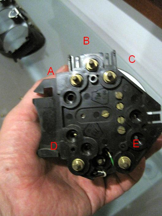
What signal are A, B, and C expecting? I am guessing one of them is expecting the ignition pulse at 1/2 the rpm. Which one? At what's fed to the others?
I am guessing that bottom D and E are for the boost gauge. One of them is 0-5v signal from KLR (or some other analog boost signal source). Which one?
04-28-2010, 09:50 AM
#3
Nordschleife Master
Thread Starter
Bump plus motivation: Here's somthing that can be done, with the right info and tools!

So the issue is that I am having hard time finding documentation about what signals are expected in what pins. I don't want to just try, I have no idea how easily one can fry these things. What I did notice is that the tachometer has two trim pots in it. I am guessing that the tacho could be recalibrated from those trim pots, one is probably gain and other one is offset?
So the issue is that I am having hard time finding documentation about what signals are expected in what pins. I don't want to just try, I have no idea how easily one can fry these things. What I did notice is that the tachometer has two trim pots in it. I am guessing that the tacho could be recalibrated from those trim pots, one is probably gain and other one is offset?
 04-29-2010, 09:50 PM
#5
At Connector B on the back of the cluster pin#2 is ground Brown/Black for the TAC, pin#4 is 12vdc Black/RED for the TAC, pin#3 is the DME output that drives the TAC which is DME pin #21 GR/Black
Cluster Connector A pins 1&2 drive the boost Gage. I do not know the DME TAC drive voltage scaling.
Cluster Connector A pins 1&2 drive the boost Gage. I do not know the DME TAC drive voltage scaling.
04-29-2010, 09:52 PM
#6
Nordschleife Master
Thread Starter
At Connector B on the back of the cluster pin#2 is ground Brown/Black for the TAC, pin#4 is 12vdc Black/RED for the TAC, pin#3 is the DME output that drives the TAC which is DME pin #21 GR/Black
Cluster Connector A pins 1&2 drive the boost Gage. I do not know the DME TAC drive voltage scaling.
Cluster Connector A pins 1&2 drive the boost Gage. I do not know the DME TAC drive voltage scaling.
05-04-2010, 09:47 PM
#7
Nordschleife Master
Thread Starter
Here's what I found for this particular tacho:
My photo pin A connected to ground
My photo pin B connected to a square-wave source
My photo pin C connected to 12v
In the car, the tacho signal is coming from the ignition. Therefore, the correct reading for the tacho should be the 30/Hz of the input signal.
Here are my empirical measurements:
Hz multiplier true RPM gauge RPM
21.2 0.5 636 750
33.3 0.5 998 1100
41.1 0.5 1234 1350
69.5 0.5 2086 2100
84.8 0.5 2544 2575
117.2 0.5 3516 3425
122.3 0.5 3670 3500
154.2 0.5 4625 4100?
169.6 0.5 5088 4800
222.6 0.5 6677 5450
244.7 0.5 7341 6000
245.9 0.5 7378 6000
In other words, very inaccurate after true 5000 rpm. After about 7400 true RPM, the gauge tilts and starts reading about 4000 rpm.
If this is a representative tacho, couldn't you read the 951 rpm from tea leaves near the redline with an accuracy comparable to that of the factory tacho? Or did I just buy an unusually defective unit from fleabay? Or both?