Clark's ENG-05 (belt removal procedure) updated for S2

 03-17-2009, 08:33 PM
#17
Instructor
Join Date: Sep 2002
Location: Selden, NY
Posts: 131
Likes: 0
Received 0 Likes
on
0 Posts
Auto Tensioner:
Mark Wrote:
To remove the timing belt, the spring tensioner must be removed. Remove the entire spring tensioner assembly as a unit. The three bolts on the face plate of the spring tensioner are not used to remove the unit. There are three bolts (which are very difficult to see) at the back of the tensioner near the block which must be removed to get the assembly out. [Note: These are three recessed 13mm nuts, two on the vertical right side of the tensioner (looking from the front) which can be found by feel without too much difficulty. The third nut is a bugger to find, and – crucially -- the timing belt idler that bolts on to the autotensioner unit _must_ be removed first to get a socket onto it. The third nut is positioned at the bottom of the idler, at about the 5 o’clock position (looking at it from the front). -Mark]
That's right, the tensioner must be removed. And it's a real B*tch to get the three bolts out. You can't seem them, you can barely reach them. And there are washers too. Two of the bolts are just moderate PITA to get at. The last one is the worst. I found that by moving the tensioner sprocket around, you can get a socket on the bolt.
Good luck installing the tensioner. That's even harder than taking it off.
Lastly, take a good long look at all the rollers, sprockets, etc. Replace any that are suspect. I am replacing a bunch of bent valves on my 87NA because the tensioner sprocket exploded.
Good luck,
Barry
04-08-2009, 09:06 AM
#18
Rennlist Member
Hi Barry,
Thanks for chiming in. I'll never forget how you came to my rescue when I took the axles and CV joints apart on my 83.
Unfortunately I had to put this S2 maintenance work on hold until I finished replacing the front rotors on both the S2 and the 951. Thankfully, that's now out of the way, rounded out allen head bolts and all.
During the timing belt job, are there any parts that tend to self destruct in the process, besides the ignition rotor? Thanks again everyone!
Last edited by Luis de Prat; 04-08-2009 at 09:34 AM.
 04-08-2009, 11:01 AM
#20

I remember when doing my timing belt that the clearance between the balance shaft gear and the belt cover was extremely close. Didn't feel like risking jacking up the belt so I just removed the crank bolt.
04-09-2009, 07:49 PM
#21
Rennlist Member
I'm reading through the procedure in preparation for this and it would help if someone could match the different pulleys/sprockets/idlers/rollers to each step. E.g. it doesn't say "crankshaft pulley" anywhere in the following diagram:
04-09-2009, 11:57 PM
#22
Rennlist Member
Thread Starter
Join Date: Jul 2001
Location: Brisbane, Australia (Formerly: Sunnyvale, CA)
Posts: 2,120
Likes: 0
Received 3 Likes
on
3 Posts
So the main steps are (before you get to the above diagram):
1) Remove PS pump and alternator belts
2) Remove crankshaft bolt
3) Remove PS belt pulley
You will then have alternator belt pulley/balance belt gear assembly sitting outermost on the crankshaft pin -- although the diagram above doesn't show the alternator belt pulley, presumably for clarity. The main purpose of that diagram is to show the path of the timing and balance belts, I think.
Last edited by Mark944na86; 04-10-2009 at 12:44 AM.
04-10-2009, 06:08 AM
#23
Rennlist Member
Okay thanks, but I'm still trying to match up the new parts to those in the diagram before taking stuff apart. Can you please help verify that the part numbers and photos below are correctly matched to those in the diagram?

Specifically:
1) Timing Belt Idler Pulley
944.105.241.04

2) Timing Belt Tensioner Roller (16V)
944.105.631.10

3) Balance Belt Idler Roller
944.102.277.06

4) Balance Belt Tensioner Roller
944.102.025.07

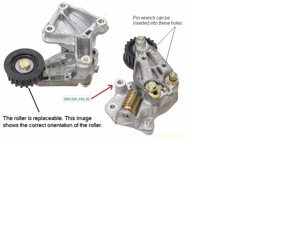
Lastly, I am at a loss as to where this roller is supposed to go:
5) Timing Belt Roller (description in PET catalog)
944.105.241.02

According to the diagram in PET, it looks like it should be mounted on the autotensioner assembly, as suggested here? ->
Your help is much appreciated!
NOTE: Roller pics from Pauer Tuning.
Specifically:
1) Timing Belt Idler Pulley
944.105.241.04
2) Timing Belt Tensioner Roller (16V)
944.105.631.10
3) Balance Belt Idler Roller
944.102.277.06
4) Balance Belt Tensioner Roller
944.102.025.07
Lastly, I am at a loss as to where this roller is supposed to go:
5) Timing Belt Roller (description in PET catalog)
944.105.241.02
According to the diagram in PET, it looks like it should be mounted on the autotensioner assembly, as suggested here? ->
Your help is much appreciated!
NOTE: Roller pics from Pauer Tuning.
04-10-2009, 06:31 AM
#24
Rennlist Member
Thread Starter
Join Date: Jul 2001
Location: Brisbane, Australia (Formerly: Sunnyvale, CA)
Posts: 2,120
Likes: 0
Received 3 Likes
on
3 Posts
You have all the rollers identified correctly.
#5 bolts onto the tensioner unit. There is even an arrow on the bottom pic with the part # pointing to where it mounts.
All the rollers are slightly different, so when you start removing the rollers already in there, just mark or remember where they came from. and you won'thave any trouble matching up with your new parts.
04-10-2009, 06:41 AM
#25
Rennlist Member
You have all the rollers identified correctly.
#5 bolts onto the tensioner unit. There is even an arrow on the bottom pic with the part # pointing to where it mounts.
All the rollers are slightly different, so when you start removing the rollers already in there, just mark or remember where they came from. and you won'thave any trouble matching up with your new parts.
#5 bolts onto the tensioner unit. There is even an arrow on the bottom pic with the part # pointing to where it mounts.
All the rollers are slightly different, so when you start removing the rollers already in there, just mark or remember where they came from. and you won'thave any trouble matching up with your new parts.
I also added the part number and arrow to the last image to illustrate what I was guessing was the correct placement of roller #5. Judging from your recent experience, I understand it really does go on the autensioner?
Lastly, are there any torque settings for all these rollers, or did you just fasten them tight enough?
Thanks again!
04-10-2009, 06:54 AM
#26
Rennlist Member
Thread Starter
Join Date: Jul 2001
Location: Brisbane, Australia (Formerly: Sunnyvale, CA)
Posts: 2,120
Likes: 0
Received 3 Likes
on
3 Posts
Thanks Mark, but I should've explained first that I have edited the above images to include the part numbers I believe correspond to each roller in the diagram.
I also added the part number and arrow to the last image to illustrate what I was guessing was the correct placement of roller #5. Judging from your recent experience, I understand it really does go on the autensioner?
I also added the part number and arrow to the last image to illustrate what I was guessing was the correct placement of roller #5. Judging from your recent experience, I understand it really does go on the autensioner?
Tight enough, but be careful whenever there are aluminium threads with the steel bolts...
04-11-2009, 09:39 AM
#27
Rennlist Member
14. If the balance shaft sprockets need to be removed (i.e. water pump or oil seals), the sprockets will have to be locked in place to allow the retaining nuts to be loosened. Use the Balance Shaft Pin Spanner to hold the sprocket while loosening the retaining nut. You can also use two large punches and a set of locking pliers to hold the sprocket, but this is very awkward. [Don’t even think about it – get the tool. You’ll also use it for the autotensioner. -Mark]
04-11-2009, 05:23 PM
#29
Rennlist Member
OK, I'm at the end of my rope here. I've been turning the engine at the crankshaft pulley and peeking through the window at the back of the engine but there's no sign of the "OT" letters and reference line illustrated in Clarks Garage.
The closest I've gotten are TWO lines about 1/4" apart. I've pulled the starter and peeked at the flywheel from there but I haven't seen any markings there either.
Could the TDC markings on the 944 S2 be different from those shown in Clarks Garage?
Also, when I turn the engine from the crankshaft pulley I get some resistance from the belts. Is this normal?
04-11-2009, 05:41 PM
#30
Instructor
Join Date: Sep 2002
Location: Selden, NY
Posts: 131
Likes: 0
Received 0 Likes
on
0 Posts
Hey,
If you have seen the two lines about 1/4" apart, the letters OT should be between them. Note that it is difficult to see the letters. I lay on the engine, shine a flashlight into the hole, and peer into the hole with one eye. After seeing the marks a few times it becomes easier.
Also, you can get fairly close to the marks by using the mark on the cam pulley. There is a mark on the pulley and a mark on the plastic cover behind the pulley. When those line up the engine should be close to TDC.
From Clarks Garage:
# Using the 15/16" or 24 mm deep socket and ratchet, rotate the engine in the clockwise direction using the crankshaft pulley bolt on the front of the engine until the letters "OT" appear in the clutch housing window.
NOTE
The picture below was taken on my own car. The "OT" is not really visible in the clutch housing opening due to the rust on my flywheel. However, some time ago, I painted the TDC line on my flywheel with red fingernail polish so it would be clearly visible. From the angle this picture is taken it appears that the alignment mark is slightly off from the alignment tab in clutch housing but it's simply due to the angle. To correctly align the mark for TDC you need to be looking directly down on the opening.
Many people have trouble locating the opening in the clutch housing for the TDC mark. You'll note in the picture the close proximity of the opening to the speed/reference sensor mounting bracket (sensors removed in this picture).
==
Also, regarding your parts lists and questions, the pulley that goes on the autotensioner is not smooth, it has teeth to match the timing belt. That's the pulley that exploded on my 87 and required me to rebuild the head, etc.
Finally, it SHOULD be difficult to turn the engine over by hand. That means the engine has good compression.
Good luck,
Barry