When you click on links to various merchants on this site and make a purchase, this can result in this site earning a commission. Affiliate programs and affiliations include, but are not limited to, the eBay Partner Network.
I have been working through the clarks garage instructions for sunroof repairs and diagnostics on my early car. The car was a bit of a basket case so I am not sure if the sunroof actually works but am trying to make it functional again. The header panel micro switch tests out fine but I am not recording voltage as of tonite at the switch in the console (though I am pretty sure I had voltage there a week ago when working through this). My radio/sunroof relay under the dash fell apart so it was replaced with a supposedly good used part. When I remove the relay to test the plug I get 12v with the key in the ignition at position 1 in the correct terminal on the relay (r?). When I turn the car on I am supposed to record 12V on the middle terminal as well but only record about 4.7 V at best and now really none at all. I read somewhere of someone with a similar problem and people suggesting a bad ground. I checked under the dash and behind the instruments and could not find the ground they were referring to but did find a yellow wire with a ring terminal that is spliced into a brown (ground) wire that is not attached under the dash. Guessing this might be the ground wire I attached it where the dash bracket bolts to the firewall/door area but it did not seem to solve my problem. Since I have incorrect or no voltage on the center plug terminal, I was thinking of tracing that wire back and replacing it to see if it would fix the issue. I can tell the wire (red/green) goes from the plug with the other wires into a heavier black wiring loom and behind the center of the dash but that is as far as I have been able to trace it. Does anyone know where this ultimately ends up so I could test my theory with some wire before pulling apart the dash? Any other ideas what my issues may be?
When you say middle terminal has 4.5V or none, are you referring to the switch, or the relay? On the relay, this is the speed sensor signal coming in and alternates between 5v and ground depending on the position of the front left wheel. If this is the one you are measuring, it is working correctly.
Start at the relay socket with the relay removed. You should have 12V at terminal R with the key in. You should have 12V at terminal R and terminal 15 with the ignition on.
I was referring to the socket for the radio/sunroof relay just under the dash next to the console on the drivers side. There is 12v on the outer terminal with the key in the ignition like it is supposed to have....have measured just under 5v and sometimes nothing on the center terminal which is supposed to be 12v with the key at position 2 (start) according to clarks instructions. I currently have nothing at the actual switch in the console but could of sworn I had some voltage on the middle of the 6 pins a few weeks back when I started the whole ordeal.
terminal R is measuring correctly..it is the second pin with the key at position 2 (start) that is measuring either 5v or now none. I took all these measurements with the relay removed.
.have measured just under 5v and sometimes nothing on the center terminal
This is terminal A and that is correct for the relay socket. Clark's is incorrect on having 12v at this point. This signal comes from the speedometer where there is a hall effect sensor which detects the speed of the vehicle for the automatic sunroof lock function. This signal provides three approximately 5V pulses per front-left tire rotation. The voltage on the terminal depends upon where the wheel is in it's rotation. If it's currently zero, move the car a foot and it will change to 5V (ish.)
I tested pin 15 and got the correct voltage there so voltage to the relay is correct. I checked fuses and fuse 7 in the upper block (radio, cig lighter) was blown so I replaced it thinking maybe the sunroof could possibly be tied to it since the relay was called a sunroof/radio relay...no luck. I have no power at the sunroof switch/plug it seems.
So, you have power at relay terminal R with the key inserted, and power at relay terminal 15 and relay terminal R with the ignition on.
Next step: Insert Relay. With the key inserted you should now have power on pin 2 of the switch (one of the center pins of the switch.) and with the ignition on you should have power on pin 1 (the other center pin of the switch.)
A) If no power to pin 1 with the ignition on, the brown/green wire is broken. We can deduce this because the relay itself connects relay pin 15 directly to relay pin 2, which is wired to switch pin 1 by the brown/green wire..
B) If you have no power on switch pin 2 with the key inserted but ignition off, either the blue/black wire or the relay itself is broken.
C) If both of these are good, make sure the power on pin 2 of the switch turns off when the ignition is on. If it doesn't, the relay is broken.
If these tests are good, there is correct power getting to the switch. Remove the switch and test per Clark's instructions (resistance measurements.)
That is correct...I have no power on either of the pins on the switch (the center two). I found a posting where someone had the wires incorrect in the switch and it seems mine may have been messed with at one point possibly too as I think some of them were wrong though it is worth noting the person that referenced it was working on a later 944 and so I am not sure if the wire colors/switch positioning is the same. Thanks so much for your help BTW.
OK, switch terminal 1 should be a brown wire with a green stripe, and relay terminal 2 should be the other end of that same wire. With the ignition on, you have voltage at relay terminal 15. With the relay in, that voltage is directly connected to relay terminal 2. The wire should be connecting it to the switch. If not, the wire is severed along the way.
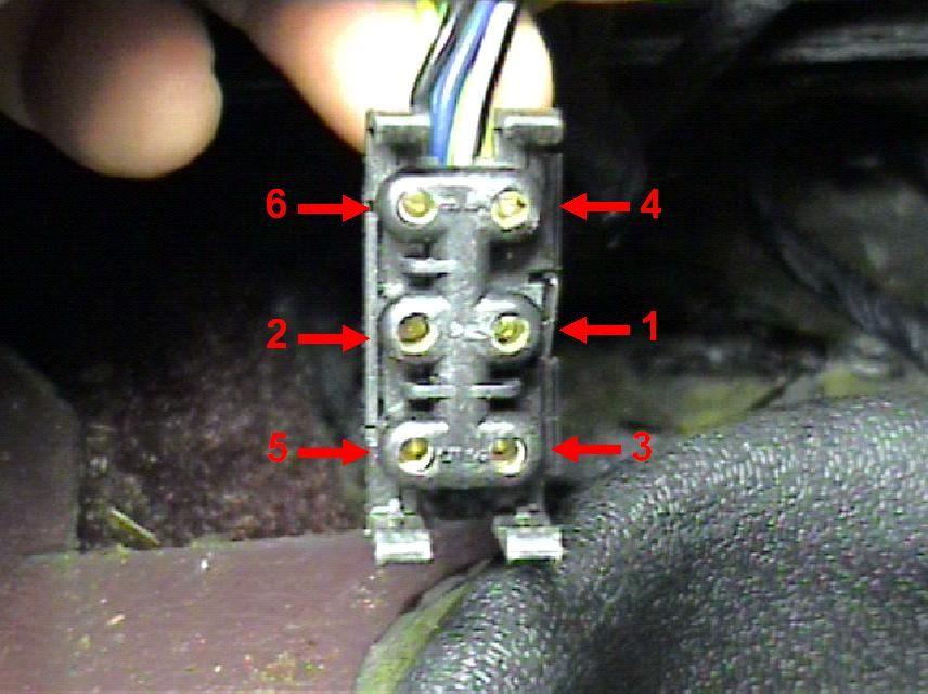
Wire colors on the switch should be:
1 - Brown w/ Green stripe
2- Blue w/ Black Stripe
3- Red w/ Green stripe
4- Grey w/ Green Stripe & Black w/ Yellow Stripe
5- Grey w/ Black Stripe
6- Black
I redid all the switch wires to make sure they are correct...all the wires match the colors you specified except for my pin 1 (blue/green...not brown/green) but the wire going to pin 2 on the relay is the same color. I checked the continuity of that wire at the back of the relay plug and at the switch pin 1 and got 0.02 indicating that the wire is likely not broken? I have no voltage at the switch in pin 1 or 2.
On the relay, pin 15 should be directly connected to pin 2. Check that this is the case with your multimeter. If not, the 1984 schematic we all use is not correct for your car. On my relay (1985/1, relay pin 15 to relay pin 2 (both on the relay itself) is a copper trace and should have almost no resistance. BTW, pin 1 of the switch should only have voltage with the ignition on.
Well I can confirm that the motor and switch work...I think the relay may be the issue though but I have got to try your info you just provided. I ran a wire directly from R of the relay terminal to pin 1 of the switch (removed the pin) and the sunroof motor functioned in one direction at position 1 of the key. I ran the same wire to pin 2 and the sunroof functioned in both directions at position 2 on the key. I plugged the relay in before doing this and with just enough gap between the relay and plug to touch the relay pins with the end of the multimeter probe, I measured 12v at R like expected but nothing at pin2 on the relay side with the key on which is not correct I think. The car is an early 85 (I think sep 84 build).
Step on your brakes and see if your brake lights come on. If not, fuse 8 in the lower fuse panel is likely blown. Fuse 8 also supplies terminal 15 of the relay. If the fuse is OK, try running your wire from terminal 15 of the relay instead of R to the switch and see what happens.
 11-20-2021, 02:14 AM