When you click on links to various merchants on this site and make a purchase, this can result in this site earning a commission. Affiliate programs and affiliations include, but are not limited to, the eBay Partner Network.
trying to put together a 944S project for first time. After engine install, I get "no Tach Bounce" and also fuel pump does not engage with ignition "on", although the fuel pump works when doing the DME relay bypass jumper trick (it's a new relay).
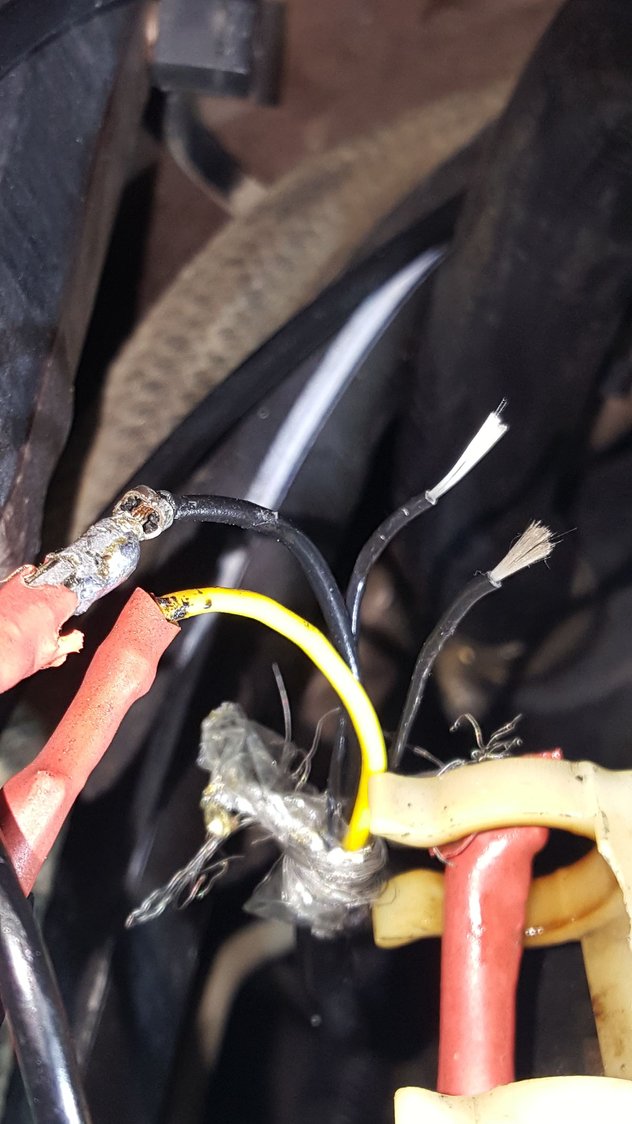
I thought the issues could all be due to the speed/ref sensor. I initially did a quick solder of the wires because the connector fell apart. On the speed/ref sensor side there are 5 wires 3-black wires, one yellow and the metal shielding. The two smaller black 'wires' appear to be fiber after striped (see pic). There are only the 3 expected wires on DME harness side of the connector - white, brown and the metal shielding. Any ideas for the two small black fiber 'wires and could they be the culprit? The wiring diagram didn't help
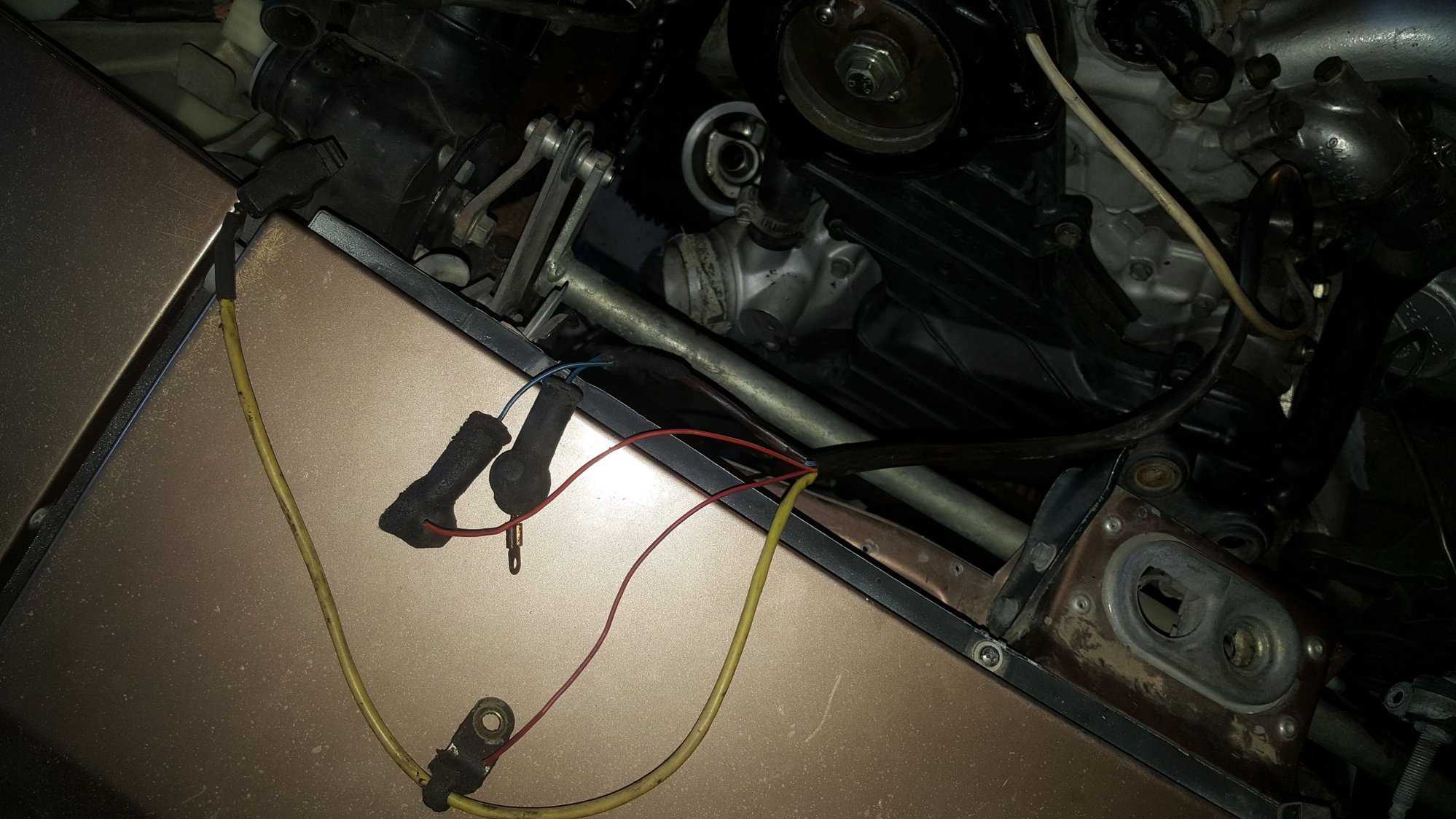
Also, since on the 944S wiring...there are two red wires that were cut near the end of the wiring harness, near the oil pressure sender connections, any ideas on what they go to ( pic below) Thanks!
I believe I stumbled on the answer for the 'extra' black wires on the speed sensor side - they are "drain wires" associated with the metal shielding to reduce noise. Although I'm trying to get this started for the first time after I purchased someone else's project...since this is a sensitive and critical component, I'm sure it is best to just order a new sensor that provides the proper connections/termination at the connector ..rather than my quick solder.
If anyone has an idea on the other red harness wires...I'd appreciate it!
Red harness wires are for the power steering switch I believe. However I don't have the schematic here in front of me. I can send them your way next week when I return home.

 03-27-2018, 07:04 PM