
Hi / Lo headlight Switch repair thread
 08-11-2009, 03:25 PM
#1
Team Owner
Thread Starter
Hey Guys
i finally got my headlight hi /lo switch repaired and functional. I thought I would put this thread together to help future people in my situation. Please add stuff as you see fit. I initially got information from a great thread that John posted but I felt it lacking in explanation so thought I would expand on it and give it the usual tongue in cheek Rennlist flavour.
The Isssue : All of a suden my hi / lo switch stopped working and had to drive home with high beams on when I was 20 miles from home . Made me instantly popular with my neighbors. - NOT ..
The first step is to inspect the switch to verify this is the problem. If your switch now does not even click back and forth you can skip right to removal as it is surely melted.
I am not going to go into a lot of detail with the the removal of the switch . i am sure there are threads for this. It is very easy and if you can't do this part then I would not suggest atempting the fix.
Inspection :
take off the steering wheel, horn contact upper and lower cowl.
inspect the contacts of the switch rom the left side of the steering wheel area. You may need a magnifying glass and flashlight, The hi / lo beam switch is the white plastic part of the assembly with the copper contacts.
If you are not sure what I am talking about and you are feeling confident just go ahead and remove the switch for a closer inspection or replacement .
Removal:
Remove and mark all the connections to the switch . You wiil have to remove the headlight switch which requires some snap ring pliers or a good pair of fine needlenose to turn the nut with the holes in it. Just spin off the **** to get access to the retaining nut. once the hedlight witch has been removed mark or write down all your connectors.
Undo the two slotted screws holding in the hi/lo switch and remove the assembly. Put in your new one at this point or get ready to get down to business and fix it , saving yourself 150.00 and the order and wait time.
Switch fundamentals.
The switch as very basic in design but might be a challenge to figure out after it has melted.
Placing the switch with silver actuating bar at the bottom : this bar has a plunger at the end that is 2.5mm by 2.5mm by 6mm from the top of the metal bar to the end. This is the piece that has most likely melted down.
By design the middle contact being the current supply contact will rest against the lower contact while the car high beam is on . when the switch is pulled forward it pushes the metal bar and plunger up through a hole that is 2.5mm by 2.5 mm in the high beam contact, pushing the middle current carrying contact off the lower contact ( high beam ) to the upper contact ( low beam ) .
The spring tension from the midle current carrying contact pushes the plunger back and reconects with the high beam when the switch is pushed back.
( This is why it goes to high beam when the switch melts. )
Now that you know the basics of the switch you may be able to make some repairs to intermitent switch action even if it has not melted.
Picture One and Two :
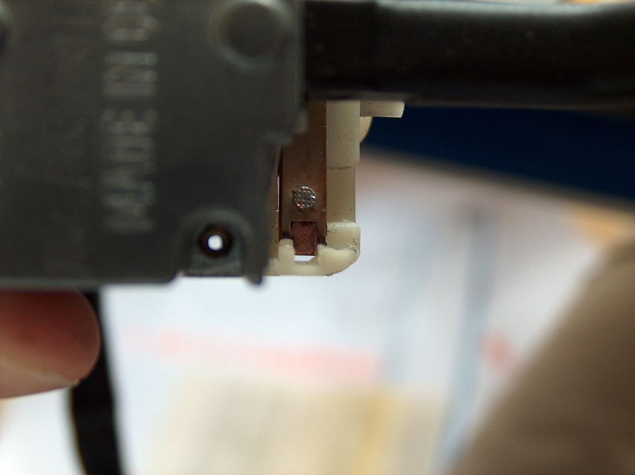
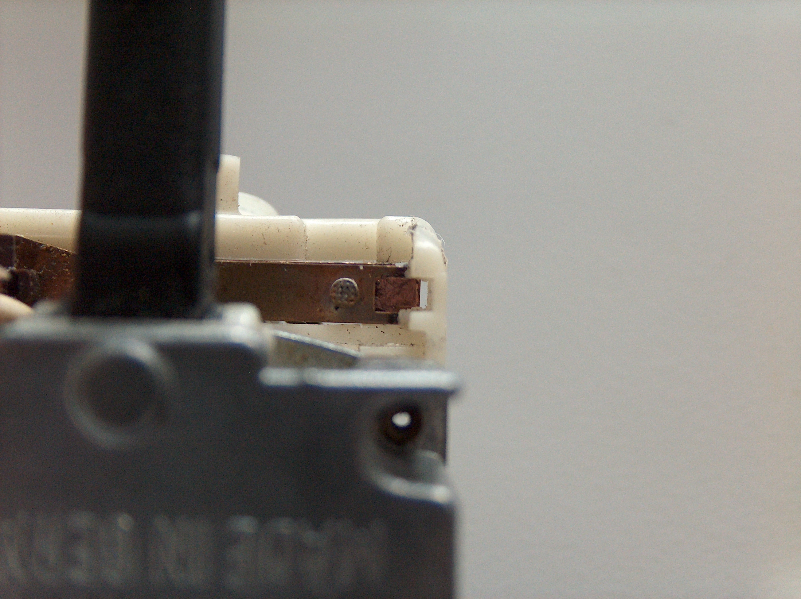
Switch showing actuator bar removed ( removed by sliding out with a flat blade screwdriver from the back of the switch ) . Take care not to break the plastic fingers at the base of the actuator ( opposite end to plunger ) or you are pretty well screwed with this repair.
The picture shows the cut out in the high beam contact for the plunger to pass through, Also there is a cut out in the white plastic guide for the plunger to slide up and down in.
Close inspection also reveals the high beam contact goes through a horizontal slot in the white plastic assembly . This limits the high beam contact from going to far up or to far down.
The next post we will get into the repair of the switch.
i finally got my headlight hi /lo switch repaired and functional. I thought I would put this thread together to help future people in my situation. Please add stuff as you see fit. I initially got information from a great thread that John posted but I felt it lacking in explanation so thought I would expand on it and give it the usual tongue in cheek Rennlist flavour.
The Isssue : All of a suden my hi / lo switch stopped working and had to drive home with high beams on when I was 20 miles from home . Made me instantly popular with my neighbors. - NOT ..
The first step is to inspect the switch to verify this is the problem. If your switch now does not even click back and forth you can skip right to removal as it is surely melted.
I am not going to go into a lot of detail with the the removal of the switch . i am sure there are threads for this. It is very easy and if you can't do this part then I would not suggest atempting the fix.
Inspection :
take off the steering wheel, horn contact upper and lower cowl.
inspect the contacts of the switch rom the left side of the steering wheel area. You may need a magnifying glass and flashlight, The hi / lo beam switch is the white plastic part of the assembly with the copper contacts.
If you are not sure what I am talking about and you are feeling confident just go ahead and remove the switch for a closer inspection or replacement .
Removal:
Remove and mark all the connections to the switch . You wiil have to remove the headlight switch which requires some snap ring pliers or a good pair of fine needlenose to turn the nut with the holes in it. Just spin off the **** to get access to the retaining nut. once the hedlight witch has been removed mark or write down all your connectors.
Undo the two slotted screws holding in the hi/lo switch and remove the assembly. Put in your new one at this point or get ready to get down to business and fix it , saving yourself 150.00 and the order and wait time.
Switch fundamentals.
The switch as very basic in design but might be a challenge to figure out after it has melted.
Placing the switch with silver actuating bar at the bottom : this bar has a plunger at the end that is 2.5mm by 2.5mm by 6mm from the top of the metal bar to the end. This is the piece that has most likely melted down.
By design the middle contact being the current supply contact will rest against the lower contact while the car high beam is on . when the switch is pulled forward it pushes the metal bar and plunger up through a hole that is 2.5mm by 2.5 mm in the high beam contact, pushing the middle current carrying contact off the lower contact ( high beam ) to the upper contact ( low beam ) .
The spring tension from the midle current carrying contact pushes the plunger back and reconects with the high beam when the switch is pushed back.
( This is why it goes to high beam when the switch melts. )
Now that you know the basics of the switch you may be able to make some repairs to intermitent switch action even if it has not melted.
Picture One and Two :
Switch showing actuator bar removed ( removed by sliding out with a flat blade screwdriver from the back of the switch ) . Take care not to break the plastic fingers at the base of the actuator ( opposite end to plunger ) or you are pretty well screwed with this repair.
The picture shows the cut out in the high beam contact for the plunger to pass through, Also there is a cut out in the white plastic guide for the plunger to slide up and down in.
Close inspection also reveals the high beam contact goes through a horizontal slot in the white plastic assembly . This limits the high beam contact from going to far up or to far down.
The next post we will get into the repair of the switch.
Last edited by theiceman; 04-29-2021 at 03:59 PM.
 08-11-2009, 03:55 PM
#2
Team Owner
Thread Starter
The key to the whole thing is the actuator.
Picture one: The plunger after it has been removed. You may need a magnifying lighted ring if you er , are of advancing years ..over 40 .. and looking at such small things becomes difficult.
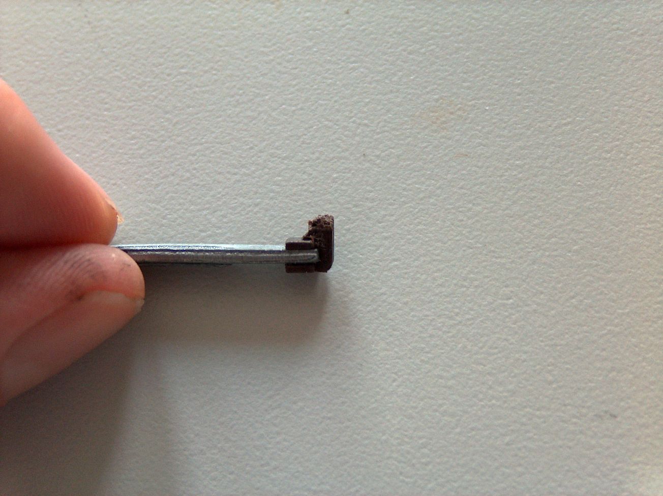
As you can see it is completely melted. What we are trying to accomplish is to build the plunger back up to original specs. so it can again be functional. remember we have to fit inside our original specs of 2.5mm by 2.5mm by 6mm so a Vernier gauge would be very helpful. After you get the actuator out make sure to clean all the old melted actuator out of the switch. if you don't the repaired switch may bind. I used a dental pic and i worked great for this.
The first step for me was to grind it completely flat ( or sand it ) . to give us a base to work on.
Then i drilled a very small hole in the flattened area and also into my piece of donor plastic that happened to be 2.5mm by 2.5mm.... bonus.
Then i used a couple of pieces of LED lead to act as a pin to put the 2 pieces together.
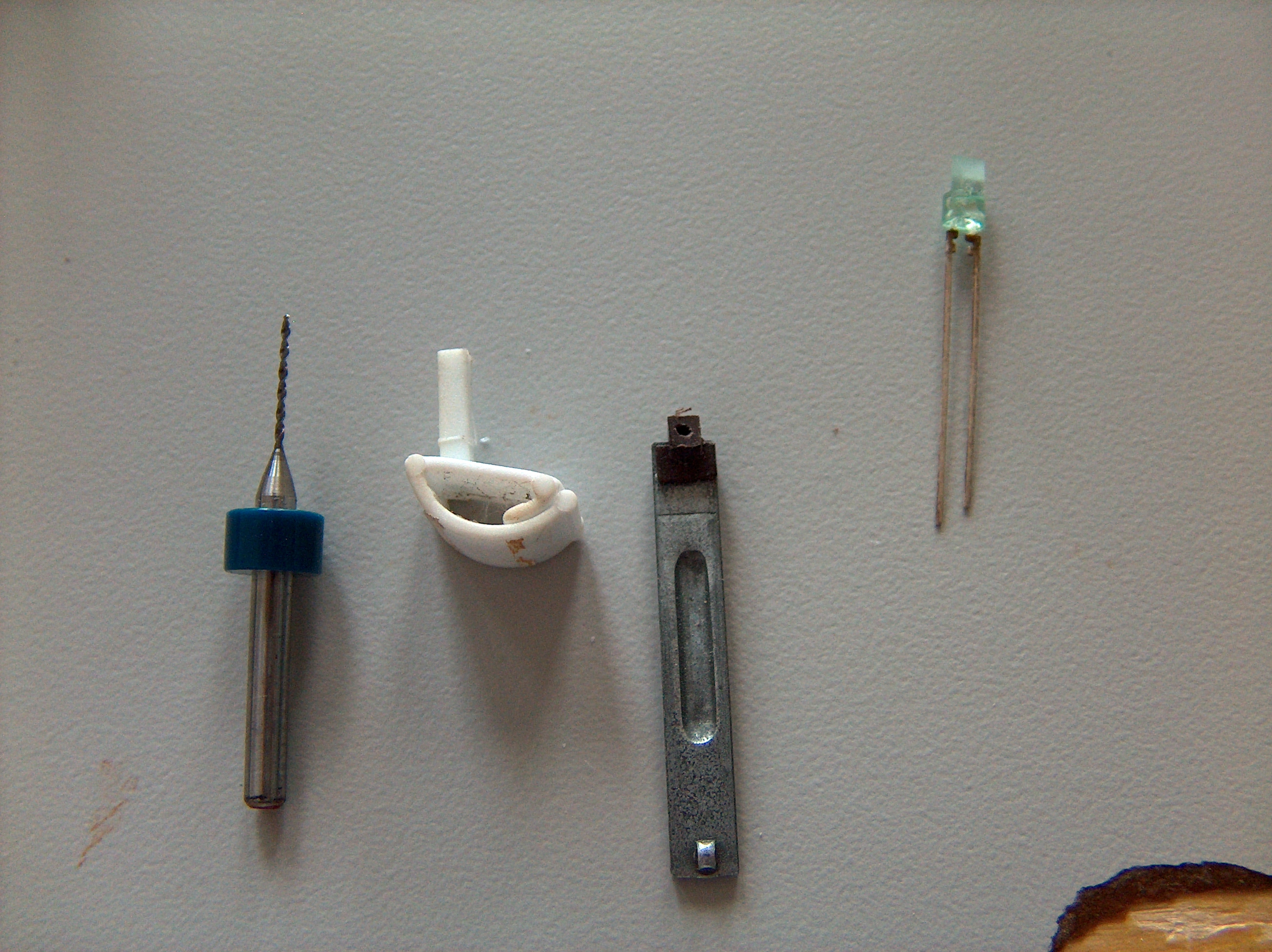
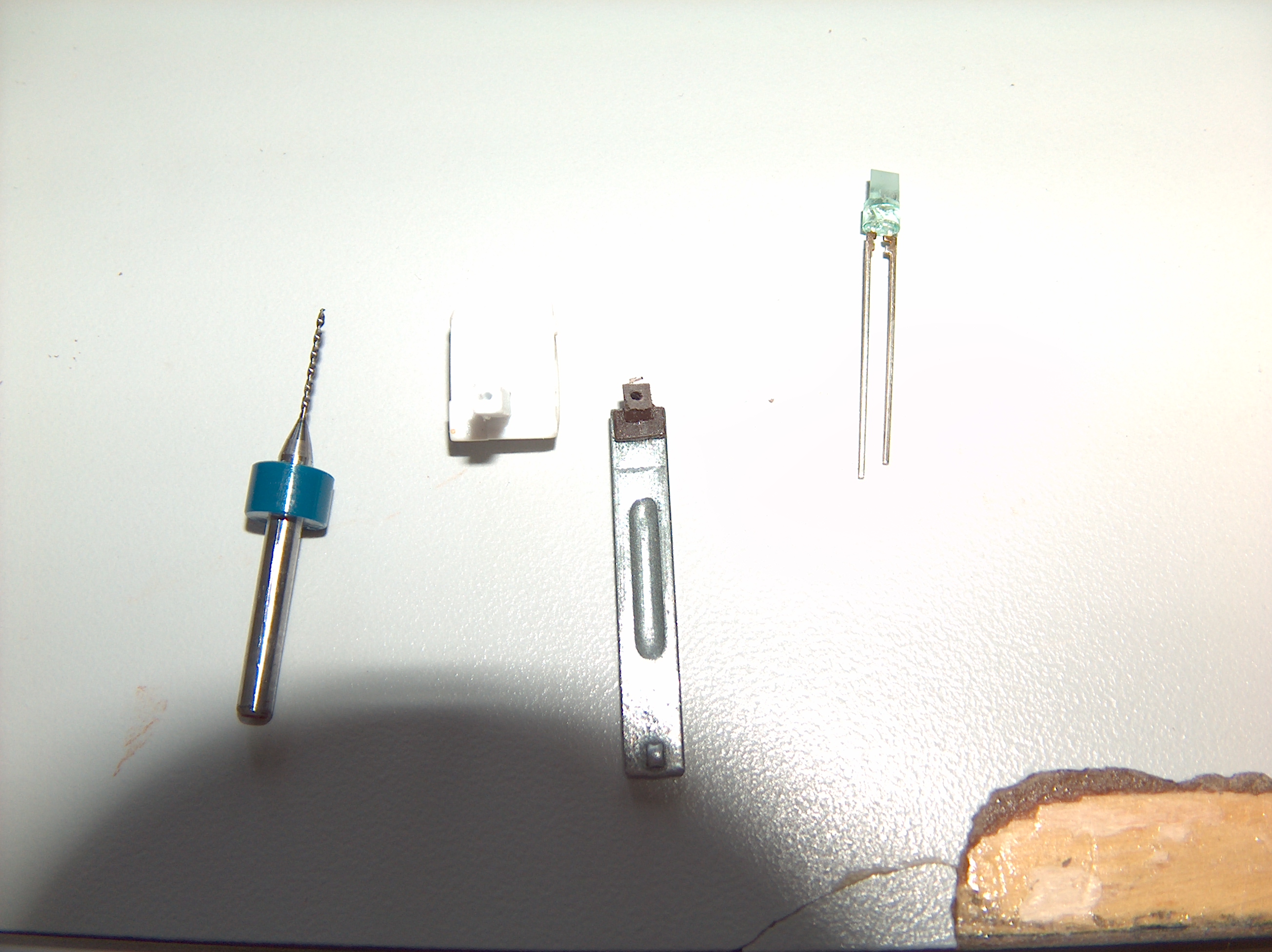
actuator base ground flat with hole drilled in. small drill used in my dremel , steady hand needed for sure. Plastic donor piece from a plastic window clip. LED used as donor clip . I ended up using a small staple folder over but it all depends on the hole size.
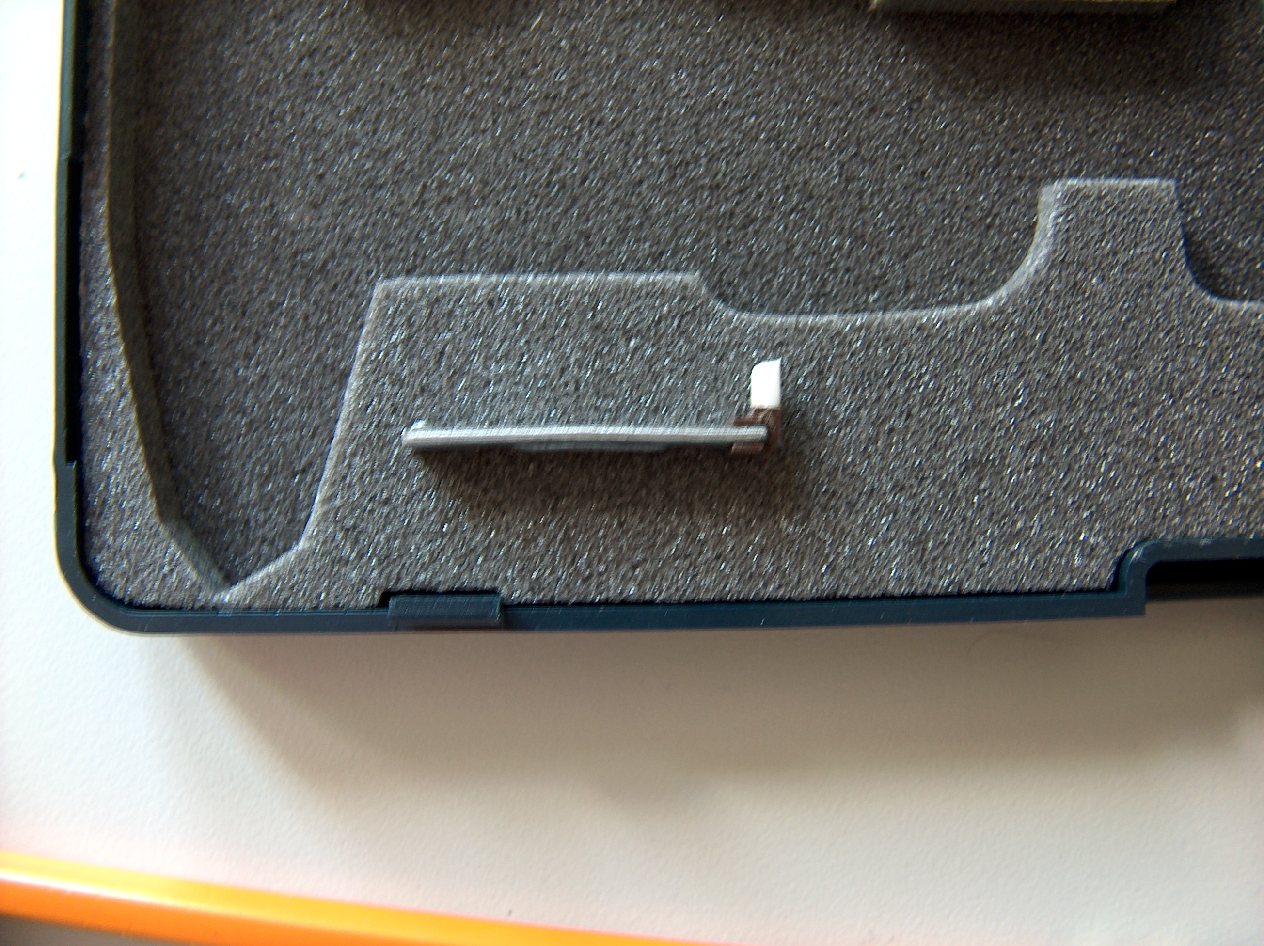 . Assembled piece all ready for test fitting.
.. and I think this is the most important. After assembly i took it apart and mixed up some JB weld. put a small amount in between the sections and glued them together. Then I coated the whole think in JB weld filling the cracks and gaps.
After 24 hours of drying time I grinded it back down and trimmed it to original dimensions. Fine sand paper or any fine sander will do but it is important to keep it square and to original dimensions.
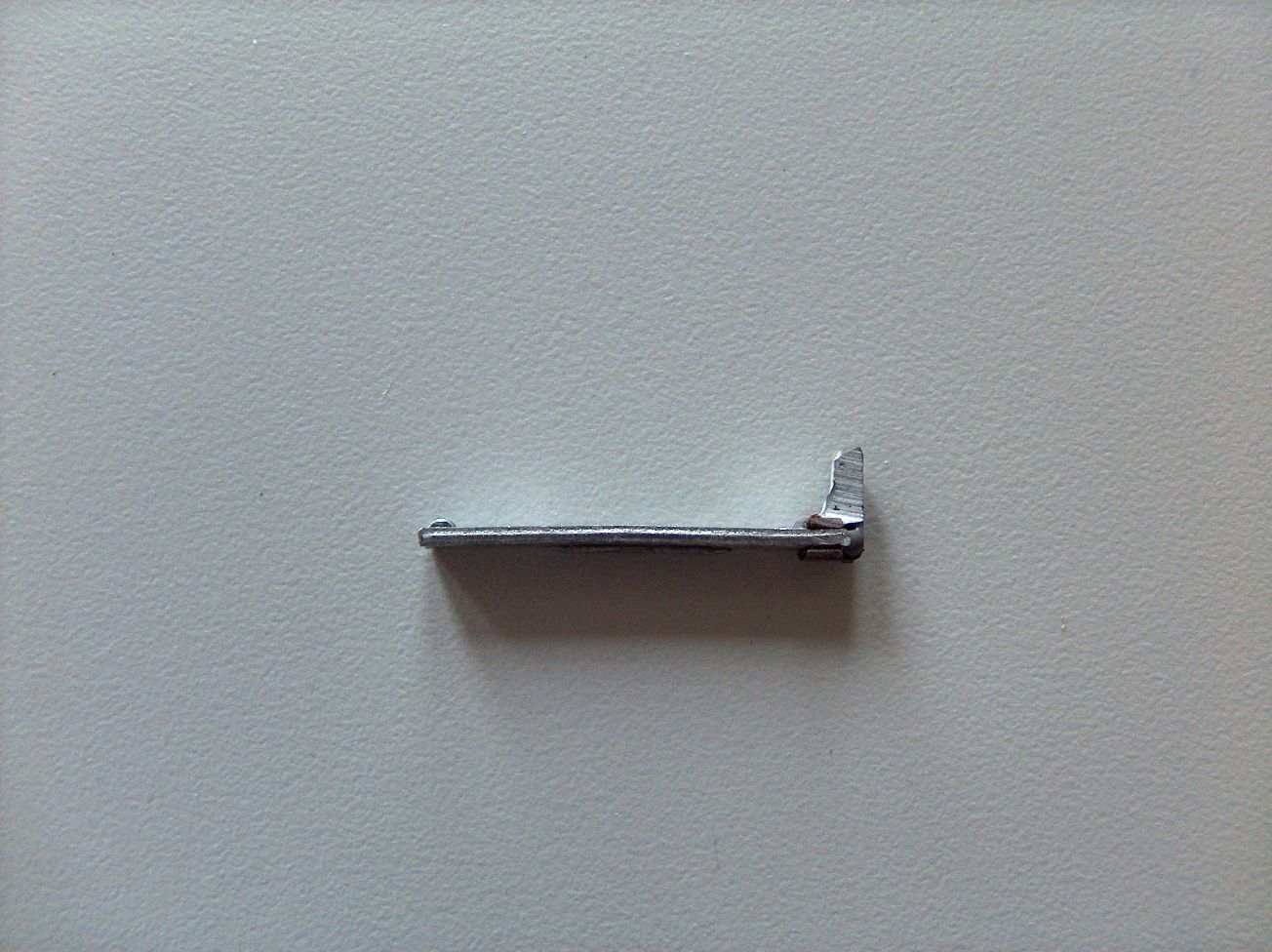
After the final trimming and testing you carefully put back the plunger and arm assembly .Pull up the contacts slide in the plunger and carefully maneuver all back into position. make sure it does not bind, even when you pull the lever to activate the secondary set of high beam flasher contacts.
add a drop of dielectric grease to prevent arcing and smooth operation and you should be set to go ..... almost ...
check with a meter before assembling.
Picture one: The plunger after it has been removed. You may need a magnifying lighted ring if you er , are of advancing years ..over 40 .. and looking at such small things becomes difficult.
As you can see it is completely melted. What we are trying to accomplish is to build the plunger back up to original specs. so it can again be functional. remember we have to fit inside our original specs of 2.5mm by 2.5mm by 6mm so a Vernier gauge would be very helpful. After you get the actuator out make sure to clean all the old melted actuator out of the switch. if you don't the repaired switch may bind. I used a dental pic and i worked great for this.
The first step for me was to grind it completely flat ( or sand it ) . to give us a base to work on.
Then i drilled a very small hole in the flattened area and also into my piece of donor plastic that happened to be 2.5mm by 2.5mm.... bonus.
Then i used a couple of pieces of LED lead to act as a pin to put the 2 pieces together.
actuator base ground flat with hole drilled in. small drill used in my dremel , steady hand needed for sure. Plastic donor piece from a plastic window clip. LED used as donor clip . I ended up using a small staple folder over but it all depends on the hole size.
. Assembled piece all ready for test fitting... and I think this is the most important. After assembly i took it apart and mixed up some JB weld. put a small amount in between the sections and glued them together. Then I coated the whole think in JB weld filling the cracks and gaps.
After 24 hours of drying time I grinded it back down and trimmed it to original dimensions. Fine sand paper or any fine sander will do but it is important to keep it square and to original dimensions.
After the final trimming and testing you carefully put back the plunger and arm assembly .Pull up the contacts slide in the plunger and carefully maneuver all back into position. make sure it does not bind, even when you pull the lever to activate the secondary set of high beam flasher contacts.
add a drop of dielectric grease to prevent arcing and smooth operation and you should be set to go ..... almost ...
check with a meter before assembling.
Last edited by theiceman; 04-29-2021 at 04:06 PM.
08-11-2009, 04:15 PM
#3
Team Owner
Thread Starter
Well your switch should be repaired but i would not connect the battery yet. The reason your switch melted in the first place was because you were carrying WAY to much current in the switch. I actually melted the switch AGAIN right after I put it back together. Either i did not clean the contacts properly or I still had a short somewhere.
Not finding a short I decided to put in a relay system to prevent burning it out again. That part was pretty easy.
I bought a couple of relays and sockets and hooked one up to the lo beams and one up to the high beams.
The hot side of the one set of contacts i connected directly to the battery ( red wire,) the other side of the contacts I fed to the input of the fuses where i removed the original input from the switch ( yellow wire and white wire ) . This allows me to use the factory fuses on the lights.
The switch wires i removed from the fuse block ( yellow and white ) I ran to a terminal block I added , there I attached the coil side of the relay.
The ground side of the coil I just grounded to the body. i am not to pleased with that and will move it eventually but it did work.
All in all a successful project.. relays work fine, switch works fine . headlights work fine ..
Switch .. 150.00 USD
Relay Kit 25.00 USD ...
My repair .... 12.01 CAD. and fixed in 2 days..
Good luck and I hope this helps someone down the road.
Last edited by theiceman; 04-29-2021 at 04:07 PM.


 08-11-2009, 11:43 PM
#7
Rennlist Member
I thought the diagram rusnak posted on the other thread may be helpful, unless it doesn't apply to your work here. If it does, it would put pertinent electrical info up here on the relay upgrade, which is something most of us should do.
(PS-I thought this was the "price check" forum? This seems technical in nature.... )
)
(PS-I thought this was the "price check" forum? This seems technical in nature....
)
Trending Topics
08-11-2009, 11:57 PM
#9
Team Owner
Thread Starter
okay don't make me put the little numbers on the relays to please .. 
Last edited by theiceman; 01-09-2013 at 10:14 AM.
08-12-2009, 12:18 AM
#10
Team Owner
Thread Starter
This is different from Ians. I wanted to use the stock fuses and block to keep things simple and to simplify instalation.
Yes you should definitely all do this if you haven't already and save your switch. I was looking on Pelican and I found a thread about a kit that is for sale on pelican for 25.00 . This kit is wired in EXACTLY as I did mine, sounds like the guy who invented it has similar experience and desire as me.
Simple instalation with keeping as close to stock as possible.
08-12-2009, 01:11 AM
#11
Rennlist Member
I forgot about that kit, it is from Jwest Engineering. He does first class stuff, IMO. At least his shifter is, every bit the equal to a Wevo, I feel.
I probably ought to do this, and for $25 to have the components shipped to me with no pain, pretty inexpensive.
I probably ought to do this, and for $25 to have the components shipped to me with no pain, pretty inexpensive.
08-12-2009, 02:05 PM
#12
Team Owner
Thread Starter
Yeah Ed that was him. For 25.00 you are right it is a cheap and simple mod. Apparently the relays will allow you to run up to 100w bulbs if you want to and use stock wiring . For canyon carver guys I would definitely recomend it . For me stock 55/60 does the job fine
08-12-2009, 04:08 PM
#13
I haddah Google dat
Rennlist Member
Rennlist Member
I have the JWest relay kit, which is what I mentioned in the other headlight relay thread. I have not seen the Markus Sucro one, so I can't compare them. I like the convenience of just bolting the thing in with all of the wires already cut and crimped for you. It's a 10 minute job.
I noticed that the high beams are brighter, but not much else. Others have reported brighter low beams. I was mainly thinking of increased reliability rather than performance.
I noticed that the high beams are brighter, but not much else. Others have reported brighter low beams. I was mainly thinking of increased reliability rather than performance.
08-12-2009, 04:12 PM
#14
I haddah Google dat
Rennlist Member
Rennlist Member
I have the JWest relay kit, which is what I mentioned in the other headlight relay thread. I have not seen the Markus Sucro one, so I can't compare them. I like the convenience of just bolting the thing in with all of the wires already cut and crimped for you. It's a 10 minute job.
I noticed that the high beams are brighter, but not much else. Others have reported brighter low beams. I was mainly thinking of increased reliability rather than performance.
I noticed that the high beams are brighter, but not much else. Others have reported brighter low beams. I was mainly thinking of increased reliability rather than performance.
Search link:
https://rennlist.com/forums/911-foru...eadlight+relay
Breadcrumb trail for future wayward souls
Search terms:
"headlight switch repair"
"home-made headlight relay"
"headlight relay"
"headlight flasher switch"
Oh duh! I just found the "tags" button.
Last edited by rusnak; 08-12-2009 at 08:05 PM.
08-12-2009, 07:18 PM
#15
Team Owner
Thread Starter
looking at your relay wire connections I assumed it was that kit. I am fortunate enough to have a liquidation outlet around the corner that had the relays and socket. You are right , it is about a ten minute job.