
What is the difference between a Porcupine and a Porsche ?
 08-07-2009, 09:05 AM
#16
Drifting


 08-07-2009, 12:55 PM
#18
Rennlist Member
My switch had similar problems, but wasn't fried like Iceman's. I was able to bend the strip to make contact on high and low beams. I did install Marcus Sucros relay kit which has helped immensely. Two benefits: Current doesn't flow into the stalk like it used to and my dash lights are much brighter. If the switch ever craps out again, I will opt for a new one. So far all is good.
08-07-2009, 08:47 PM
#19
Team Owner
Thread Starter
Ron do you have the instructions still for the relay kit? or does anyone ? I have a relay and socket sitting on the shelf and should wire it in before I put this back together . If someone wouldn't mind scanning it and sending to ne I would certainly appreciate it.
I will eventually get this kit everyone speaks of but I am on vacation next week and would like to have my car on the road.
also what is the relay rated at ? thanks.
my email address is cyoung1661@rogers.com if someone would like to send me a scan ..
many thanks ..
I will eventually get this kit everyone speaks of but I am on vacation next week and would like to have my car on the road.
also what is the relay rated at ? thanks.
my email address is cyoung1661@rogers.com if someone would like to send me a scan ..
many thanks ..
08-07-2009, 09:08 PM
#20
I haddah Google dat
Rennlist Member
Rennlist Member
I have the West Engineering relay kit, but I think I just threw the instructions out on Tuesday (trash pick up day). It uses two relays, one each for low and high beam. The relays look like typical automotive relays. Two 100 watt bulbs would be about 16 amps total I believe.
You remove the top wire from the headlight circuit, and these become the switching circuit. The powered circuit (switched) pulls power directly from the battery to the lights.
http://www.jwesteng.com/porsche/911/hl_relay.htm
https://rennlist.com/forums/911-foru...ght-relay.html
I'll go back and take some more pics. I'll need a day to get back to post them.
08-07-2009, 10:14 PM
#21
Addict
Rennlist Member
Rennlist Member
Clive
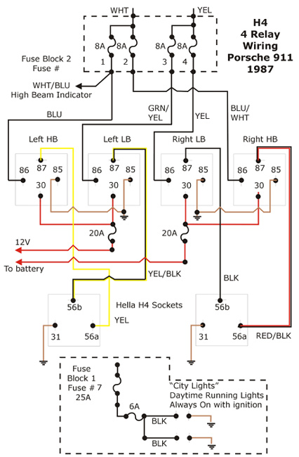
Here is a 4 relay diagram. I have 1 for each hi & low filament. It makes a very satisfying snap when I turn them on. Overkill: Sure but relays are pretty cheap & I can install flamethrower bulbs. The city lights make a nice daytime driving light. I rewired each bucket with 12 awg wire.
The write up: H4 Conversion
Diagram:
Ian
08-08-2009, 12:24 AM
#22
Team Owner
Thread Starter
Thanks guys .. some dissapointing news tonight ... i tested my switch and it worked perfectly with the meter .. put it in the car .. tested it , everything looked fine... i was inspecting the other componens in the area and POOF .. all my work literally went up in smoke ..... AGAIN .....
given it tested fine me thinks I have a short. Strange thing is none of the fuses blew ... pretty easy circuit though so I will do some testing next week.
nice diagram Ian thanks and definitely overkill.
I basically was wondering where the relay gets spliced in and does it go down by the other relays or up under that dash. I guess I could wire in at least two realys .. for high and lo beam . i was also curious wether the elay kit had you rewire frsh wire from the battery to feed the lights or wether it was a basic switch bypass. That is why i think I would have found the original instructions handy ..
After my second melt down i definitely think there is more to this. I will be sure to keep everyone posted...
08-08-2009, 08:03 AM
#23
Addict
Rennlist Member
Rennlist Member
Clive
I went for overkill after driving my car one night down from Apsley. On dark rural roads, I realized how bad the H5s were. The light output was dangerously low imho. So I bought H4s & then looked at the wiring in the bucket. The first 6 inches was blackened & the insulation was brittle from the heat - and that was with the stock 55/80 lamps. The wire was 18 awg by the look of it. I use 80W/100W lamps now & they are great.
Here is a 2 relay diagram that was posted:

from this thread
Ian
I went for overkill after driving my car one night down from Apsley. On dark rural roads, I realized how bad the H5s were. The light output was dangerously low imho. So I bought H4s & then looked at the wiring in the bucket. The first 6 inches was blackened & the insulation was brittle from the heat - and that was with the stock 55/80 lamps. The wire was 18 awg by the look of it. I use 80W/100W lamps now & they are great.
Here is a 2 relay diagram that was posted:
from this thread
Ian
08-08-2009, 10:23 AM
#25
Team Owner
Thread Starter
Thanks Guys
Gonna take a day off and go visit some friends today .. I have a feeling I iwll find some old wiring when I inspect the bucket .. John that looks like alot of reading but i think it will definitely help.
Gonna take a day off and go visit some friends today .. I have a feeling I iwll find some old wiring when I inspect the bucket .. John that looks like alot of reading but i think it will definitely help.
08-08-2009, 10:22 PM
#26
I haddah Google dat
Rennlist Member
Rennlist Member
Iceman, no splicing needed. You take the top wires out of the high and low beam (white and yellow on mine), and they are connected to the relay (#86 I think on Ian's diagram). #85 to ground and #30 to power (battery). #87 goes to the headlights, so you connect your old wires to #87 on the relays. The thing to double check is whether the top or bottom wire on your fusebox is the one that goes to either the switch or the headlight. The one with 12v current is the one that comes from the switch obviously.
I think it would help to draw your own diagram, so that you track it in your mind. I would also double check the max amps on the relay. If you get a 25-30 amp relay, then you can get away with using a pair. Two 100w high beam bulbs will be equal to 16 amps, so you have some margin for safety.
I think it would help to draw your own diagram, so that you track it in your mind. I would also double check the max amps on the relay. If you get a 25-30 amp relay, then you can get away with using a pair. Two 100w high beam bulbs will be equal to 16 amps, so you have some margin for safety.
Last edited by rusnak; 03-05-2010 at 12:15 AM.
08-09-2009, 01:15 PM
#27
Team Owner
Thread Starter
terrific Rus
Thanks for the info ... I have a couple of bosch relays lying around . i jut need to go grab another socket for the high beam side. I have some wire inspection to do also and may replace some of it due to age.
Yeah I was figuring on running the bulbs that are currently in my H-4's to be honest I have never checked the wattage. May run the 15 guage as Ian suggested also ..
08-09-2009, 06:00 PM
#28
Team Owner
Thread Starter
Well I have my relays now , so it is just a matter of reading it over and configuring it . it looks like I will go with the second diagram with the 2 repays ( I have 30/40 amp relays ) . it looks like they relayed in after the fuse box and aded additional fuse. presumably they didn't like the fusing on the panel. I thin I iwll vary it a bit and use the fuse on the panel instaed .. If i look closer it may resmble more Rusnaks drawing.
08-09-2009, 07:51 PM
#29
Team Owner
Thread Starter
Well my home built relay kit is in ($ 8.00 ) I couldn't find a convienient spot to Ground the switch on the coil side of the real . my fires are about 8" long and I don't want to splice, so I haven't hooked that up yet.
Now I have to fix the switch again and find out why I had the melt down in the first place ..
Now I have to fix the switch again and find out why I had the melt down in the first place ..
08-10-2009, 11:48 AM
#30
Team Owner
Thread Starter
Well this keeps getting more and more intresting.... I put the relay kit in last night and all went well but something was nagging me .. the yellow wire is the lo beam light and i went back to my original nots I made when I disconected it all for the repair.
The strange thing is in my switchassembly ( and all the ones I have seen on ebay ) have a single disconect connector in the midle of the yellow ( lo beam ) wire. In all the pics I checked these were connected together wich make sense from a colour standpoint but why would posche put a single connector inside the harness.
Anyway on my car they were NOT connected tiogether... the part from the plug end went directly to the headlight switch .. which means the lo beams never went out when the high beams were on because the switch was bypassed completely. Means I need to check the buckets for over heated harness by the bulbs too.
The interesting thing is the other yellow wire ( from the switch) was connected to something else. Not sure what it looked home made..... Looks like I will be doing a litle more investigating . But my base question is " are the two yellow wires supposed to be connected together in the harness ?