When you click on links to various merchants on this site and make a purchase, this can result in this site earning a commission. Affiliate programs and affiliations include, but are not limited to, the eBay Partner Network.
I thought i would show some shots of my latest distraction. I have always hated the sound of my Turbo idling - the two little three cylinder engines just did not do it for me.
I tried a few other systems but could not get exactly the right sound I wanted (which is a very personal thing), and I had the ITCH to build my own, so I decided to for for it. :-) Following are some of the fabrication shots.
I decided to do this in two stages. The first is to use 3" SS tubing through the biggest mixing chamber/X-pipe setup that would fit, and then reduce that 3" down to 2.5" to fit the existing muffler system. The second stage is to replace the mufflers with a 3" setup to make the entire system open as much as possible (other than using even bigger pipe!).
I wanted to have the ability to have Cats in the system, but not at the beginning while I build it out.
I have skipped a whole lot of trial and error in the pictures. I also fabricated the turbo flanges from flat SS plate, plasma cut out the rough shapes and then machined them down to fit. That was a LOT of fun (!!!) but I did not record any of the steps - so its left as an exercise for the student.
I ended up fabricating the parts using the car as a template - there are lots of compound angles and it would be very hard to duplicate this in a jig, and certainly not worth it for a one-of design.
The first shot shows the right hand turbo and the flange in place but not welded yet. In actuality I roughed out the entire system before dirlling and welding the O2 bungs in. It took a lot of fussing around to get the pipes exactly where I wanted them so Cats can fit, and enough air space for good cooling. Note that I am trying to align left and right hand sides to make sure I have good X-pipe fitment.
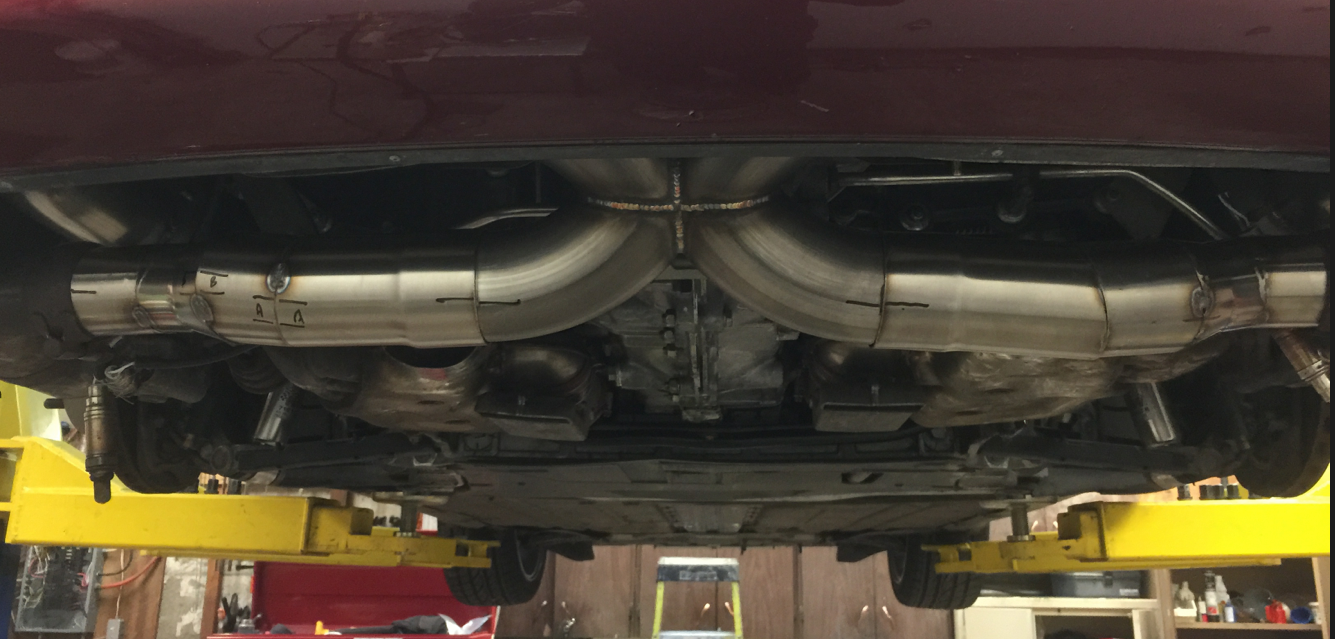
Next shot is around having the X-pipe in the correct spot. I wanted to make sure that bottom of the exhaust was no lower than the engine. I still have a low spot at the tail of the car, but its as high as I could get it and still put in Cats on the top pipes. Aligning took a LOT of time.
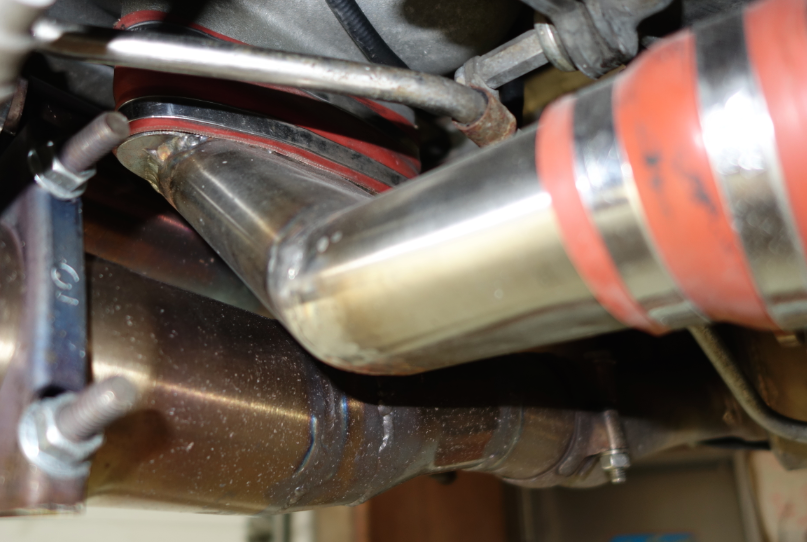
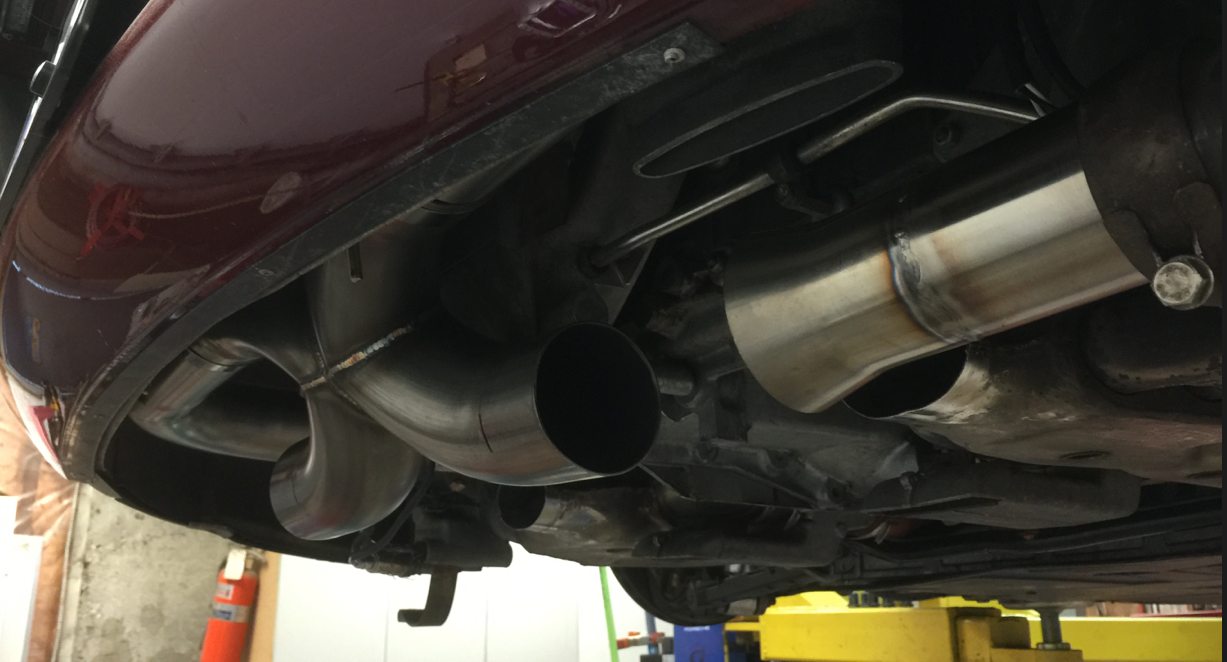
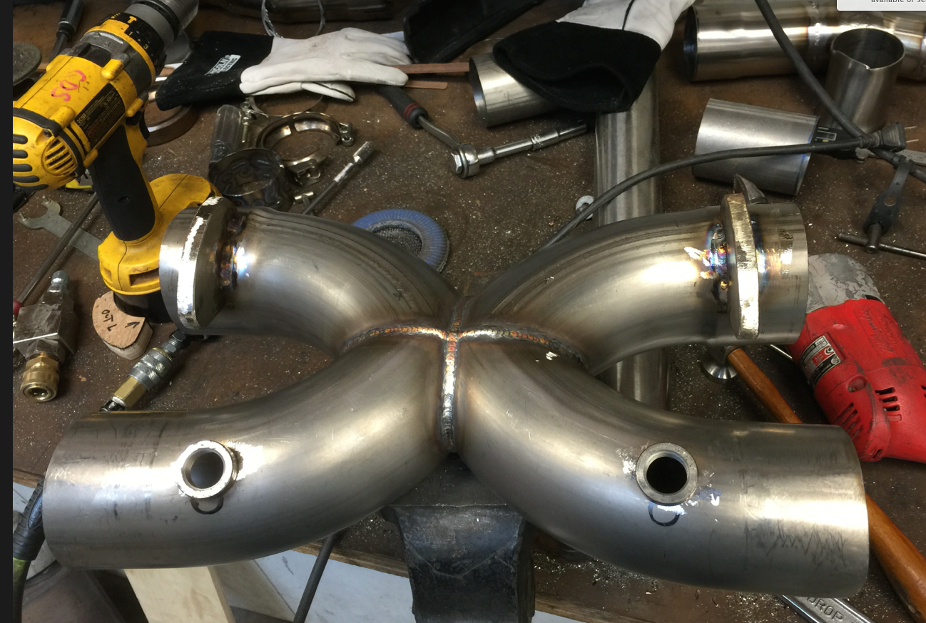
When I had the X-pipe in the correct spot, I then mounted the mufflers in their usual spots (making sure the tips were good) and fabricated backwards towards the X-pipe. Tricky angles, compounds angles that moved the pipes centerpoints in both X and Y space. I also needed to reduce the 3" pipe for now to 2.5" to match up with the mufflers, so in this shot you can clearly see the reduction section tacked in.
Now I roughed out the end to end circuit to the mufflers - and did small tacks to hold it all in place. To start, is used conventional slide joints so I could accommodate both rotations and back and forth movement.
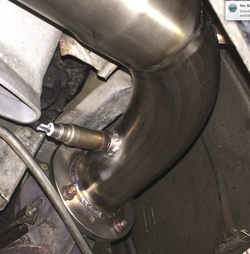
Ok, O2 sensors start to go in - here is the right hand side welded in, as well as the pipe welded to the turbo flange.
The X-pipe got a bit complex - it needed two O2 sensor bungs and a machined spacer to it could be attached to the existing exhaust hanger on the rear of the engine properly. Given the diameter change of the pipe, and its different positioning, I had to prototype the correct shape out of plywood, then cut it out of 1/4" SS plate, and weld them to the X-pipe. You can see the two mounts at the top of the X-pipe.
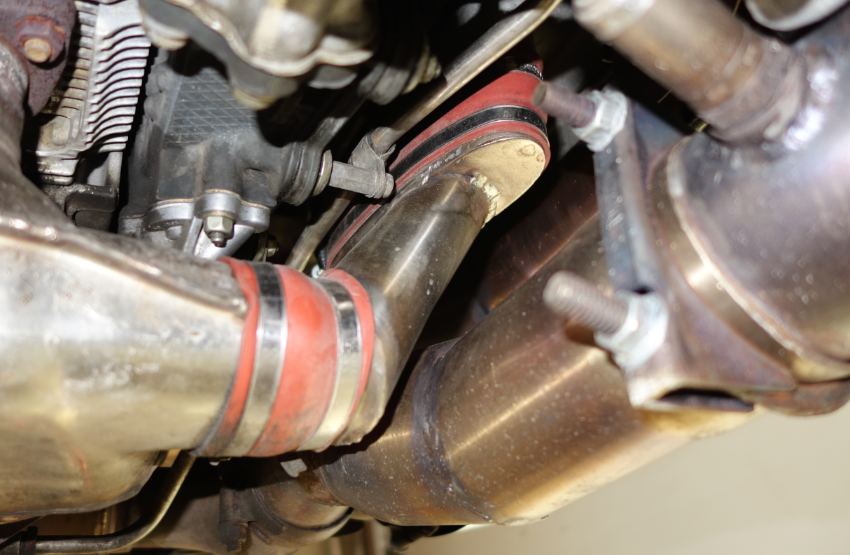
The X-pipe now goes back in and the O2 sensors mounted - the pipe has ovalized a bit, it can be corrected with some squeezing, but at times you need to do some bridging while TIG welding it... note the filler piece to mount the exhaust to the engine - fun stuff, and I like the crescent moon shape. It was a bitch to get in the right position though!
Ok, i positioned everything, then tacked it down and welded it up. SS can move a lot with heat distortion, so some careful welding was done - and I am no where near an expert on this stuff. Luckily I have had some training and bought a really good machine which helps.
So not I had a PROBLEM - no HEAT. I needed to get the hot air routed properly. On a stock system, it goes through a jacket around the exhaust, but I always thought that was pretty stupid, so i fabricated up tubing. Of course, round tubing would not fit, so I took some 2.5" stock and made up lengths of oval tubing (just SQUEEZE!), build custom connector flanges out of 16G flat SS stock, and welded it all together. (Man - that sounds easy - that was quite a few hours and definitely some trial and errors) - I love the way these look though!
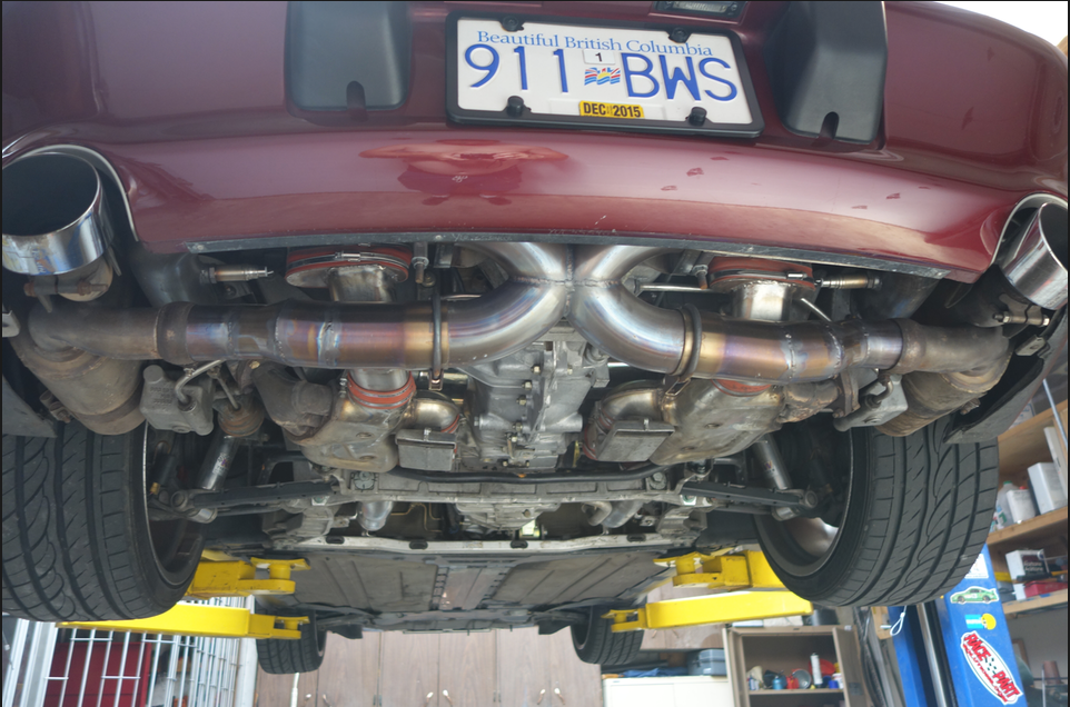
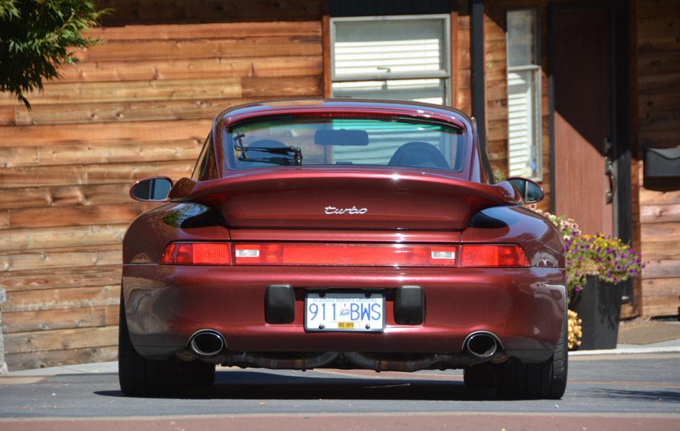
So it started to look like this after driving it for a month or so, including a DE and autox - note the nice patina on the SS. Not sure why anyone would polish a exhaust system, they will always end up looking like this.
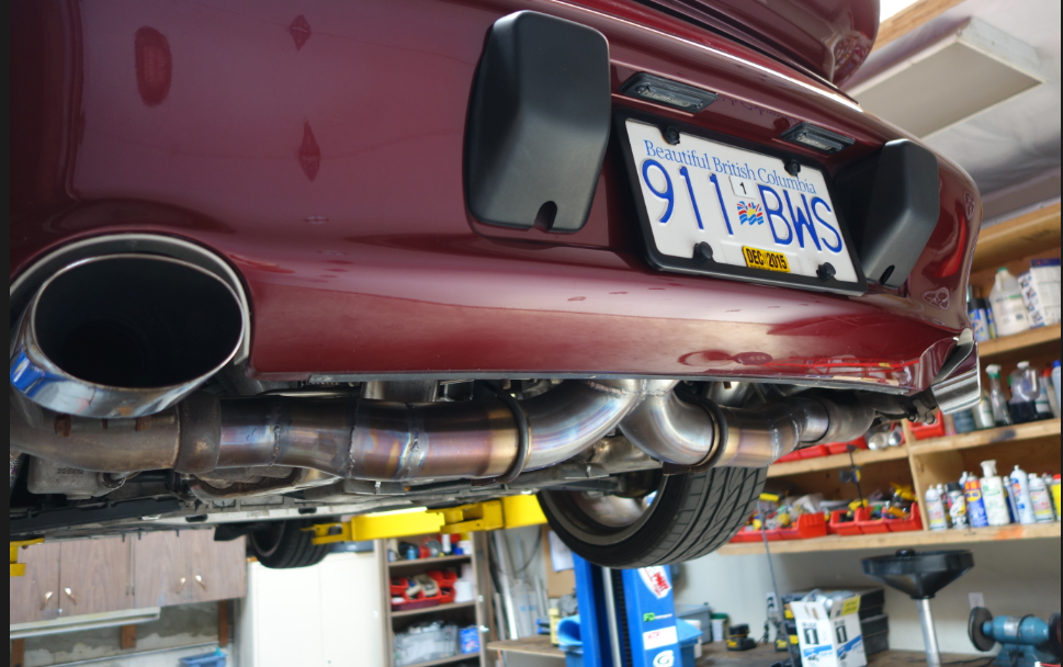
This picture does not do it justice - I have gotten comments on how the exhaust looks from the rear - the lower part of the X-pipe is definitely visible.
Conclusions:
- Exhaust building takes a lot of work, especially the first time.
- Expect some burns!!
- Is doable but does require metal working ability and some TIG welding skills. I would do a much better job a second time around.
The results? I am running this exhaust, no cats, plus modified mufflers (RSR's I believe - it's a long story and I am not quite sure - may have to cut them to find out) and the idle is now awesome. Its quite loud at startup, as Turbos are, but the tone is even and the putt-putt-putt is gone, and its quieter when warmed. Its quieter than full bypasses, about 2/3 between stock and bypasses, but a much more even tone. On throttle, the exhaust has a nice growl all the way up. If idling along or less gas, it runs nice and quiet. I will post a video, but that is never a good example of the real sound, you need to listen to an exhaust in person.
I now listen to the car as I stop at lights to heard that nice, rumbly idle - wonderful. It's not where close to say a GT3 RS with bypasses (that is a different league) but pretty good for a turbo.
The next steps? Possibly 3" all the way to the end, or a switchable exhaust. Not sure yet, but this one is so good I may not do anything..
Nice work Mike! I too like the idea of a separate heat tube. Well done.
We have had some online discussion in the past about the crossover hole size/shape in the "X". What shape and size did you end up using for the hole, or did you end up keeping the runs separate?
How does to perform compared to the Fabspeed set-up you had earlier, sound and performance wise?
Thank you very much for taking the time to update us!
All the tubing is 304SS from what I was told by my suppliers (and the tubing/parts were sourced from at least four different places) - however the section between the X- pipe and the mufflers (which has more discoloration) was from a local source here, and the pipes came pre-polished. It might be possible that that finish has reacted differently to the heat not sure. that was an industrial supplier, I will go check the tags to see if the allow designation is the same.
As for the X-pipe, the cross chamber is quite large, likely a bit large for tuned scavenging but that was not my goal - my goal was to mix the two sides effectively to obtain a better exhaust sound. The fabspeed system is well designed, but the port diameter is quite a bit smaller. In this case, the port is almost the cross section of two 3" pipes, while the Fabspeed system's X pipe is cast and uses 2.5" inlets, with port being the touch point between two 180 degree bends. I would say the port size is at least 2.5 to 3 times larger on my design.
As far as power goes, it seems livelier but again, no dyno results, and since its louder, it could be all in my head... . However, I was not expecting too much gain since I still restrict the piping down to 2.5" as it hits the mufflers. Ideally I should run 3" pipes all the way - maybe this winter, lol!
The fun part is that, since its my own frankenstein system, I can hack it up or modify it as I see fit - repairs too.
Looks like a major hack job. I'll take the whole system off your hands and you can make a better one, second time around :-)
Just let me know how much the postage will be and I'll have a check in the mail. :-)
Quality work and I am sure it was fun to explore the different designs/builds to get it just how you wanted. Exhaust building is no walk in the park!
I definitely appreciate what you guys do - it's really difficult to replicate a complex exhaust, keep the quality up, have no fitment issues outside of your control, and make money.
I just wish I had access to that nice CNC mandrel bender you have!
I was being facetious, wishing I was able to have the ability and tools to do such a nice job. Let me know when you wanna improve on your first attempt. I'll take your "experiment" and stick it on my car. :-)
Ref the performance side of it - do the exhaust gasses not 'crash' into each other head on? Sorry if that sounds a bit dumb!
Yes, probably some for sure. I suspect that a system like Fabspeed's might be able to squeeze a bit more performance because the port is smaller and right at the apex of the turn, so they will get scavaging between the pulses, or so is the theory.
However, this big X also allows flow across the pipe to the opposite exit which is almost a straight line, and the flow is already turning before it "collides". I wanted a bit of mixing to happen just because I am vain and wanted a nicer sound. I suspect the math and analysis of the dynamics of the flow through this system would drive you nuts, and I am an engineer (electrical though) and am used to a lot of math (or was before I lost my smarts! :_ ). I bet the flow results are non-obvious. I might even be screwing it all up!
Got some video shot, it sounds much better and truer, and am going to take a few flyby shots tonight and splice together a video. Stay posted - and it ain't gonna be professional, my TIG skills are much better than my video skills.... haha.


 07-14-2015, 09:18 PM
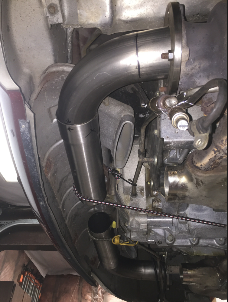


 I needed to get the hot air routed properly. On a stock system, it goes through a jacket around the exhaust, but I always thought that was pretty stupid, so i fabricated up tubing. Of course, round tubing would not fit, so I took some 2.5" stock and made up lengths of oval tubing (just SQUEEZE!), build custom connector flanges out of 16G flat SS stock, and welded it all together. (Man - that sounds easy - that was quite a few hours and definitely some trial and errors) - I love the way these look though!