Notices
993 Forum 1995-1998

Vacuum Diagram

Thread Tools
 
Search this Thread
 
Old 06-30-2014, 12:25 AM
  #1  
jstyer
Rennlist Member
Thread Starter
 
jstyer's Avatar
 
Join Date: Aug 2012
Location: Temple, TX
Posts: 1,063
Received 3 Likes on 3 Posts
Default Vacuum Diagram

Does anybody have a C2 vacuum diagram? Non-varioram would be best... But varioram would work as well.

Tore used to have one on his site, but the link no longer works.

Any help would be awesome.

Thanks again,

Justin
Old 06-30-2014, 03:18 AM
  #2  
ToreB
Rennlist Member
 
ToreB's Avatar
 
Join Date: Apr 2004
Location: Oslo, Norway
Posts: 2,415
Received 376 Likes on 238 Posts
Default

Hi, thanks for pointing out the broken link. It is now udated, see bottom of pagehere..
Cheers,
Tore
Old 06-30-2014, 10:12 AM
  #3  
jstyer
Rennlist Member
Thread Starter
 
jstyer's Avatar
 
Join Date: Aug 2012
Location: Temple, TX
Posts: 1,063
Received 3 Likes on 3 Posts
Default

Awesome tore. Thanks.

So looking at the diagram, the fresh air flap, and brakes are the only vacuum lines sent forward from the engine bay. Correct?
Old 06-30-2014, 02:50 PM
  #4  
ToreB
Rennlist Member
 
ToreB's Avatar
 
Join Date: Apr 2004
Location: Oslo, Norway
Posts: 2,415
Received 376 Likes on 238 Posts
Default

The diagram can be somewhat confusing. There's two vacuum operated ventilation flaps in the 993. Resirc flap (item 32) and the fresh air switch-over flap (3c) in the engine bay. The first is a known source for ventilation air flow problems, and the latter selects the air intake depending on if you put the car in reverse or not, and not very critical for ventilation functionality.

I have never looked at any vacuum hoses to the brakes, so I can't comment on that.

Cheers,
Tore
Old 06-30-2014, 04:02 PM
  #5  
Bill Verburg
Addict
Rennlist Member

 
Bill Verburg's Avatar
 
Join Date: May 2001
Posts: 12,254
Received 512 Likes on 352 Posts
Default

Originally Posted by jstyer
Awesome tore. Thanks.

So looking at the diagram, the fresh air flap, and brakes are the only vacuum lines sent forward from the engine bay. Correct?
Here's one I wrote some notes on.
Old 06-30-2014, 04:38 PM
  #6  
jstyer
Rennlist Member
Thread Starter
 
jstyer's Avatar
 
Join Date: Aug 2012
Location: Temple, TX
Posts: 1,063
Received 3 Likes on 3 Posts
Default

Great info guys.

I've already eliminated the functions related to the rear blower motor. I'm switching to manually controlled heater/ventilation functions, as well as a non assisted dual master cylinder brake setup. So it looks like I'll be able to completely remove the vacuum lines that go foward.

(With the exception of the fuel tank related lines)
Old 10-17-2016, 09:55 PM
  #7  
Ivan J
Racer
 
Ivan J's Avatar
 
Join Date: Oct 2015
Location: Anaheim Hills, CA
Posts: 400
Received 28 Likes on 22 Posts
Default

Originally Posted by Bill Verburg
Here's one I wrote some notes on.
Thanks to Bill Verburg for this diagram

The recirc flap for my HVAC system gets sucked closed by the airflow when I accelerate. I think that the inline check valve (the upper instance of #8 in the diagram) might have failed. Can anyone show me where this check valve is located?

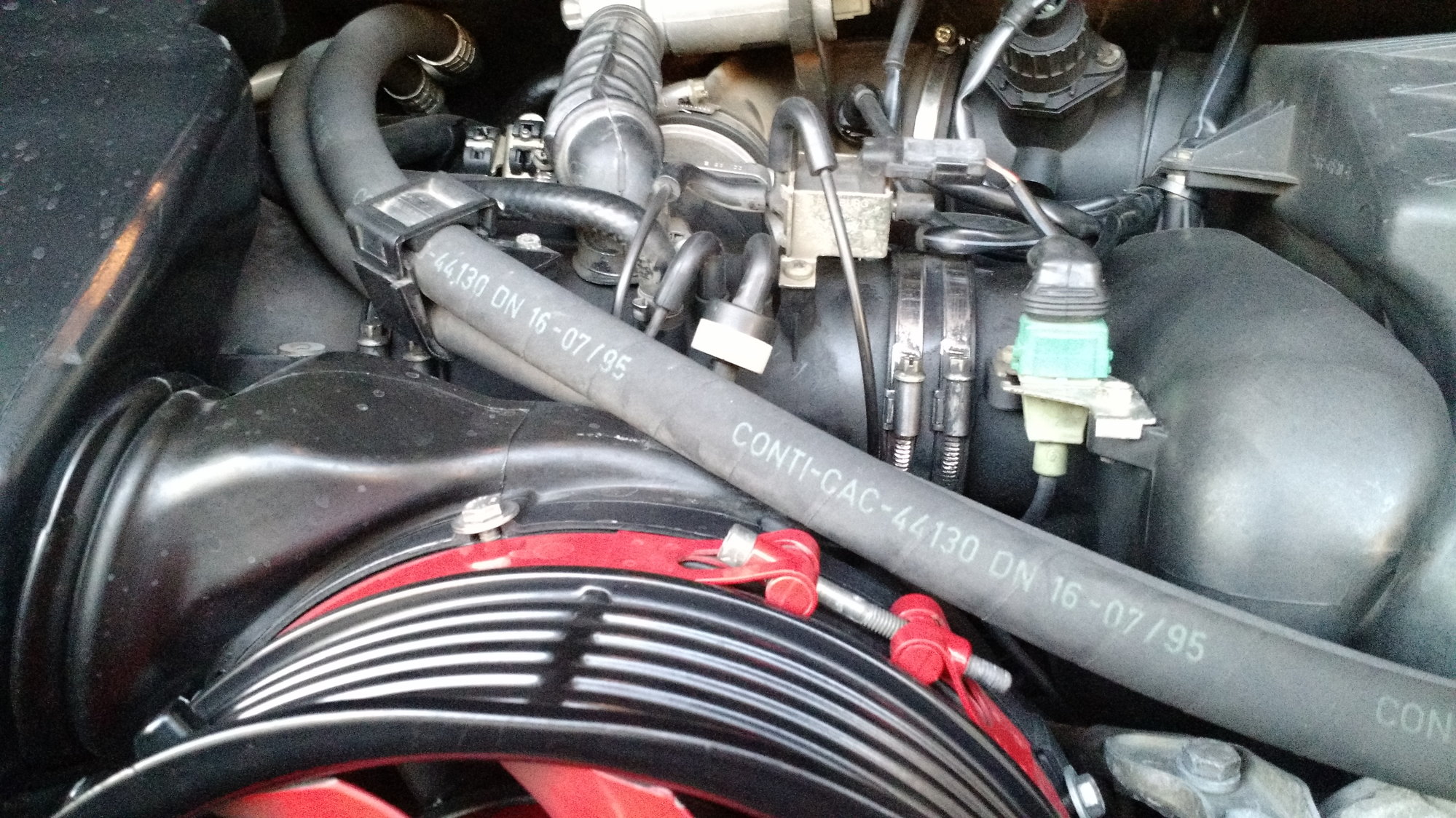
On a related note, there is a black and white plastic valve that connects to the intake manifold, which I think is a check valve. It is located in the center of the photo below. Mine seems to be failed closed, I can't blow air through it in either direction. Which valve in the diagram does this correspond to?


Quick Reply: Vacuum Diagram


All times are GMT -3. The time now is 07:55 AM.