When you click on links to various merchants on this site and make a purchase, this can result in this site earning a commission. Affiliate programs and affiliations include, but are not limited to, the eBay Partner Network.
Since it is now hot in Texas, i noticed the coolant gauge rising and the warning light coming on. With Roger's help, he and some rennlist posts led me to this check list.
- no fans with turned on Ac and ensured ac button on
- no fans with intake temp wires shorted and hood button pressed
- shorted pins 4&8 and confirmed 12Vs at driver's side fan connection
Power for the fans comes through two of the smaller wires that connect at the battery positive post. VERIFY that the connections there are clean and tight.
From the battery, power is fed to the two fan fuses individually. IIRC these are 28 and 29 in the central-electrics panel, at the passenger's feet under the carpet. VERIFY, using a DMM with needle probe, that you have battery voltage on both sides of both fuses with the fuses installed, and the fans should be running (intake temp switch jumpered). There's a tiny hole over each fuse pin to use with the needle probe to test with them in circuit.
VERIFY that the fuse holders are not melted. Weak connections and high fan current draw have been known to cause enough heat to melt the plastic fuse-holder sections of the panel.
You can VERIFY fan functionality with a couple jumper wires connected to the fan motor connections. Ground one, touch the other briefly to the jump post terminal, under the plastic cover on the forward right (passenger side on US cars...) fender wall area. The fan should run at full speed.
There is no easy way to test the output of the fan "final stages" module under load.
The workshop manuals have a good fan system troubleshooting guide, once you have established that you have sufficient power available to the controllers and the the fan motors themselves are functional.
One fan failing is distinctly possible if they are originals but two simultaneously?- sounds a bit like double jeopardy to me. It is possible you may have had one fail for some time and not know it but both gone you sure will.
You might check for voltage at the other fan before doing anything else but if there is voltage at a fan and it does not spin it looks rather ominous. You can always test the fans by a direct jump from the hot post- just make sure you get the polarity correct or you will have a welding machine.
I also wonder if it is possible for the control element stage to pass voltage but little to no current such that the fans do not rotate?
I'll add that it's important to test for fan voltage UNDER LOAD. The fan circuits are high-current supplies. Resistance that won't show up testing voltage with a meter at no load can drop available voltage to almost none when the fan motor loads are applied. Hence my suggestion above to test at the fuses with the fuses installed and motors trying to run. If you are testing with a meter at the controller or harness end with no load, your readings might steer you to believe that there's sufficient current flow available. When there isn't.
- Checked voltage at fuses 28 & 29 on both sides each and got 12V.
- CE panel looks clean and un-melted from the front, should I remove and check the back?
- Haven't checked fan functionality yet. Need to get some long enough jumpers to the jump terminal
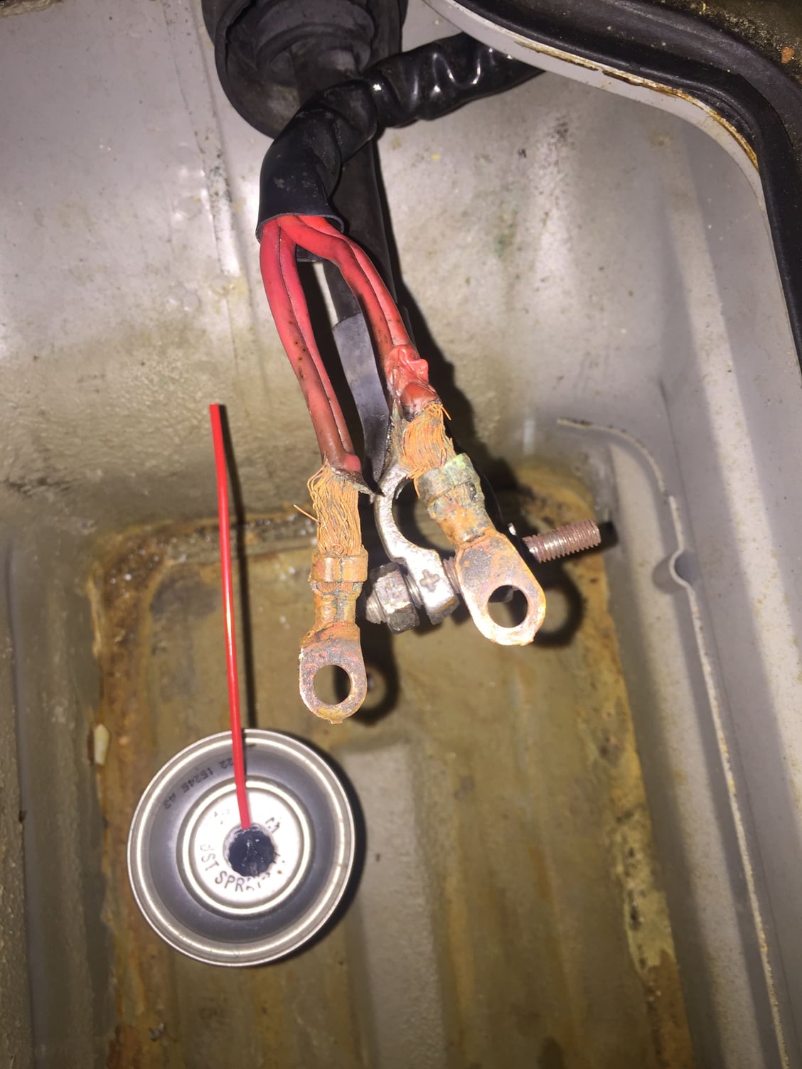
- I cleaned the terminals when I first got the car, but I may not have cleaned enough. Looks like the the leads at the terminal could use a refreshing (see pic). Should I cut off the old ends until clean cooper is showing and attach some new leads?
- Checked voltage at fuses 28 & 29 on both sides each and got 12V.
- CE panel looks clean and un-melted from the front, should I remove and check the back?
- Haven't checked fan functionality yet. Need to get some long enough jumpers to the jump terminal
- I cleaned the terminals when I first got the car, but I may not have cleaned enough. Looks like the the leads at the terminal could use a refreshing (see pic). Should I cut off the old ends until clean cooper is showing and attach some new leads?
I'd start there, with new lugs and back to good wire. Add good shrink sleeve over the connections once they are proven mechanically and electrically sound.
When you were checking voltage at 28 and 29, did you have the fans trying to run? Without motor load on the end of the circuit, the high impedance of the typical meter isn't enough load to on its own to test for resistance and resultant voltage drop under load. One tiny strand is enough to satisfy the meter, while a fan motor load would drop voltage to almost none.
Make Sure you have a good vent tube attached to the battery vapor vent, directing the fumes out of the battery compartment. Those connections and the wires are pretty ugly. Copper sulfate where pure copper used to be! The other small wires are fuel pump, injection, ignition. Stuff you probably want working well.
Those wires look pretty grotty and as you can see it looks as though some of the sheath has melted.
If splicing the cables is a bit intimidating for you, you can try a little trick I use to better understand the condition of the cables/clean the conductor up a bit locally. Take a cup of vinegar, add a table spoon of salt and mix it. Dunk the ends in this mix for 20 minutes and then take a look at the copper conductors. This is particularly useful if you are going to splice with a cold crimp should you have difficulty finding clean cable. You can also neutralise the acid solution with some baking soda solution or just give the cable a good rinse with water. If nothing else I would put some new shrink sleeve over those cables
Another thing you might consider if your wiring condition is not too clever is to fit a direct power supply to the fans from the hot post via an in-line fuse and a relay. SPAL do a very nice $40 kit for this and JEGS do one even cheaper [$26] but no idea of their quality. Then the fan signal is used as a relay trigger so voltage drop not an issue. With judicious installation you would hardly notice the mods.
This does not solve any existing problem you may have in the existing fan circuits should they exist. If you have serious grief with the fan control system SPAL also do a programmable controller wiring kit wherein you fit a sensor into the cooling system directly. I was once told by a notable 928 personality some years ago that the fan system even when working correctly puts a reduced voltage on the fans for some reason. I cannot verify this comment but for the fans to work optimally they need a good strong power supply given the current they draw.
If one needed to do such the voltage drop will be minimised due to the short cable run length so a cable a little smaller than the stock ones would probably suffice. Needless to say I would prefer the stock system working as intended.
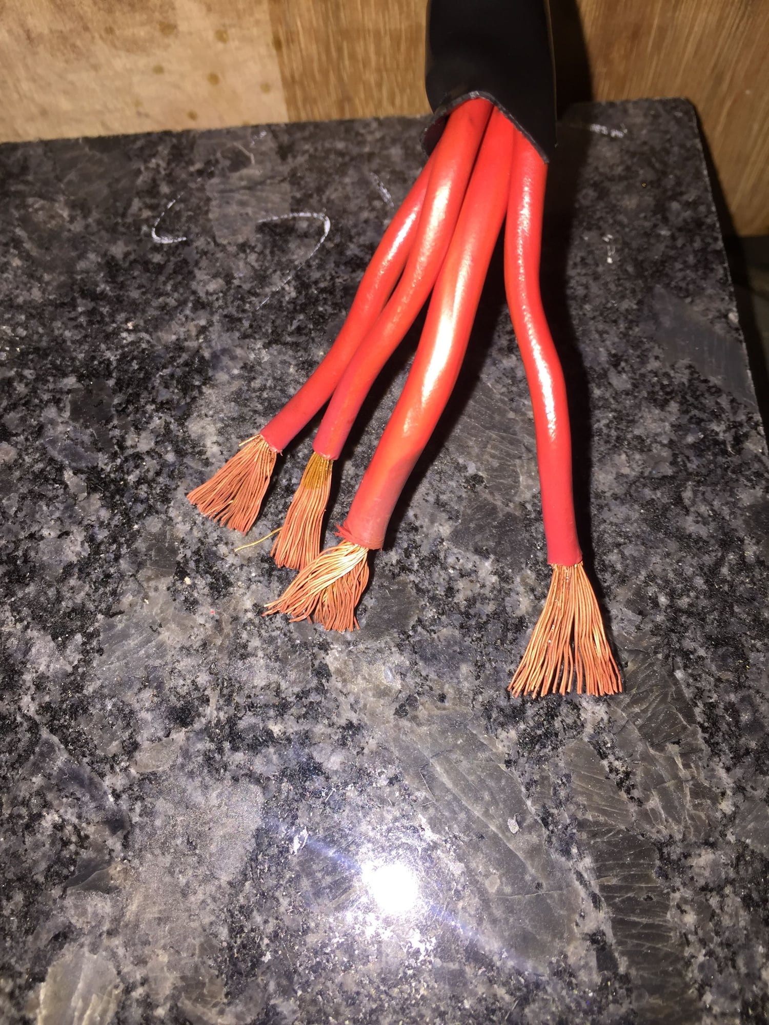
I will definitely keep you guys in loop. I decided to try and clean up the connections. Cut the leads off and re-stripped wires. I figured the copper would be cleaner. Are these still good to re-crimp?
We were side tracked today. Our creek rose 4' or so and was close to the house. It is down now, 10" or so, but not sitting easy until water is in its banks.
Ok, I followed Mr Merlin's advice and cleaned the wires in vinegar and salt for 20min.
Then bought new copper ends, crimped and soldered the connections.
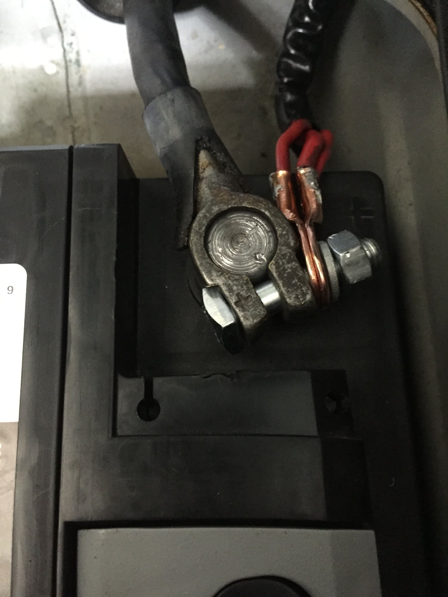
Once I reconnected everything, I started the car, turned on AC, and FANS. YES!!! I really appreciate all the help from Roger, Fred, Dr Bob, and MrMerlin. You guys rock. Michael
Glad you are surviving the forty-days-and-forty-nights of rain packed into these few days. And glad your fans are working with minimum fuss.
Thoughts:
-- Slide some shrink tube over your connections. It can help keep any corrosive fumes from getting further up into the jacket.
-- You'll want to re-work the stack arrangement on the battery bolt. Might be as easy as a couple small washers between the clamp and your lugs so they are square to the bolt. Passing current there relies on surface contact.
-- Last but not least, once all is secure mechanically and electrically, coat the whole post and connections there with Vaseline for more corrosion protection.
Dr. Bob, Will do. I figured I would try to find some type of accessory bolt or what Bob S suggested. I noticed there was a hole (vent tube size) near the negative terminal. Should I drill another hole near the positive terminal?
Bob S. That is a pretty awesome. I may have to get one of those too.
I would NOT drill another hole if at all possible. The metal edge/hole would be un-protected, therefore subject to corrosion from sources both inside and out. Plus I just don't drill "extra" holes in future-collectible cars; call it a passion.
The small 1/4" OD plastic tubing I used fit nicely through the existing rubber gaitor/bellows/grommet where the large positive cable passes forward out of the battery box. I just cut the end at an angle, and gently pushed it through next to the cable itself. Painless.

 05-27-2016, 01:58 PM