

PWM dimmer for instrument backlighting after upgrading to LEDs


 12-04-2012, 01:02 PM
#63
I have a variety of lights, some old, some new.
The gauges and warning lights have been converted to LEDs.
The lighting in the pod switches are stock as are those in the center console.
Does your PWM device work with the older (stock) lighting?
Thanks for your development efforts!
The gauges and warning lights have been converted to LEDs.
The lighting in the pod switches are stock as are those in the center console.
Does your PWM device work with the older (stock) lighting?
Thanks for your development efforts!
12-04-2012, 02:48 PM
#64
Addict
Rennlist Member
Rennlist Member
Thread Starter
Long answer: It'll drive up to 3 A; that's enough for about 36 W of bulbs (LED and/or incandescent) at 12 V. Even if you haven't replaced any of the incandescent bulbs (controlled by the dimmer) with LEDs, you'll be under 36 W. I could crank the maximum driving current for the dimmer module up a bit; I've got it software configured to limit it to about 3 A right now: (1) for output short-circuit detection/protection, and (2) because it keeps thermal management issues inside the dimmer module to a minimum.
 12-04-2012, 08:59 PM
#66
Archive Gatekeeper
Rennlist Member
Rennlist Member
Two assembled boxes here, please. Fewer electrons will be spilled if I don't try to assemble them myself....
12-04-2012, 09:28 PM
#67
Addict
Rennlist Member
Rennlist Member
Thread Starter
I'll be contacting you guys once I've got stuff ready to go (it's getting close...  ).
).
PCBs arive tomorrow AM. But... I still need to get the enclosures put together and, of course, make sure the PCBs when populated actually work.
Tony... you can help me with something: do you know what kind of dimmer rheostat your '88 uses? And I'd really be interested in anyone with an '89 answering this same question:
Does it look like this (a 928.613.121.01, thumb wheel is about 5.0 mm thick)?

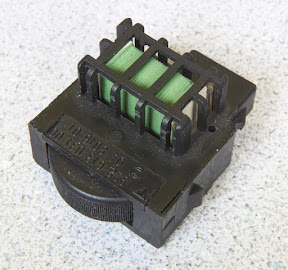
or this (a 928.613.031.00, thumb wheel is about 9.4 mm thick)?
I'd really like to know this because I've seen conflicting information on when the rheostat changed. Based on one source (dC Automotive's on-line parts), the former one was used until '88. 928 Int'l and Auto Atlanta says the new one was '90 on. 928 Specialists shows the former one being used through '89. This seems rather strange to me, because I would have thought that the change would have occurred with S4s in '87, but maybe not. Based on the available information, though, I'm guessing that the former one was used until '89 and the latter one was used '90 on (that's pretty consistent with the above-mentioned sources).
I'm just trying to sort this out, because I might ship slightly different connection (wiring hook-up) kits based on the dimmer rheostats in use. The former rheostat has standard male blade-style terminals that will connect to wires terminated with female blade-style terminals. The latter rheostats use a weird two-pole connector that I'll probably never be able to track down, so I'll have an alternative connection recommendation.
).PCBs arive tomorrow AM.
But... I still need to get the enclosures put together and, of course, make sure the PCBs when populated actually work. Tony... you can help me with something: do you know what kind of dimmer rheostat your '88 uses? And I'd really be interested in anyone with an '89 answering this same question:
Does it look like this (a 928.613.121.01, thumb wheel is about 5.0 mm thick)?
or this (a 928.613.031.00, thumb wheel is about 9.4 mm thick)?

I'd really like to know this because I've seen conflicting information on when the rheostat changed. Based on one source (dC Automotive's on-line parts), the former one was used until '88. 928 Int'l and Auto Atlanta says the new one was '90 on. 928 Specialists shows the former one being used through '89. This seems rather strange to me, because I would have thought that the change would have occurred with S4s in '87, but maybe not. Based on the available information, though, I'm guessing that the former one was used until '89 and the latter one was used '90 on (that's pretty consistent with the above-mentioned sources).
I'm just trying to sort this out, because I might ship slightly different connection (wiring hook-up) kits based on the dimmer rheostats in use. The former rheostat has standard male blade-style terminals that will connect to wires terminated with female blade-style terminals. The latter rheostats use a weird two-pole connector that I'll probably never be able to track down, so I'll have an alternative connection recommendation.
12-04-2012, 09:33 PM
#68
Rennlist Member
I'll be contacting you guys once I've got stuff ready to go (it's getting close... ).
PCBs arive tomorrow AM. But... I still need to get the enclosures put together and, of course, make sure the PCBs when populated actually work.
Tony... you can help me with something: do you know what kind of dimmer rheostat your '88 uses? And I'd really be interested in anyone with an '89 answering this same question:
Does it look like this (a 928.613.121.01, thumb wheel is about 5.0 mm thick)?
or this (a 928.613.031.00, thumb wheel is about 9.4 mm thick)?
I'd really like to know this because I've seen conflicting information on when the rheostat changed. Based on one source (dC Automotive's on-line parts), the former one was used until '88. 928 Int'l and Auto Atlanta says the new one was '90 on. 928 Specialists shows the former one being used through '89. This seems rather strange to me, because I would have thought that the change would have occurred with S4s in '87, but maybe not. Based on the available information, though, I'm guessing that the former one was used until '89 and the latter one was used '90 on (that's pretty consistent with the above-mentioned sources).
I'm just trying to sort this out, because I might ship slightly different connection (wiring hook-up) kits based on the dimmer rheostats in use (the former rheostat has standard male blade-style terminals that will connect to wires terminated with female blade-style terminals. The latter rheostats use a weird two-pole connector that I'll probably never be able to track down, so I'll have an alternative connection recommendation.
).PCBs arive tomorrow AM.
But... I still need to get the enclosures put together and, of course, make sure the PCBs when populated actually work. Tony... you can help me with something: do you know what kind of dimmer rheostat your '88 uses? And I'd really be interested in anyone with an '89 answering this same question:
Does it look like this (a 928.613.121.01, thumb wheel is about 5.0 mm thick)?
or this (a 928.613.031.00, thumb wheel is about 9.4 mm thick)?
I'd really like to know this because I've seen conflicting information on when the rheostat changed. Based on one source (dC Automotive's on-line parts), the former one was used until '88. 928 Int'l and Auto Atlanta says the new one was '90 on. 928 Specialists shows the former one being used through '89. This seems rather strange to me, because I would have thought that the change would have occurred with S4s in '87, but maybe not. Based on the available information, though, I'm guessing that the former one was used until '89 and the latter one was used '90 on (that's pretty consistent with the above-mentioned sources).
I'm just trying to sort this out, because I might ship slightly different connection (wiring hook-up) kits based on the dimmer rheostats in use (the former rheostat has standard male blade-style terminals that will connect to wires terminated with female blade-style terminals. The latter rheostats use a weird two-pole connector that I'll probably never be able to track down, so I'll have an alternative connection recommendation.
My 88 S4 is the thin wheel sir.
And yes, I would still like one completed box please!
My OEM rheostat is fubar anyhows.
12-05-2012, 11:27 AM
#70
Electron Wrangler
Lifetime Rennlist
Member
Lifetime Rennlist
Member
Yes - Digi-dash changed the mounting method (modular vs. direct) & connector - so its highly likely thats when the change was made.
Alan
Alan
12-05-2012, 06:25 PM
#71
Nordschleife Master
Hmm.. I thought my '89 has the thinner kind in the top picture, but I may be confusing it with my 87.
Back in a minute - gonna go snap a pic
edit: Yep - definitely the thin type in '89 (with digital dash). I'm guessing the change was in 90 with the other major wiring changes like airbags, window switch controllers etc.
edit2: This could of course be some bizarre RHD anomaly Pics from a LHD car to cross-check would be good.
Back in a minute - gonna go snap a pic
edit: Yep - definitely the thin type in '89 (with digital dash). I'm guessing the change was in 90 with the other major wiring changes like airbags, window switch controllers etc.
edit2: This could of course be some bizarre RHD anomaly
Pics from a LHD car to cross-check would be good.
12-05-2012, 11:02 PM
#72
Addict
Rennlist Member
Rennlist Member
Thread Starter
OK, thanks a lot, guys, for that info.
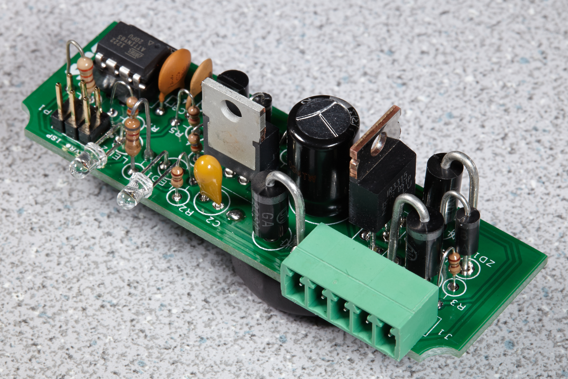
Good news: I got the PCBs in today. Populated one. Took longer than I thought it would (there are 74 solder joints, in case you were wondering), but I was taking notes as I went and double checking a lot of stuff. What's cool, though, is that it worked the first time I powered it up (after I programmed the microcontroller)!. Makes me happy.
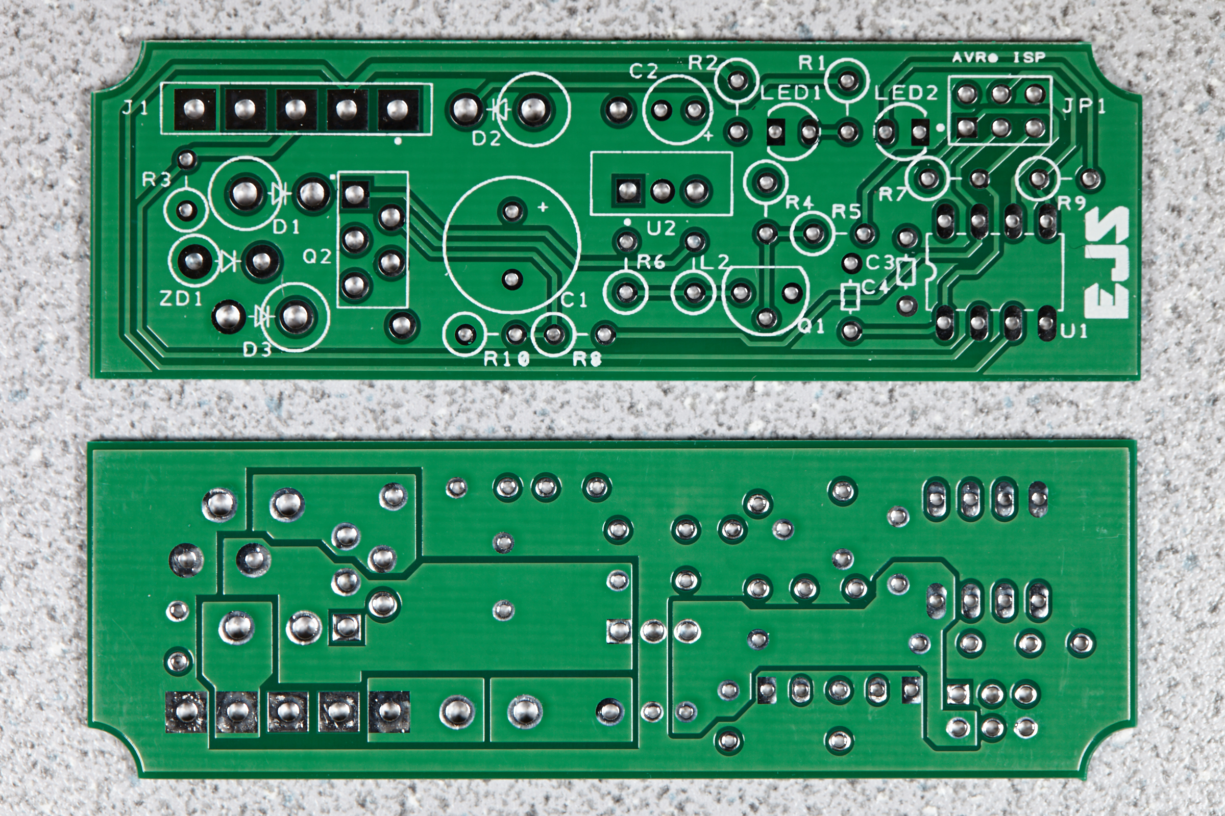
The only slightly bad news is that the bottom of the PCB was supposed to be silkscreened (but wasn't due to a mistake by the PCB service), too, so the stuff on the back isn't properly labeled as I designed it. It doesn't really affect functionality, but it bugs me ('cuz I'm a perfectionist). I'll probably order another batch of PCBs within a couple of days. If you compare the bottom side of the PCBs to the renderings I posted earlier, you'll see there's no white silkscreened stuff on the back.
Some annotated photos:
The top and bottom sides of the PCBs. Top side is A-OK. Bottom side is missing the silkscreen.

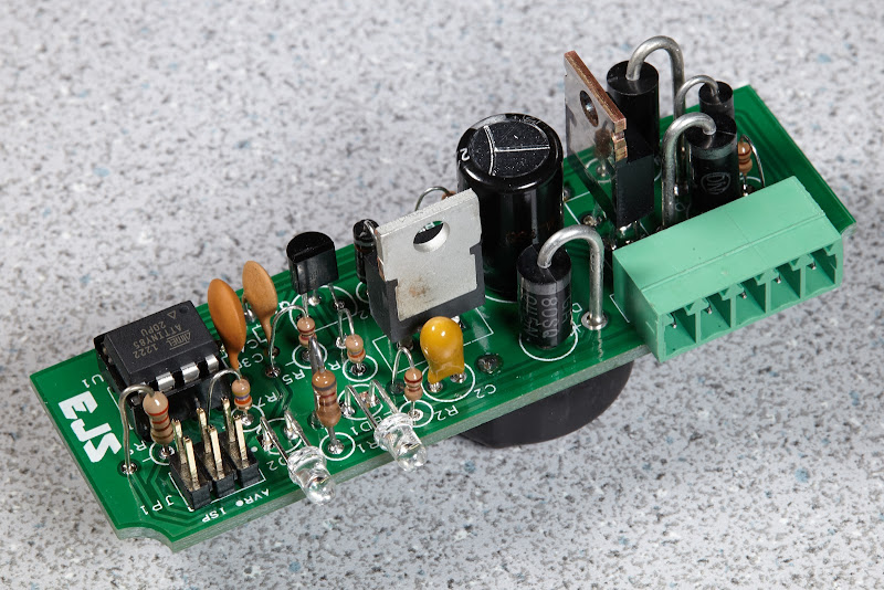
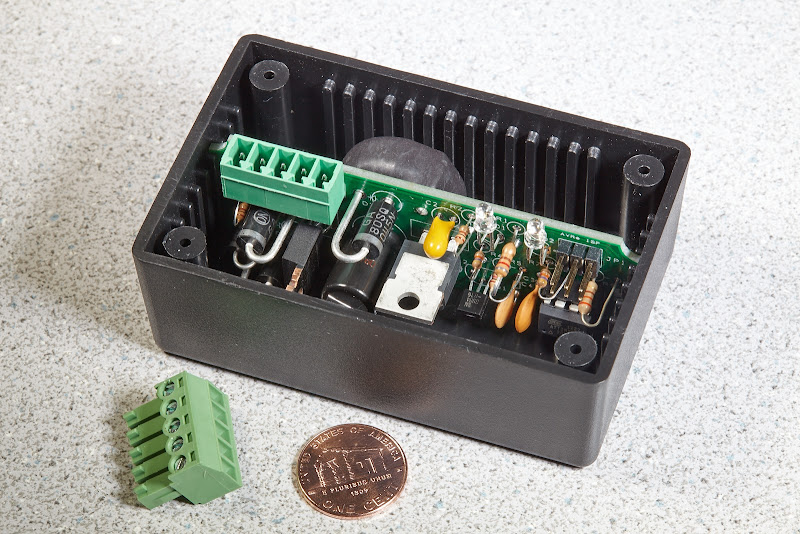
Fully populated board (multiple angles, because I like taking photos):
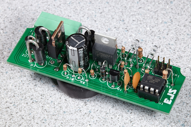


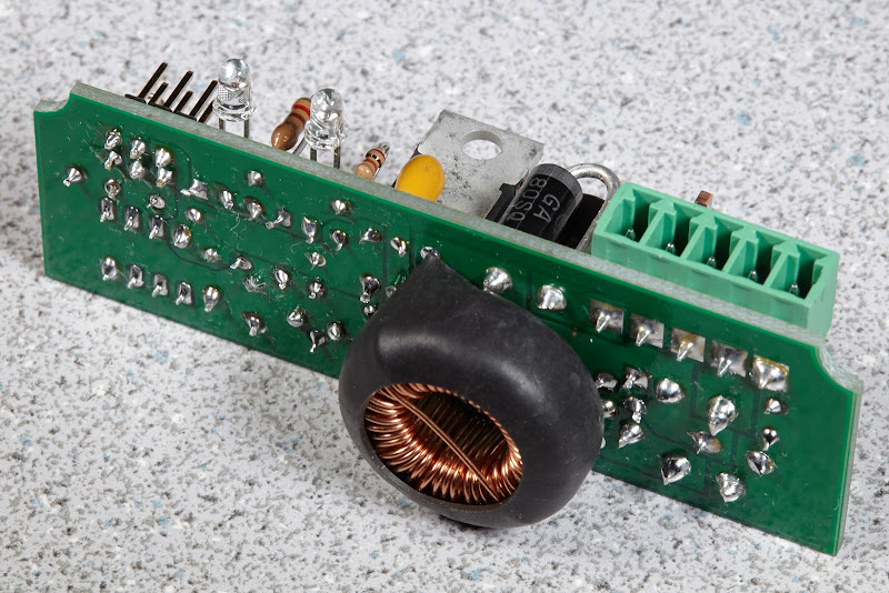
One thing that really worked out great is that these PCBs fit perfectly in the enclosure. Just perfect size; a little effort to slide in, but tight enough that there's no rattle.
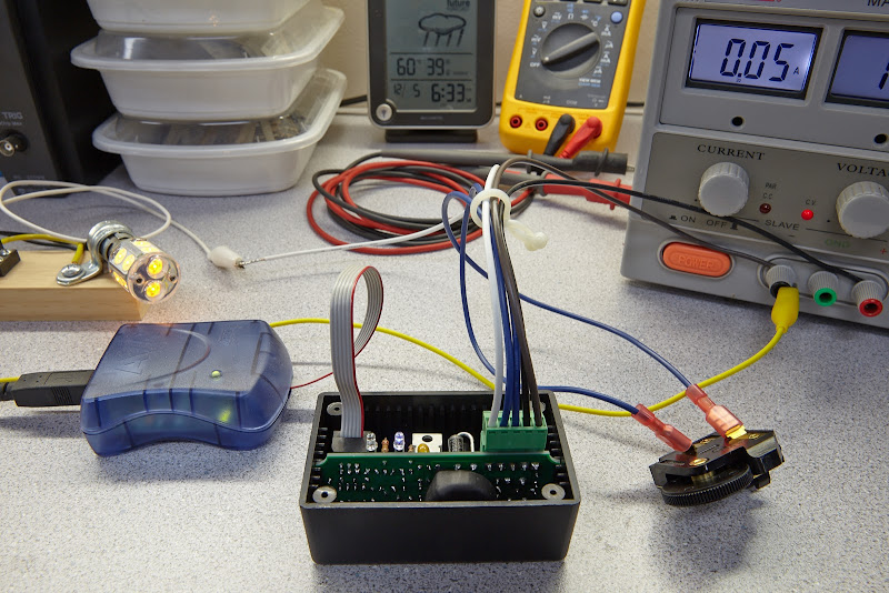
OK, for you guys who requested DIY kits, I can tell you that this is what I used to assemble unit serial #1:

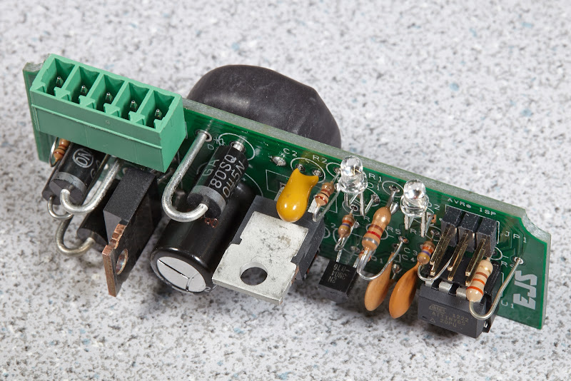
Successful power-up and programming of unit serial #1 (the gray ribbon cable is for in-system programming of the microcontroller; the five wires on the green connector are what you'll be using in your car):

Close-up of above. In case you're wondering, the wires on the green connector are (from left to right):
Good news: I got the PCBs in today. Populated one. Took longer than I thought it would (there are 74 solder joints, in case you were wondering), but I was taking notes as I went and double checking a lot of stuff. What's cool, though, is that it worked the first time I powered it up (after I programmed the microcontroller)!. Makes me happy.
The only slightly bad news is that the bottom of the PCB was supposed to be silkscreened (but wasn't due to a mistake by the PCB service), too, so the stuff on the back isn't properly labeled as I designed it. It doesn't really affect functionality, but it bugs me ('cuz I'm a perfectionist). I'll probably order another batch of PCBs within a couple of days. If you compare the bottom side of the PCBs to the renderings I posted earlier, you'll see there's no white silkscreened stuff on the back.
Some annotated photos:
The top and bottom sides of the PCBs. Top side is A-OK. Bottom side is missing the silkscreen.
Fully populated board (multiple angles, because I like taking photos
):


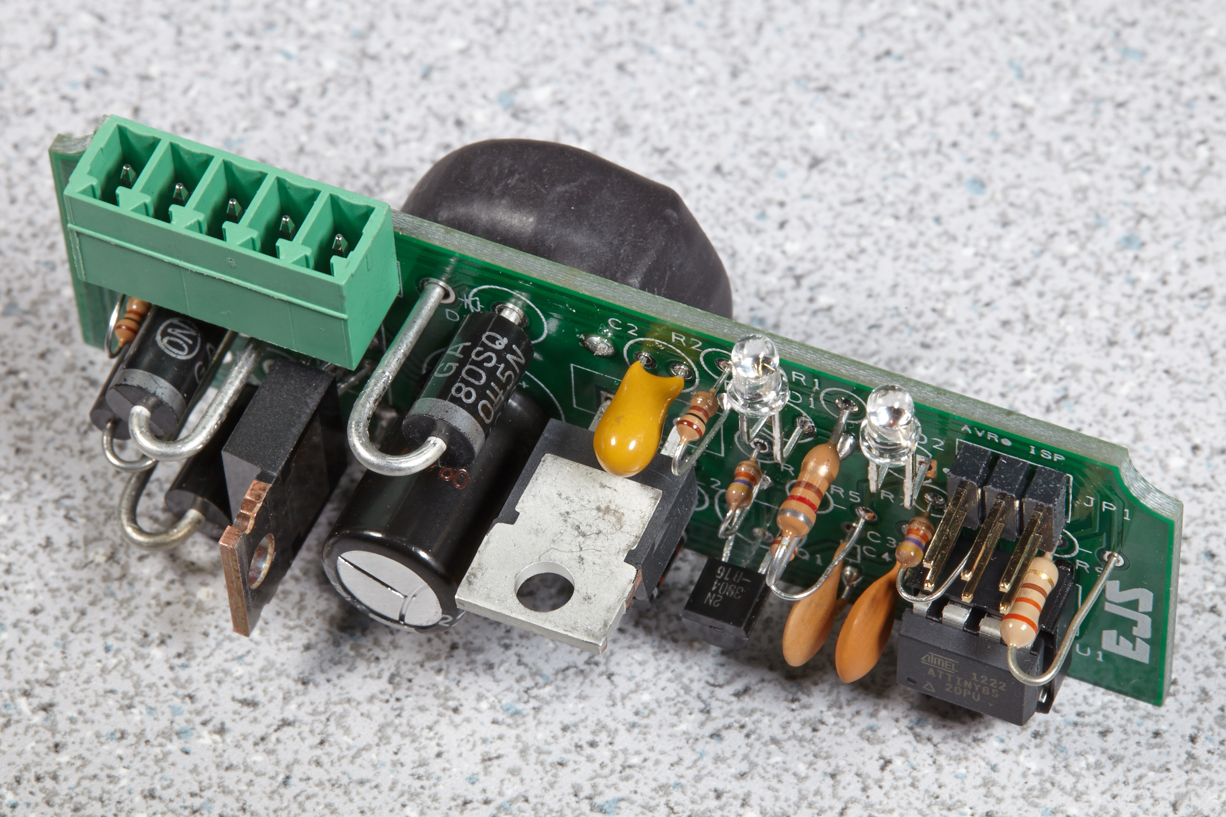

One thing that really worked out great is that these PCBs fit perfectly in the enclosure. Just perfect size; a little effort to slide in, but tight enough that there's no rattle.

OK, for you guys who requested DIY kits, I can tell you that this is what I used to assemble unit serial #1:

Successful power-up and programming of unit serial #1 (the gray ribbon cable is for in-system programming of the microcontroller; the five wires on the green connector are what you'll be using in your car):
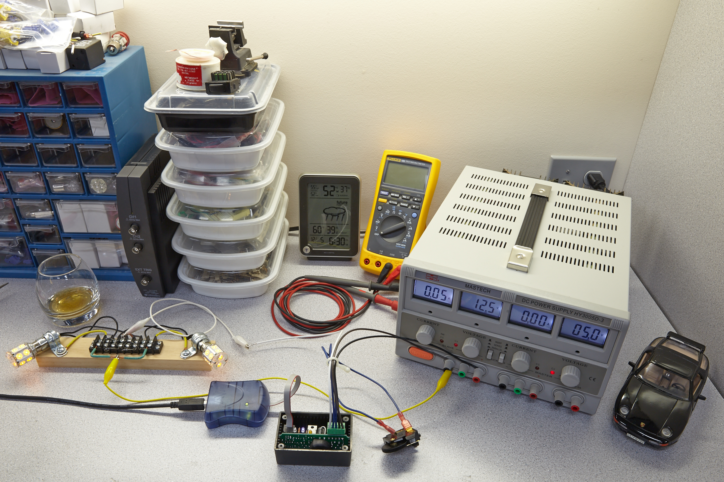
Close-up of above. In case you're wondering, the wires on the green connector are (from left to right):
- (white wire in photo; will be BK/BL when installed) output to instrumentation lighting (it will connect to one of the wires originally connected to your rheostat)
- (blue wire) rheostat A (doesn't matter which terminal on rheostat)
- (blue wire) rheostat B (doesn't matter which terminal on rheostat)
- (black wire) power in (it will connect to one of the wires originally connect to your rheostat)
- (brown wire) ground (you'll have to connect this to any chassis ground point)

Last edited by Ed Scherer; 12-18-2012 at 01:48 PM.
12-05-2012, 11:41 PM
#74
Addict
Rennlist Member
Rennlist Member
Thread Starter
OK, now that I think I'm pretty much past the PCBs, I need to turn my attention to finalizing the enclosures (not the point of this message) and ... making sure I get the control orientation correct (I can do this in software).
On my '90 with the "thicker thumbwheel" 928.613.031.00 that looks like this, I believe mine is oriented as shown (with that "cage part" up):
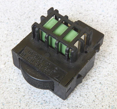
And to increase the illumination level, I move my thumb to the right, turning the thumbwheel counterclockwise (anticlockwise, for some of you) when viewed from above. That's the way mine works (and note that mine is using a very early prototype of this PWM dimmer). For you '90+ folks, is that the way yours works? I suspect I might have reversed the operation of the control when I did the software for the prototype dimmer that's in my car, but the way it works now on mine seems correct to me.
And for the '77-'89 folks, is your dimmer rheostat oriented like Hilton showed in the first (left-hand side) photo in post #71, with the "resistance coil" up and the terminals down? As you move your thumb to the right, then, wouldn't the illumination level actually decrease? Is this the way you want it?

On my '90 with the "thicker thumbwheel" 928.613.031.00 that looks like this, I believe mine is oriented as shown (with that "cage part" up):
And to increase the illumination level, I move my thumb to the right, turning the thumbwheel counterclockwise (anticlockwise, for some of you
) when viewed from above. That's the way mine works (and note that mine is using a very early prototype of this PWM dimmer). For you '90+ folks, is that the way yours works? I suspect I might have reversed the operation of the control when I did the software for the prototype dimmer that's in my car, but the way it works now on mine seems correct to me.And for the '77-'89 folks, is your dimmer rheostat oriented like Hilton showed in the first (left-hand side) photo in post #71, with the "resistance coil" up and the terminals down? As you move your thumb to the right, then, wouldn't the illumination level actually decrease? Is this the way you want it?
12-05-2012, 11:44 PM
#75
Addict
Rennlist Member
Rennlist Member
Thread Starter


Thanks for your help, though; feel free to PM me any alternatives I might want to check out.