When you click on links to various merchants on this site and make a purchase, this can result in this site earning a commission. Affiliate programs and affiliations include, but are not limited to, the eBay Partner Network.
Tech post: A look into the DME fuel injection circuit
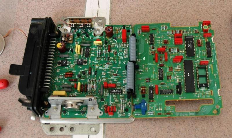
In the past I have covered the ISV circuit, its typical failure mode, and the uber cheap repair. Today I finally opened up the dead DME from my 86 N/A and after poking around, thought I would share some information concerning the injection driver circuit which applies to all 8 valve NA DME. Basically, the driver consists of an RBDT93 NPN power transistor which is used to pulse a ground to the injectors to fire them, along with an OF622 diode to handle the flyback current. There is also a 14 DIP integrated circuit labled 0127 which is a peak and hold type driver which senses current and works in conjunction with the RBDT93 to pulse the injectors. The typical failure of an otherwise perfectly functioning DME that does not provide an injector pulse is the failure of the 0127 IC, or less commonly the RBDT93. These are no loner available, but the 2N5984 should be a good substitute for the RBDT93. The OF622 diode is also no longer available, the MUR1540 is a decent option that will work, and they are available for ~1 dollar. The closest thing I've found to replace the peak and hold IC is the IR2110. The LM1949 is actually a MUCH better choice, but I don't know if its available in the same case as the 0127. Also for clarification, here are some pictures.
#11 is the RBDT93, #16 is the peak and hold IC, and #10 is the diode. Hope this helps some people. #8 are the ISV ON588 drivers that I discussed in another write up.
Thanks guys, Paulyy I agree its a bit hard to see, when I was looking at it earlier I had it blown way up, I'll edit it and bold/make the font red. I'm also going to be experimenting with the dead DME, I'll be ordering the 3 components I mentioned and see if I can actually fix this. The ISV fix is simple and the parts cost like 2 dollars, plus are off the shelf radio shack parts. Unfortunately, that is not the case with the injector circuit components so the ones I listed above are untested and unknown to actually perform. The cost will be about 15 dollars if it does work, so its worth a shot even though my new DME is already in the mail. I'd love to come up with another cheap solution to repair these things since a dead injector driver typically means the DME goes in the trash. Stay tuned for another writeup concerning the ignition circuit.
Bonus: 10 points to anyone who can pick out from that picture the OTHER reason this DME, as it sits, would not start a car. hint, it has absolutely nothing to do with the injection circuit.
Thank you for the info. This kind of stuff will save many DMEs. The general lack of electronic expertise makes these boxes non serviceable. Not everything runs on PFM.
I think your understanding of the circuit might be a bit off. The RBDT93 is connected to +12VA, so it is used to charge the line back up to 12V after the injector is grounded and fired. RBDT65A is the transistor that grounds the line to fire the injector. R409 is used as a sense resistor to measure the current flowing through the transistors to make sure they don't burn up.
The 0127 IC is in-fact a 14-pin High/Low Side Driver, but unfortunately the IR2110 you linked to has a different pinout so it would not be a drop-in replacement. It also seems to be intended for high-voltage/moderate-current applications whereas this would be more of a moderate-voltage/high-current application. Some sort of adapter that would use two LM1949s to duplicate the functionality of 0127 would probably be the best course of action if a true replacement can't be found. It is possible that this 0127 IC is the chip that Rogue Tuning is reusing on their replacement DMEs, though I have no way of knowing for sure.
Konakat thanks for the clarification, I got the function of the two RBDT's confused with one another. You are thinking along the same path I am, the 0127 is the only custom chip (besides the chip that decodes the speed and reference square wave) in the DME and has never been available to the public. I am thinking the best solution is some sort of socket to adapt the lm1949, they very robust and are found in a lot of aftermarket ecu's.
The only reused chip in the Rogue Tuning DME is the Flywheel sensor IC. The Injector driver uses twin LM1949 (1+2 and 3+4 injector banks) drivers to better manage heat over the factory circuit. It will take significant changes to the factory injector driver circuit to implement it as a direct replacement. My experience is that the factory IC rarely if ever fails. Most likely the transistors will be the source of a failure.
I was looking at the picture of the dead DME that you pulled out of your 944 NA. It has the Switching regulator parts mounted for the 5V supply which makes me suspect that it started out life as a 911 DME. I could be wrong, but have seen a ton of 944 DMEs and not one of them had that option mounted. If that is the case you might want to measure out your injectors to make sure they are still within spec. The injector driver in a 911 DME is calibrated to deliver 9 amps ( 6 injectors x 1.5A) of peak current. Whereas the 944 DME delivers only 6 amps (4 injectors x 1.5A). Your injectors might have been force fed extra current they where not designed to handle. If you plug in a replacement DME with shorting/shorted injectors it will likely damage its injector driver (possibly why it failed to begin with).
 08-25-2014, 10:45 PM