Porsche 928: Ignition Switch Troubleshooting
There are thousands of backyard mechanics who are ready to grab a wrench and get to work, but the moment when the problem is found out to be electrical, even the most seasoned veterans can start shaking in their boots. This article breaks down the ignition switch wiring in your Porsche 928.
This article applies to the Porsche 928 (1979-1995).
The ignition switch is the heart of the wiring system. It essentially acts as a gate, allowing electricity to flow through all the engine's accessories and main components. The switch itself is located behind the key-lock cylinder and activates when a key is placed and turned inside of it.
Component Breakdown
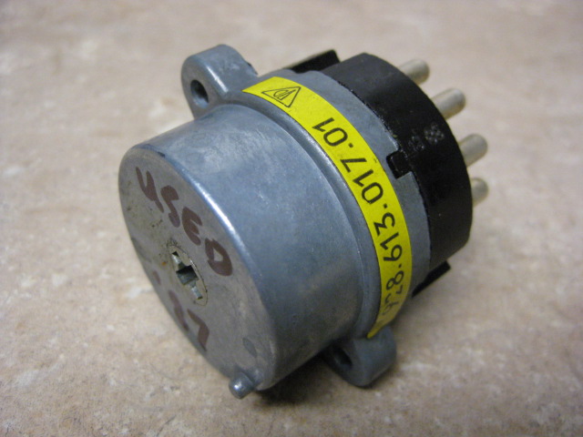
Ignition Switch
The ignition switch is the precursor of the wiring system. Its main function is to open the passages from the battery to the starter and electrical accessories. The switch itself connects to the rear of the lock cylinder which has several wires that connect to to the switch's back. It has five functions, which are listed in the following order:
- Key out - Means everything is off.
- Key in - If a door is open while the key is in, you'll hear a chime, but everything will still remain off.
- Key in - Accessories and radio on.
- Key in - Accessories, radio and ignition on.
- Key in - Accessories and radio off, while ignition is on.
Starter Wiring
Each wire is color coated and gives power to a specific component. One of the switches main functions is to operate the starter and is found on slot 50 of the switch. Current from the switch flows through the yellow starter wire, through the wire harness and into the starter solenoid.

Accessory Wiring
The other wires that connect into the ignition switch are primarily used for the vehicle's accessories system. The two black wires are ignition feeders, gray is the parking light feeder, black/yellow are accessory feeders, and the red/black are used for the radio feeder.

Common Questions
How do you tell if the ignition switch is broken?
There are a few ways to diagnose a malfunctioning ignition switch. The easiest requires using a special tool, called a test light, on the ignition switch to check for power. If the isn't any voltage flowing through the switch, it should be replaced.
In what order do the wires install on the ignition switch?
Each wire on the ignition switch has a corresponding number that is found on the back of the unit. Install each wire according to each number on the ignition switch. Refer to the list below.
- Red wires are in slot 30.
- Black wires are in slot 15.
- The yellow wire is in slot 50.
- The grey wire is in slot P.
- The black/yellow wire are in slot X.
- The red/black wire is in slot R.
Common Issues
No Crank
If the engine does not crank but all the electrical accessories work, then the ignition switch should be promptly tested. Use a test light and check for power through the wire pins.
Ignition Switch Won't Turn
If the switch is stuck, it may just be binding on the steering column. To fix this problem, pour some lubricant into the lock cylinder and attempt to turn the key.
Engine Stalls While Running
This can occur when the contacts inside of a switch are completely worn. Any slight vibration can cause an interruption in the voltage transfer, resulting in momentary loss of power. Repair requires replacing the ignition switch.
Technical Service Bulletins (TSBs)
This data can be found on the NHTSA's website.
- Group 28, NO. 83-03 Steering Locking Cam & Ignition Switch Modified 1983-10-04
Related Discussions
- Ignition Switch Wiring Question - Rennlist.com
- Ignition Switch Wiring, What Color Goes to What? - Rennlist.com