When you click on links to various merchants on this site and make a purchase, this can result in this site earning a commission. Affiliate programs and affiliations include, but are not limited to, the eBay Partner Network.
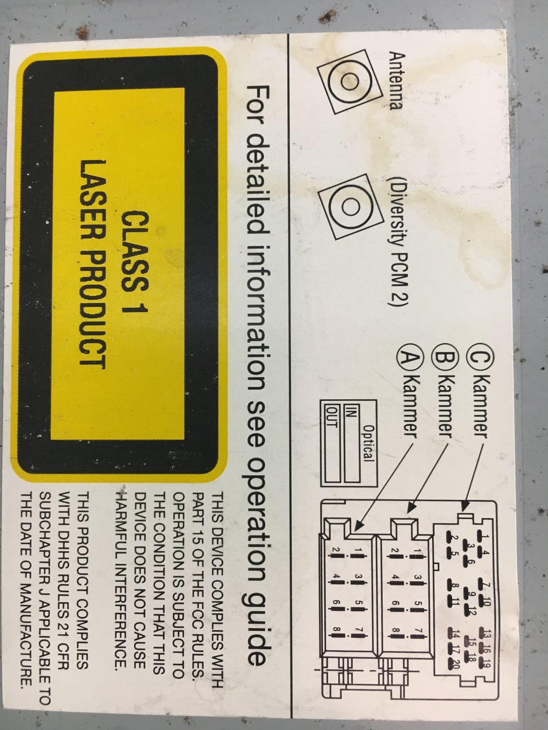
Not having a wiring diagram to go by is always just WAG about what goes where, but going by a 2001 wiriing diagram none of the wires have the same color as any of the CAN H/L lines that are at other places in the diagram.
Furthermore, looking at the diagram I see no CAN lines at the PCM.
Alright, maybe someone knows the answer to this question then...
My PCM has a digital clock display. My instrument panel also has a digital clock display. They seem to be in sync so they must be electronically linked. Doesn't that mean there has to be wires running between the two and if so, are they not the CAN high and low?? (Which means at least two of the wires in the pic have to be them?)
Change one clock and see if the other changes too.
If the other changes concurrently with the other one then I'd say they are indeed linked.
And by CAN could certainly be possible. But without a wiring diagram it is hard to know which lines are CAN. If the car is on and the CAN bus active the lines would be electrically active but I have never bothered to use a volt/ohm meter to "look" at the CAN lines/signals.
CAN is a differential bus and I believe the voltage levels on both lines would read around +5V but like I said I've never used a volt/ohm meter to look at CAN signals. I used an analog or digital logic scope so I could see the line signal pulses and I was using a relative inexpensive CAN bus simulator not a real car's CAN bus. The only thing I plugged into the car's CAN bus was a CAN bus snooper, Vehicle Spy.
You have to be very very careful. Static discharge into a CAN line and you could blow some expensive processors.
Talos Takes Your 991 Porsche 911 GT3 to the Next Level for a Cool $1.13 Million
Slideshow: Talos Vehicles has transformed the Porsche 911 GT3 RS into a carbon-bodied, race-inspired machine that costs well over $1 million before the donor car is even included.
9 Vehicles Porsche Helped Engineer that Aren't Porsches
Slideshow: Long before engineering consulting became trendy, Porsche was quietly helping other automakers build everything from supercars to economy hatchbacks.
9 Features and Characteristics That Only Porsche People Understand
Slideshow: Some brands build cars. Porsche builds traditions, obsessions, and a few habits that stopped making sense decades ago but somehow became part of the charm.
This Builder Is Turning Heads With Its Slantnose 911 Creation
Slideshow: A small Polish tuner has reimagined the Porsche 911 Slantnose for the modern era, blending 1980s nostalgia with widebody tuning culture and serious performance upgrades.
Porsche 911 GT3 Artisan Edition Pays Homage to Japanese Culture
Slideshow: Porsche has created a Japan-only 911 GT3 Artisan Edition that blends track-ready hardware with design cues inspired by traditional Japanese craftsmanship.
Porsche Reveals Coupe Variant of the Electric Cayenne With a Fresh Look
Slideshow: Porsche's latest electric Cayenne Coupe blends dramatic styling with supercar acceleration, turning the brand's midsize SUV into a 1,139-horsepower flagship.