When you click on links to various merchants on this site and make a purchase, this can result in this site earning a commission. Affiliate programs and affiliations include, but are not limited to, the eBay Partner Network.
any reason not to tack-weld the ring to the FW in a few spots?
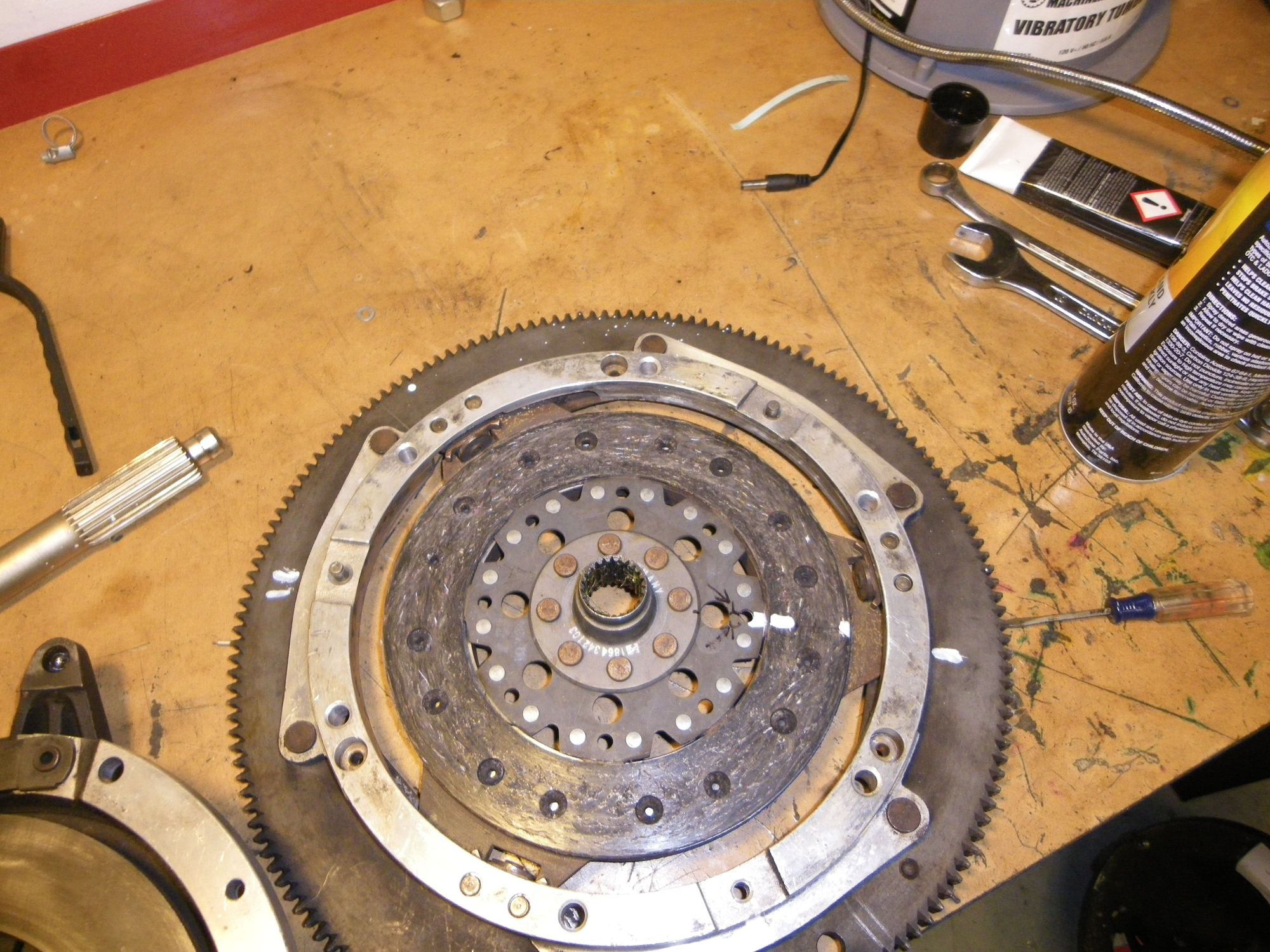
We have had mixed results with that. When we have tried we often get stress cracks just outside the weld once the weld cools. Dissimilar metals and dissimilar heat shrinkage rates. Anyway - pinning it was a better solution.
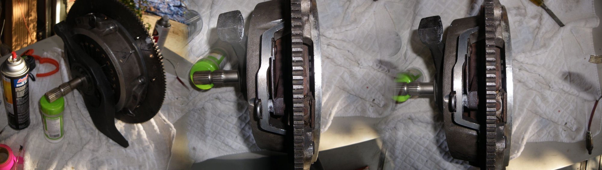
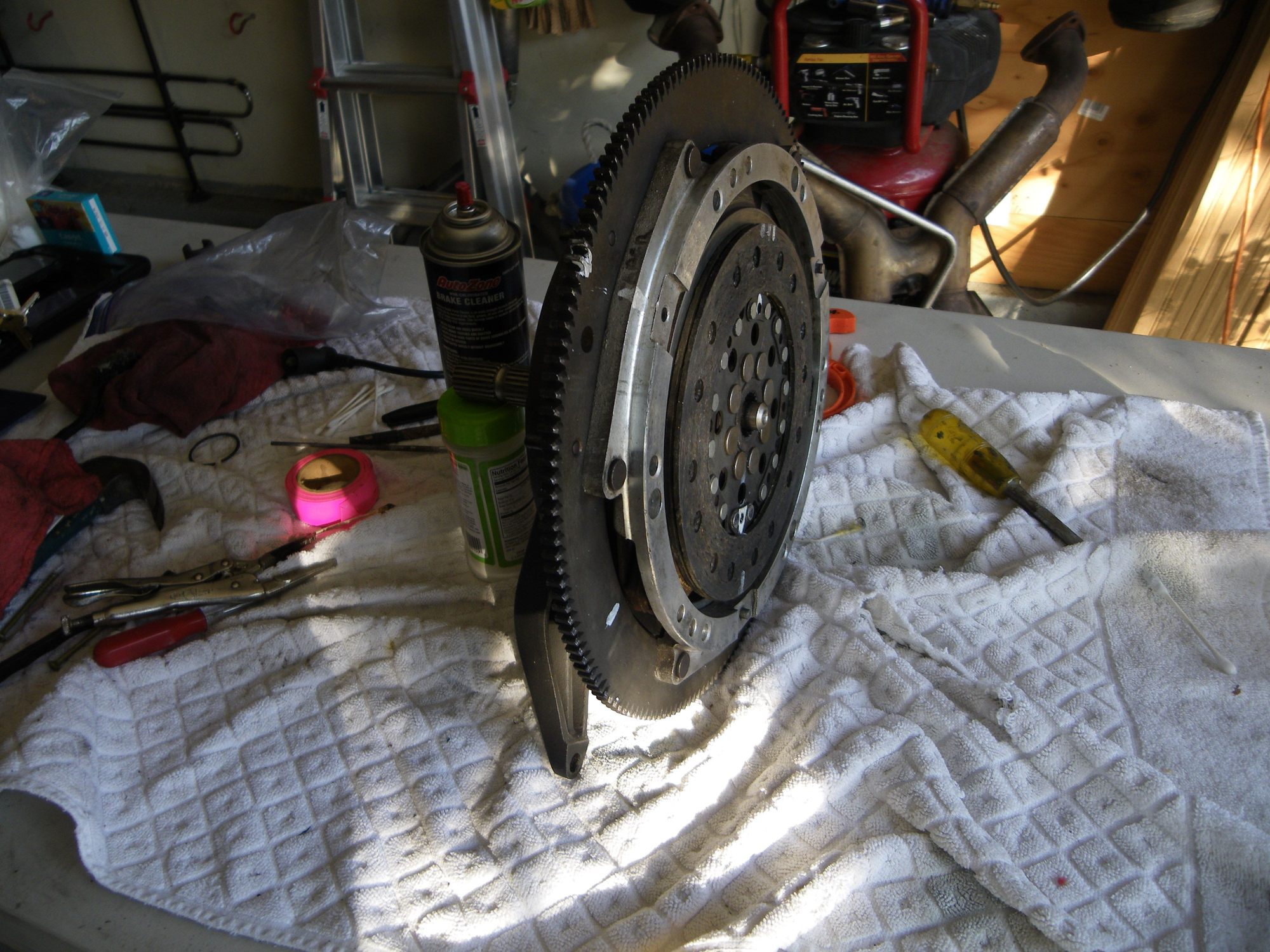
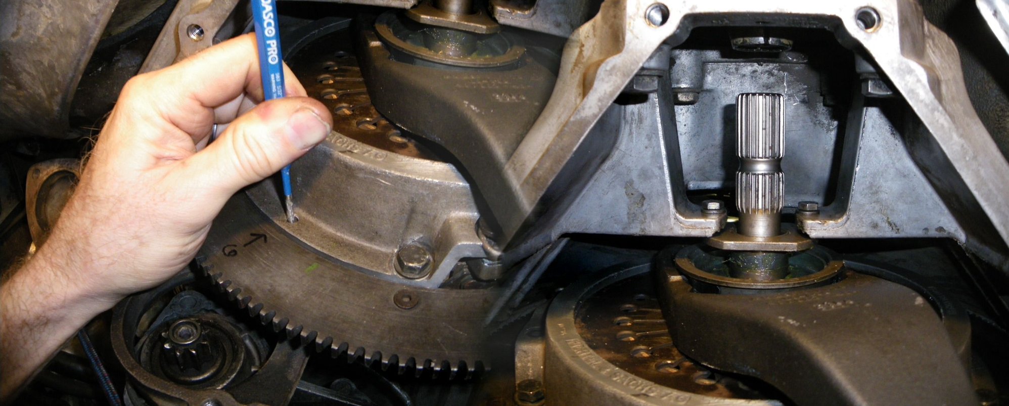
Greg at Precision re positioned my ring gear and pined it instead of welding. Photos below.
I have the repaired flywheel back in the car along with the clutch. I will post some dual disk clutch R and R photos / steps for others to refer to on a S3. I also replaced ball cup.
I adjusted the dual disk intermediate plate and will do a write up on what I did with it (provided it operates correctly!). Perhaps useful in light of my disk being towards end of service lie Also did my own rebuild on the throw out bearing that Ill post the steps on
Also installed Greg Brown clutch hose - brilliant!
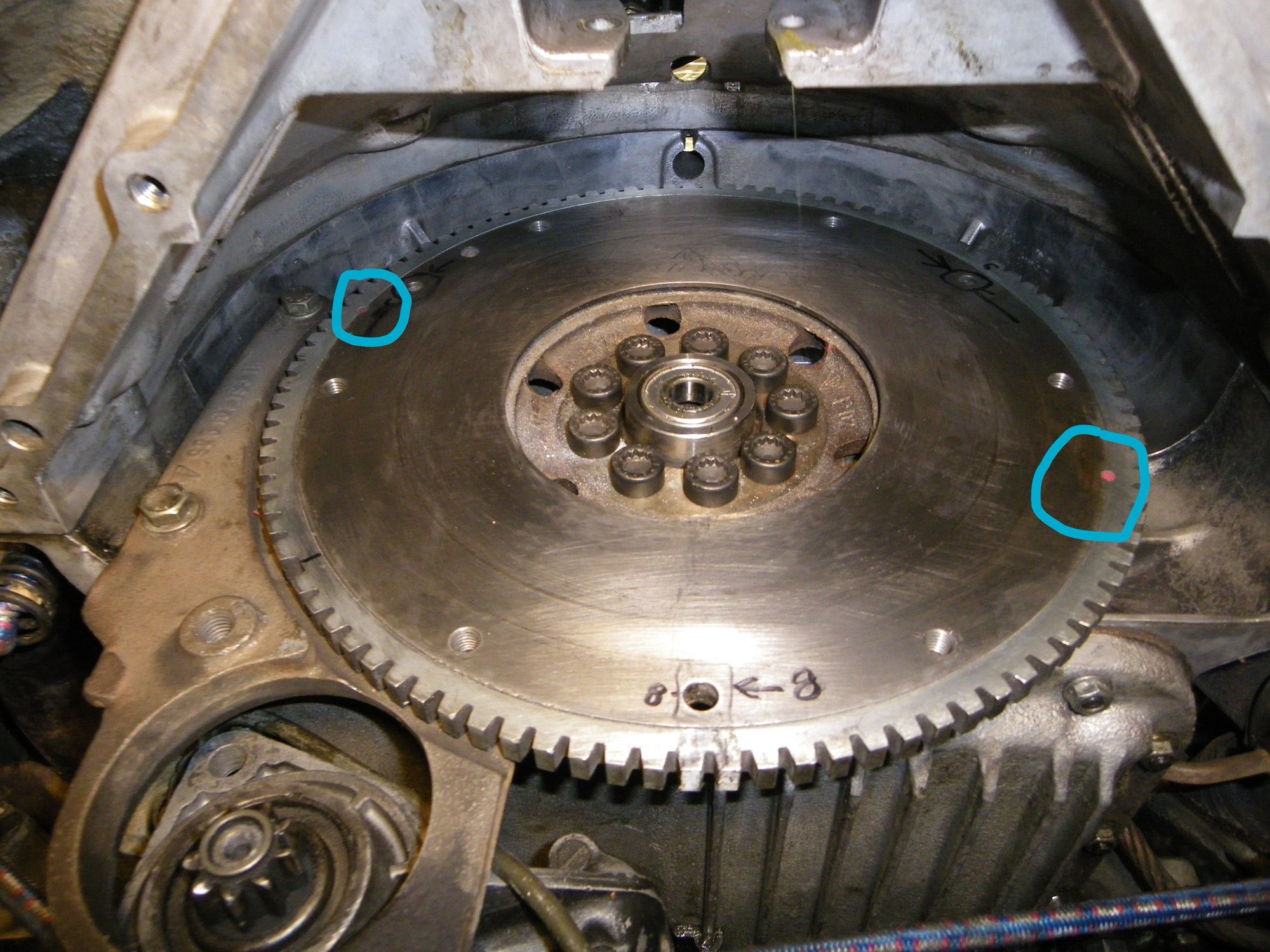
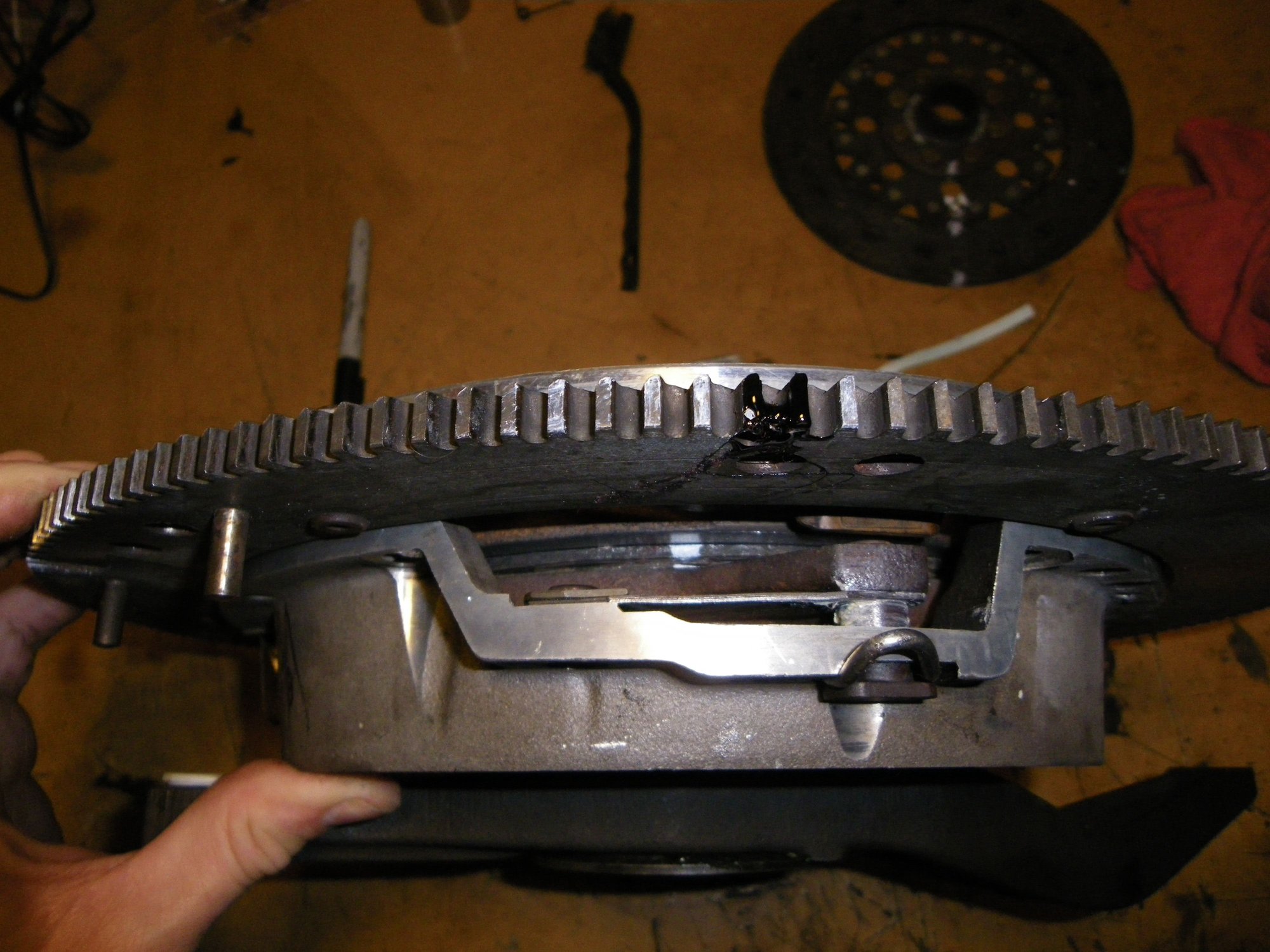
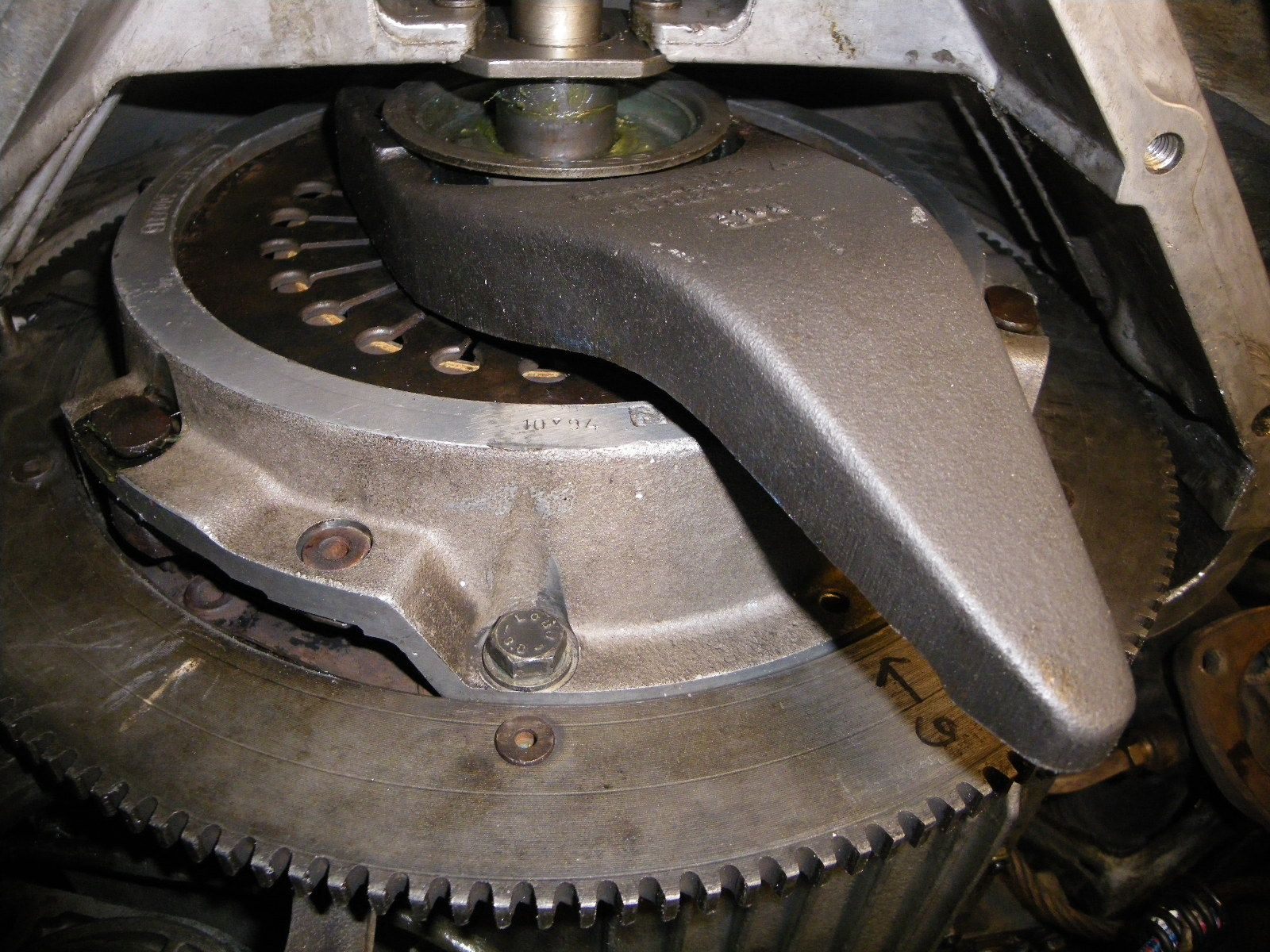
See Blue circles - where Greg pinned the flywheel. Said he had never seen a ring gear as loos as the one on my car
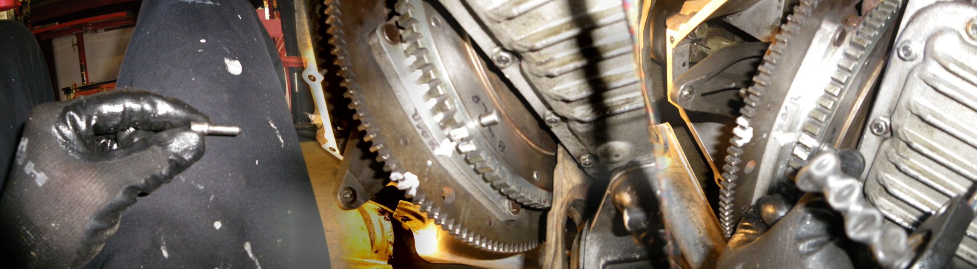
Remember to use a good quality 12 mm triple square socket!
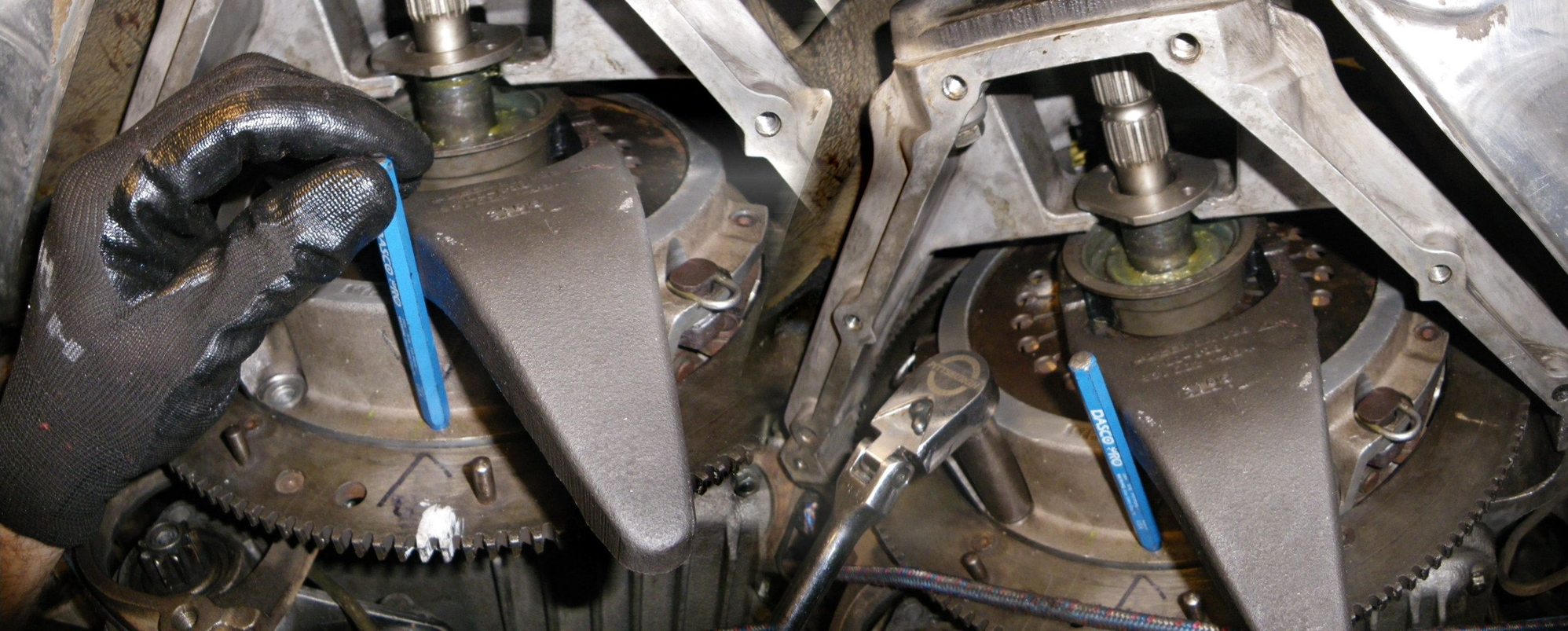
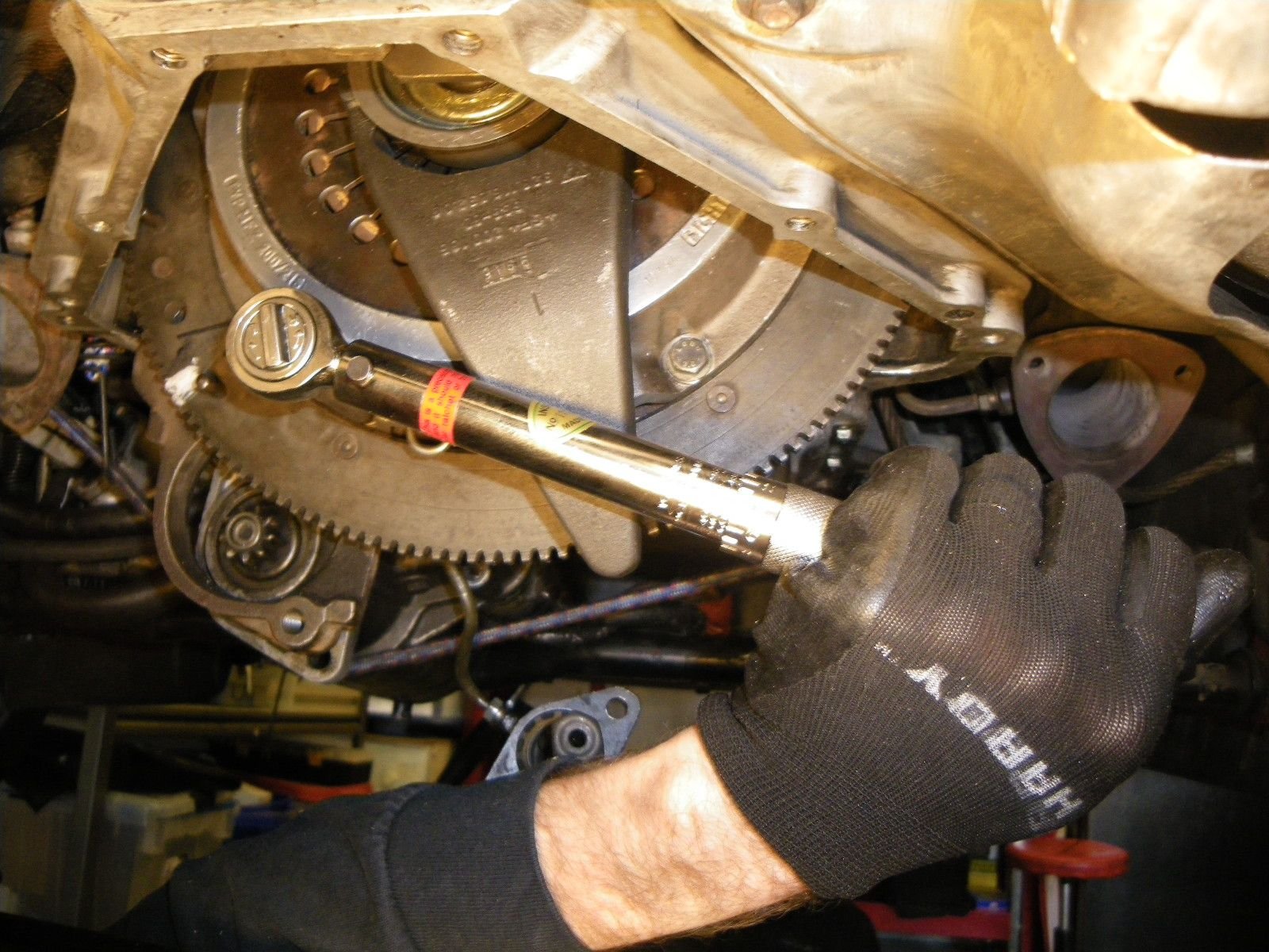
Removing the pilot bearing after flywheel was reinstalled. Wrench in photo was used to hold flywheel in place when torquing bolts to 65 ft lbs
[ATTACH]1112067
Glad you were able to get it sorted Pete, sorry I wasn't more help at Sharktoberfest (mine was the car we couldn't get a timing light reading on) but great job ruling everything else out and getting to an initially unlikely root cause.
At Long last (yesterday), I got my clutch, exhaust system, Greg Brown clutch hose etc. assembled and attempted to start the car for first time in 6 months.
Success, it started in less than 2 seconds and ran almost perfectly. FINALLY, FINALLY FINALLY I have the major problem with this car sorted and fixed. It was a slipped timing ring gear on the flywheel as outlined above
Because I pulled the clutch to replace the flywheel, I replace the pilot bearing, throughout bearing and adjusted the intermediate plate
Here are some photos of the throughout bearing rebuilt. I was able to press out the old bearing using some PCV pipe, a vise, a 1” socket. Will also post photos of how I adjusted the intermediate plate. The clutch is operating perfectly
Tools used to press out old bearing
Inserting 1" socket to press out the cover
Pressing out the throw out bearing cover using the 1" socket, long bolt and nut and big washer
Here is the throw out bearing cover popped loose
Pulling bearing cover
Using a PVC pipe as a tool to press the bearing out of the throw out bearing body
Using the vise and PVC pipe to press out the bearing from the body
Car is now pulling 18 to 19 inches of vacuum vs the 11 to 12 it was puling before and running well. Timing at idle checked with a timing light is now 10 degrees BTD vs 15 degrees ATDC with the slipped ring.
Next Steps
1. R and R all hoses due to contamination form leaking radiator oil cooler
2. R and R timing belt + new accessory belts
3. Install new tie rod ends and bellows due to split boots
4. Drain refill transaxel with redline
5. Clean injectors
6. Rear Half-shaft - repack (no slipts in boots, but original to the car)
Already Done
1. Timing ring
2. Clutch TOB and adjustment and ball cup and Gregg Brown hose
3. Fuel filter
4. TPS switch replaced
5. Top end refresh
Here are steps I used to install the dual plate clutch in my 86
I moved flywheel so that the 8 mm dowel pin was facing bottom
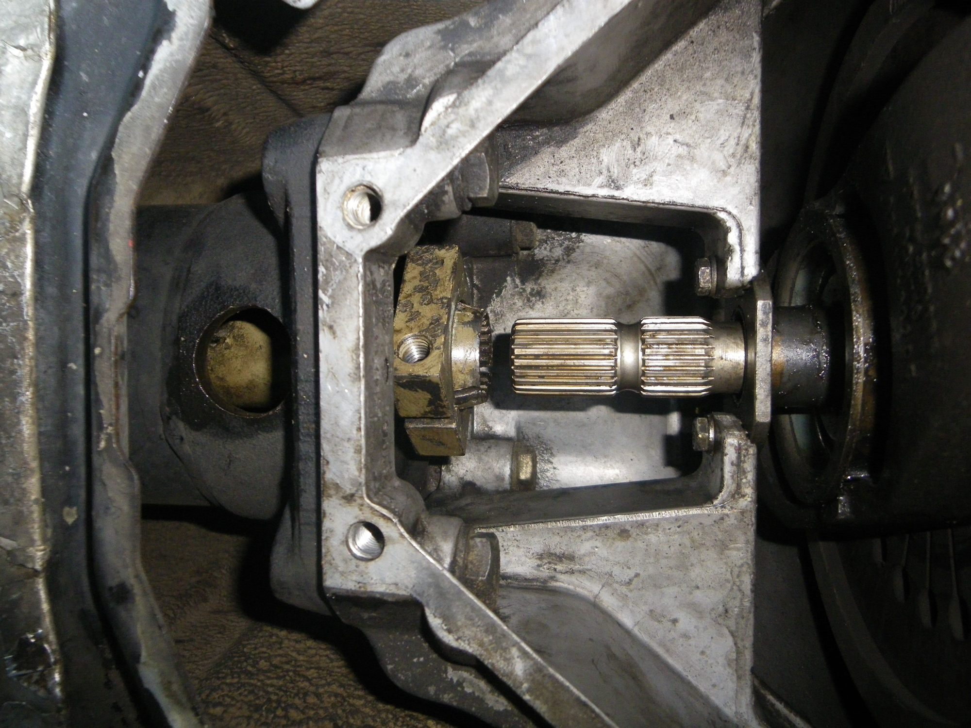
Push the torque tube coupler back as far as possible - approximately flush with the bellhousing. This photos is from the removal but coupler is gold part to left side of intermediate shaft
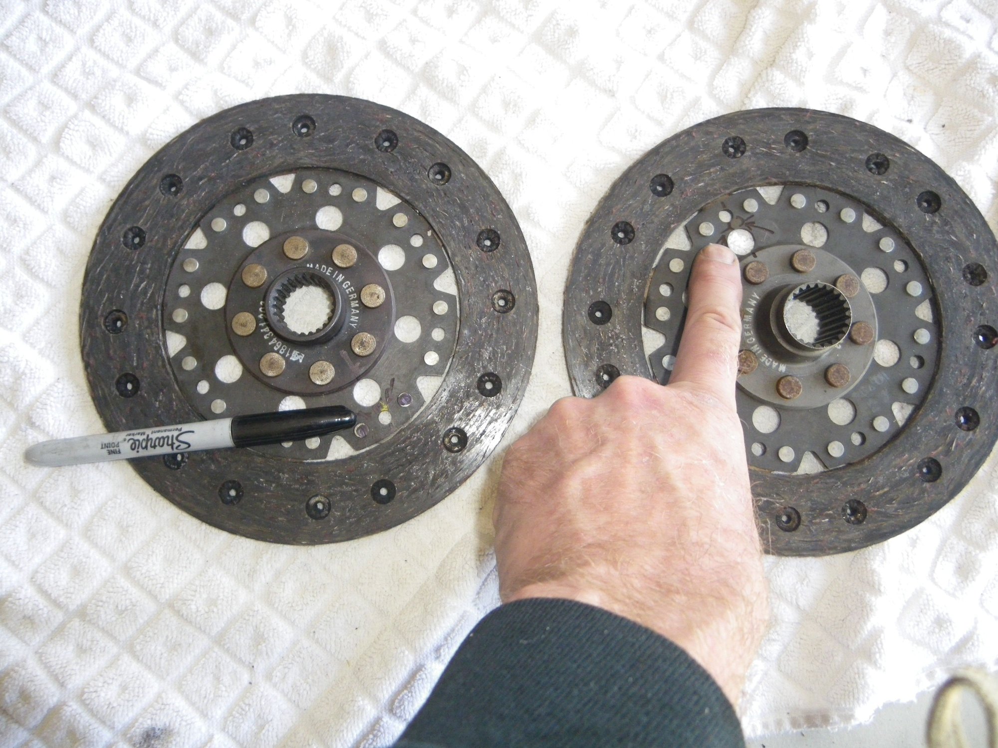
Find balance marks (typically yellow dot) on the clutch disks so they can be aligned opposite of each other. I reused old disks and difficult to see the marks
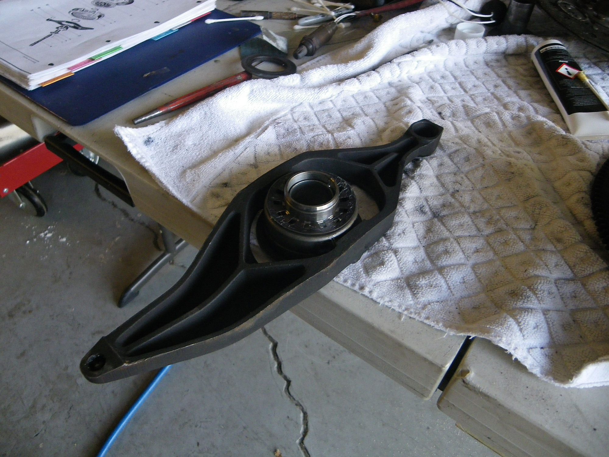
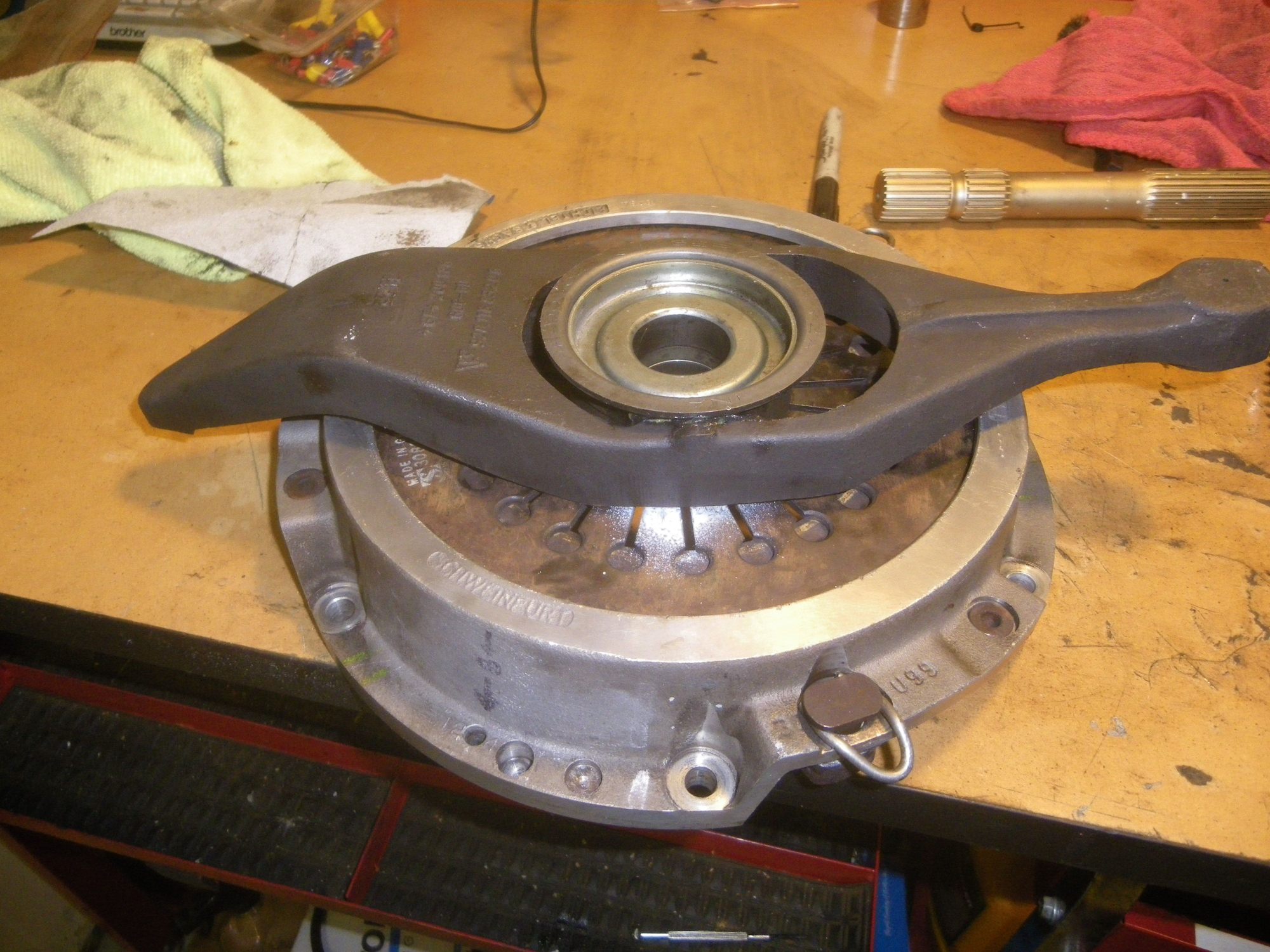
Insert Throw Out bearing into arm. NOTE DO NOT INSTALL BALL CUP INTO ARM, INSTALL NEW BALL CUP ON BELL HOUSING BALL, SEE PHOTO
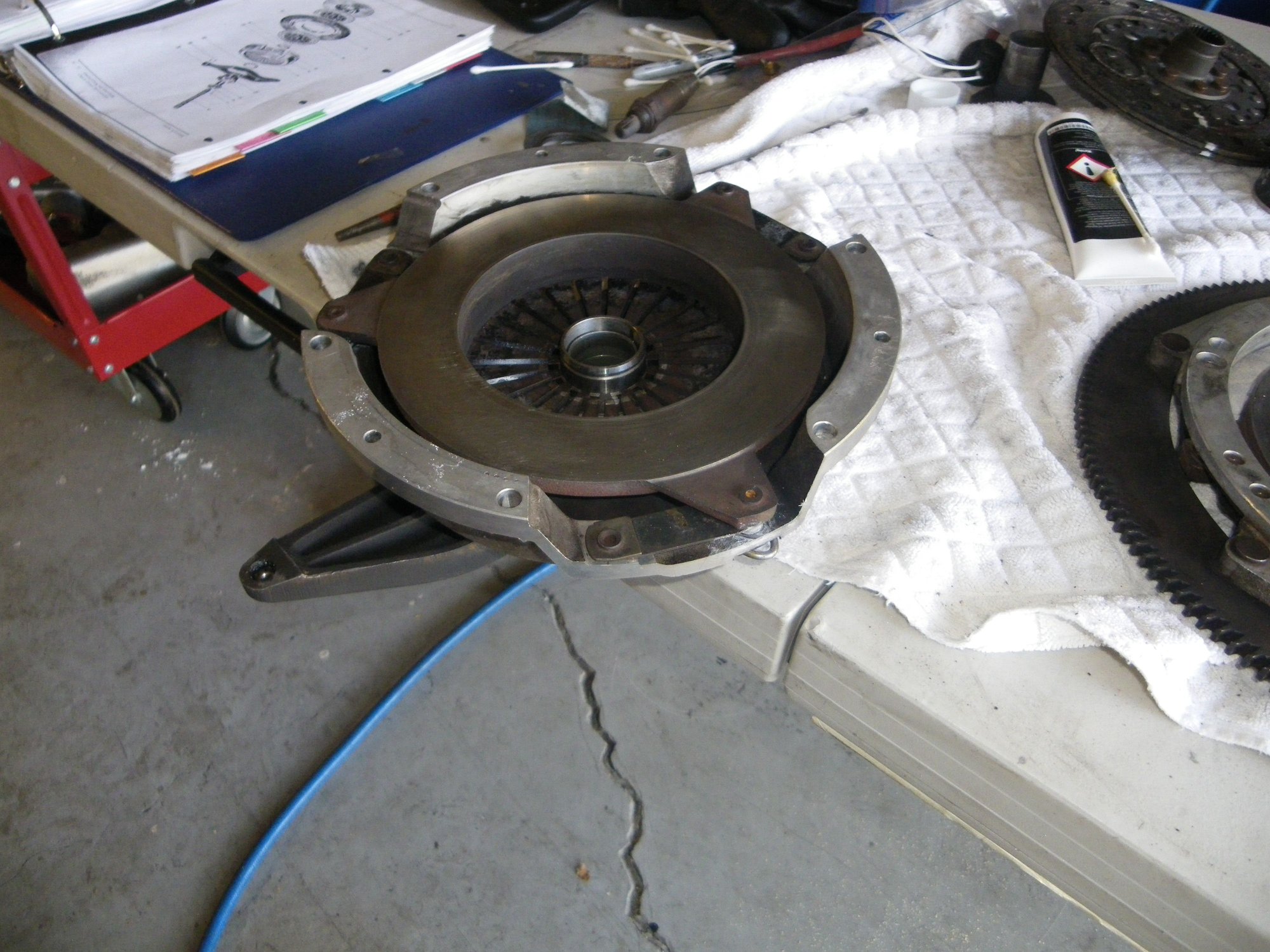
Place pressure plate over arm and throw out bearing. Assemble throw out bearing and washer per diagram in WSM, Note, my pressure plate had the 3 mm spacers inserted at removal - I believe a new pressure plate will come with them already furnished to ease installation
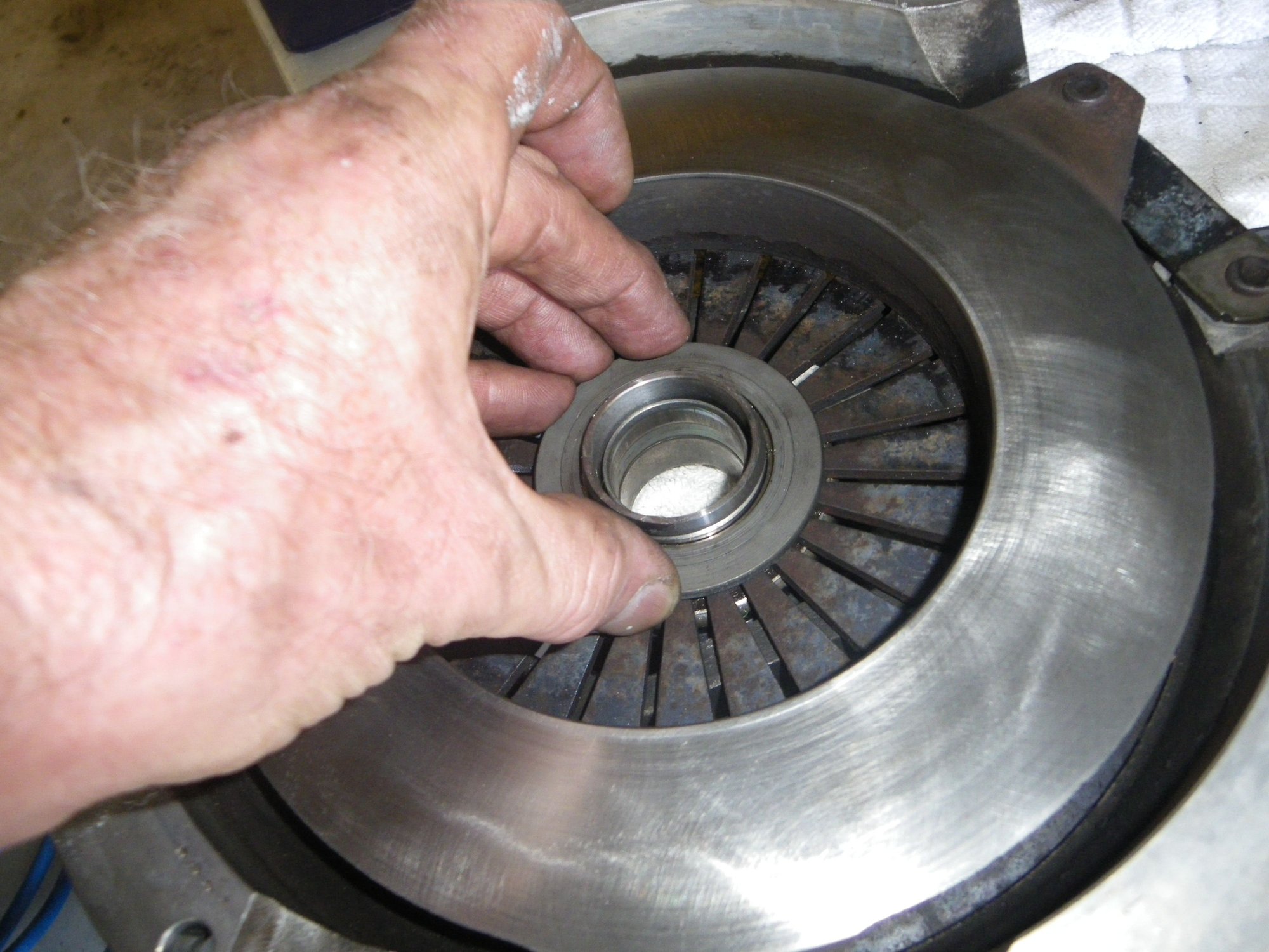
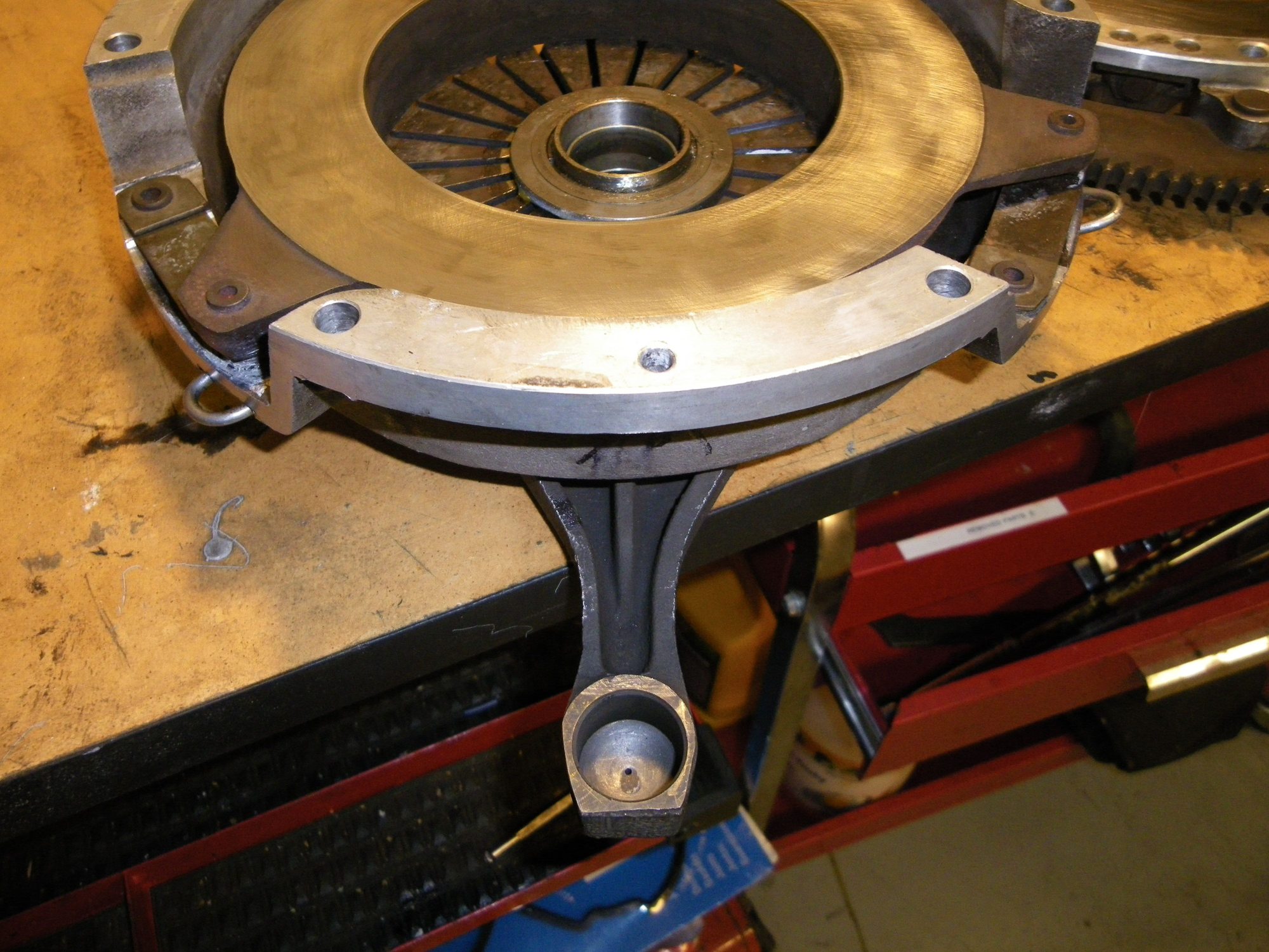
Installing large washer? on inside face of pressure plate prior to installation of clip that hold the throw out bearing to the pressure plate fingers
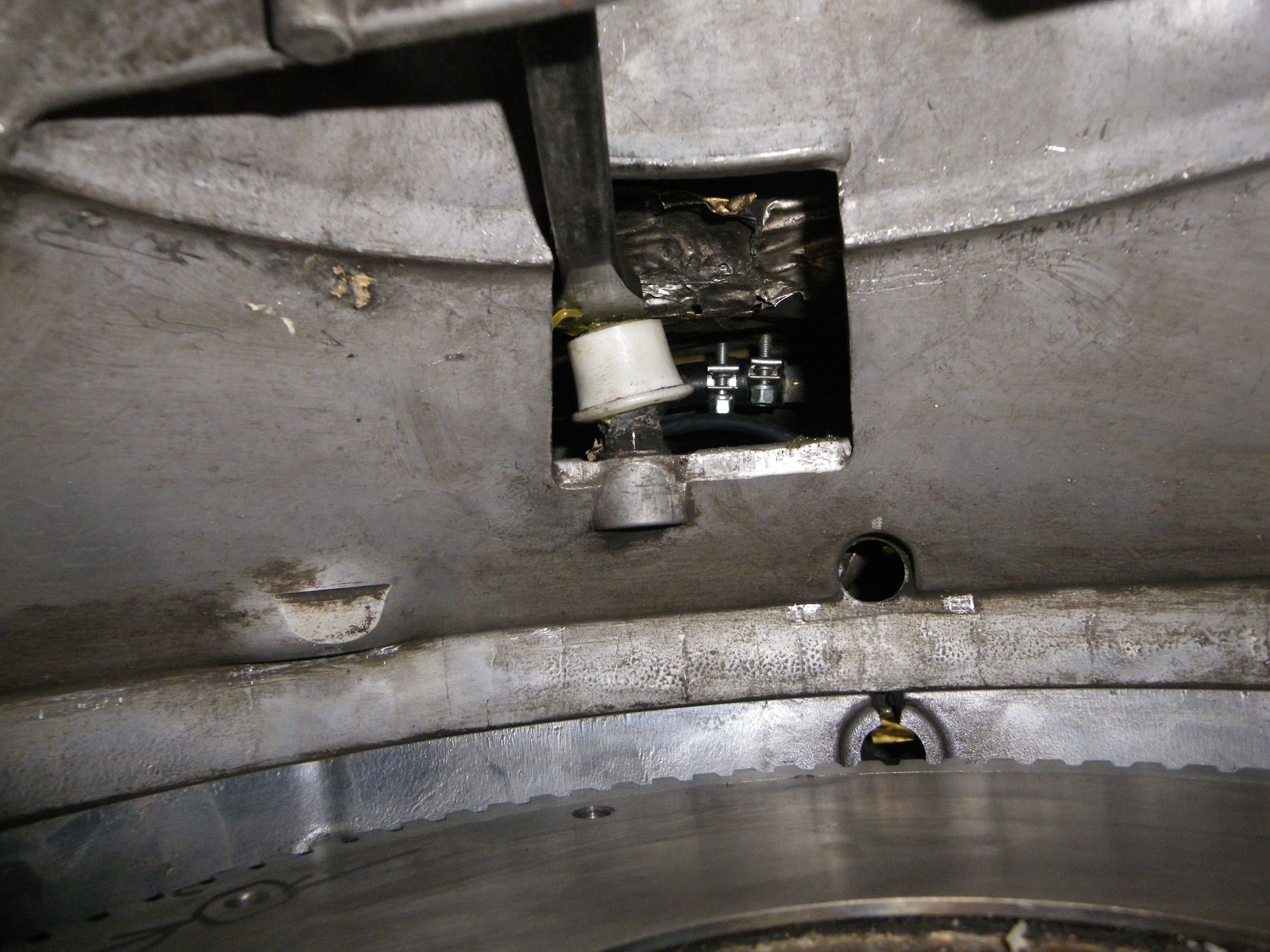
Ball cup on bellhousing ball. DO NOT INSTALL ON THE ARM. Be sure to grease ball cup per WSM
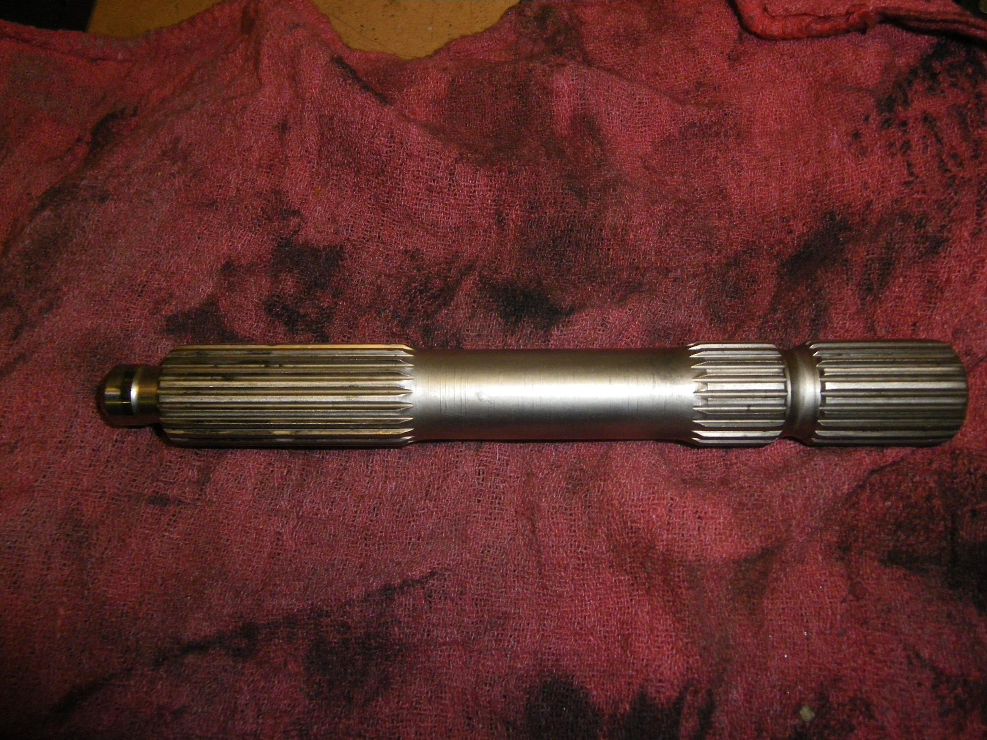
Grease splines of intermediate shaft (left side). Make sure to get the correct grease. Got mine form Rodger at 928Rs
Assembled pressure plate, arm and rebuilt throw out bearing
Other side of arm, pressure plate
Placed outer disk on intermediate plate as shown and added white paint marks to assure I could see that the yellow marks on the disks were aligned 180 degrees opposite of one another when viewed sideways under the car as I was holding the pack together to install it on the flywheel
Marked the flywheel as well so could assure disks were aligned with imbalance 180 degrees opposite
Place inboard disk (disk at flywheel side) (hold in place, rotate to correct orientation relative to outboard disk and insert intermediate shaft
Here are continued steps I used to install my clutch
I did not get a lot of photos as the pack is heavy and I was working alone. Couple of hints
1. Install ball cup on the bell housing ball, not in the arm!
2. Press torque tube coupler back as far as you can
3. Use clean gloves and be sure not to contaminate intermediate plate, flywheel or disks with grease
4. Use a sharpie to make marks on the flywheel and pressure plate to get the two 6 mm and one 8 mm dowel pin oriented to corresponding holes in fly wheel
Orientation of flywheel
Clutch Pack (heavy)
While under the car, carefully lift clutch pack into bell housing while maintaining the alignment of the disks. Get pack aligned with the dowel pins. Not clear in this photo, but I marked on the pressure plate where the different pins by size were located with sharpie. The intermediate shaft and its length sticking out of the pack where it goes into the pilot bearing was for me a trial and error then success exercise. I also use a punch in the 8 mm hole to help hold the pack in place
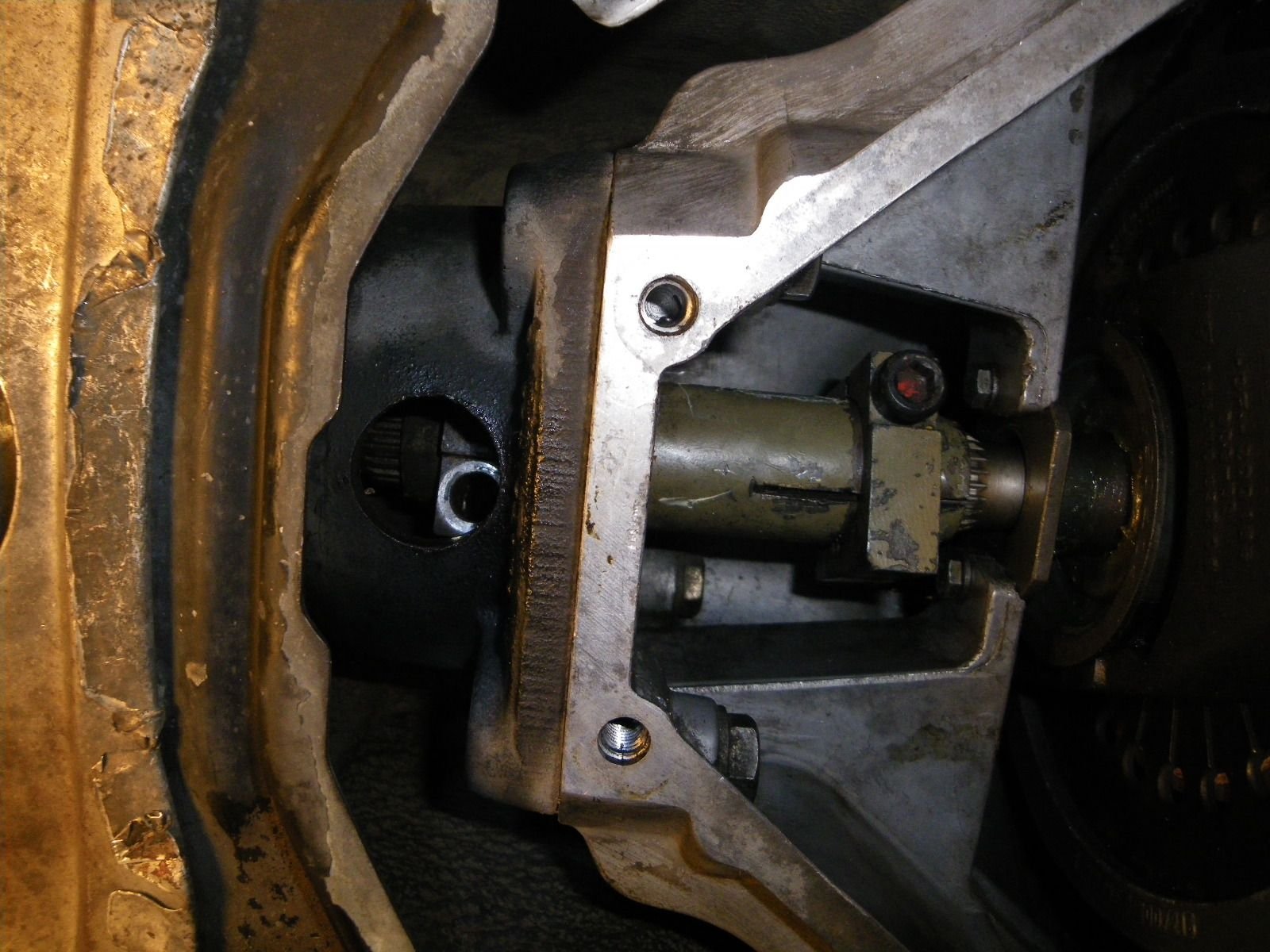
I learned the hard way that the guide tube needs to have its ears inboard (towards engine). The photo below shows the guide tube correctly positioned. Was hard to take photos while manhandling the circa 30# clutch pack
Incorrect location of guide tube. ****ttttttttttttttt
Guide tube in correct location. Flywheel bots installed. Driving 6 mm dowel pins towards flywheel.
After getting pack inot correct locaton, installing 6 flywheel to pressure plate bolts, I inserterd the top of the arm onto the ball cup at the top of bell housing. Torqued flywheel bolts to flywheel
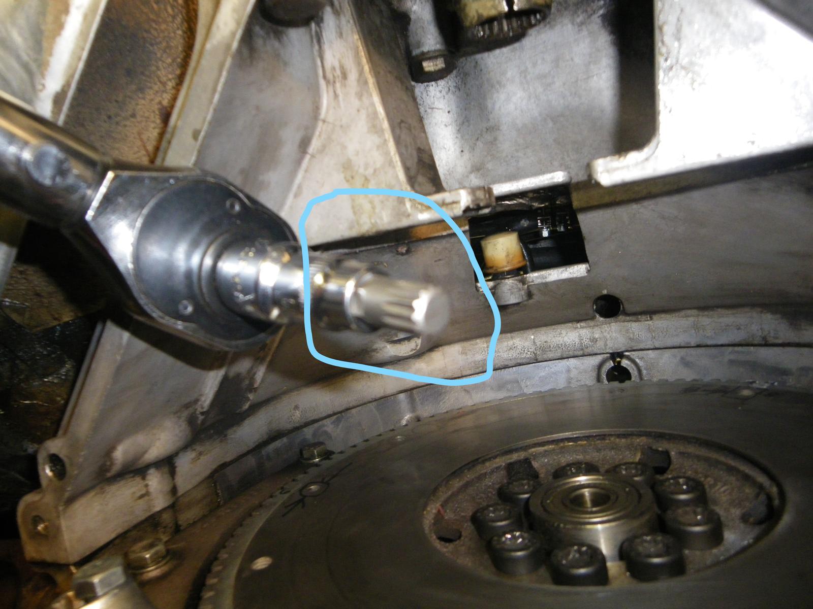
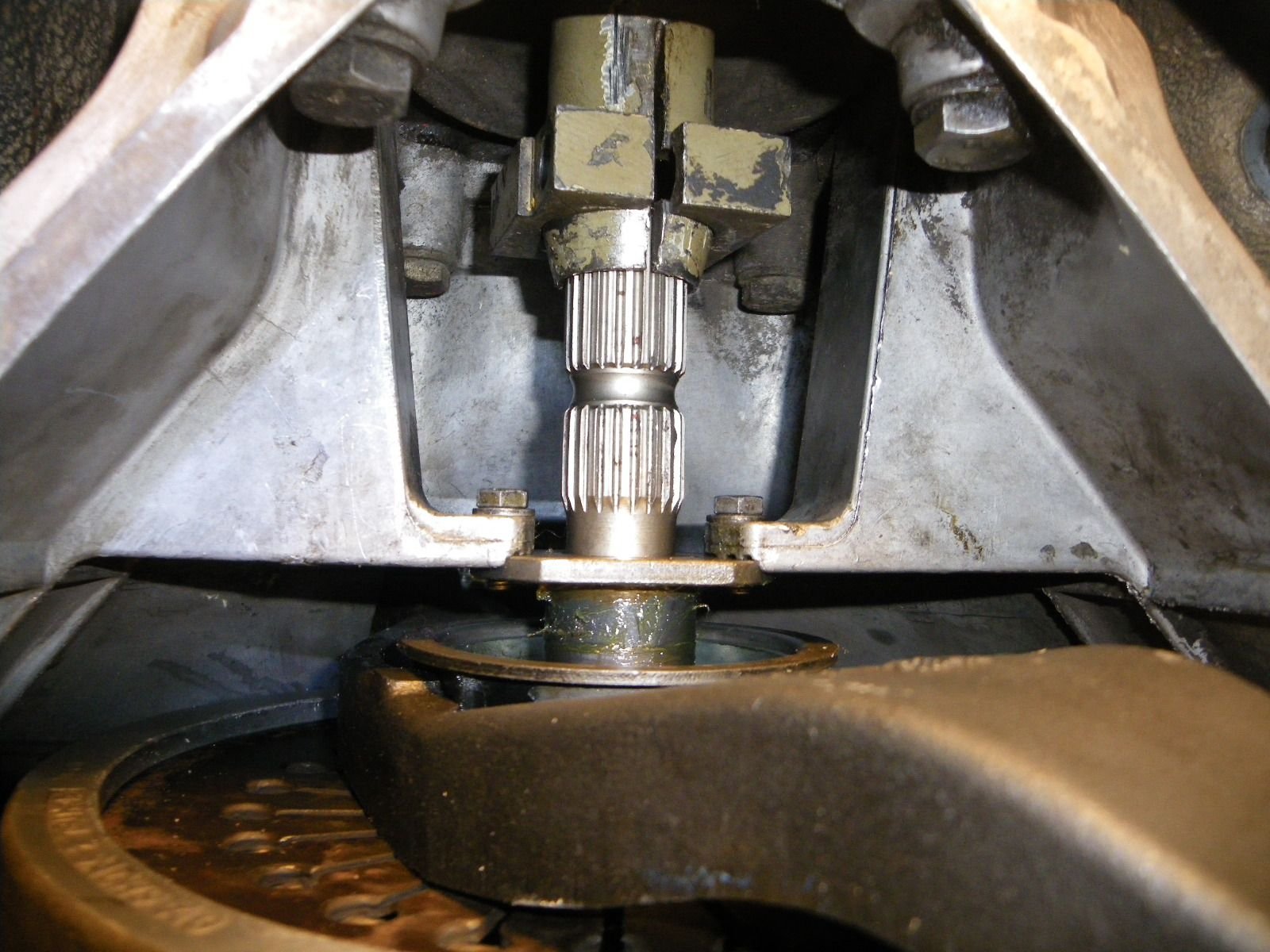
Make sure intermediate shaft is fully inserted into pilot bearing in flywheel. Moved coupler onto intermediate shaft
Coupler on the intermediate shaft
Inserting 8 mm stepped pin from engine side of flywheel


 11-14-2016, 12:05 PM