When you click on links to various merchants on this site and make a purchase, this can result in this site earning a commission. Affiliate programs and affiliations include, but are not limited to, the eBay Partner Network.
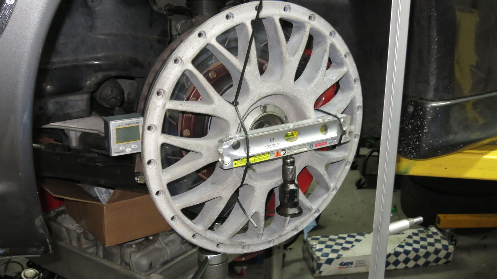
I am trying to measure Bump Steer on a GT3 My setup looks like this:
I am just using from full droop to the compression of the helper spring - so not the 'correct' wheel travel.
My problem is that as I lift the control arm, I am seeing a rotation in the wheel - a total of 1 degree (measured with the level gauge seen on the left side of the wheel. The wheel and or rotor is not being touched in any way.
What and why is this happening? Is this some caster effect?
I am changing ride height ( Tripod under LCA) and measuring change in multiple axis.
As I increase ride height from full droop, I plot the toe change on the far wall, I note the rotation of the brake rotor, and I measure the distance the center of the wheel moves from the centerline - essentially plotting the camber.
The toe change is the positional change of the laser dot
The rotation of the brake rotor is measured by the digital angle finder
I measure the distance the wheel center moves from the center line using the Al C channel I set up - used a level to get it vertical
What I see that I don't understand, is that as I change the vertical position of the wheel, there is a rotation of the brake rotor - a 3" change gives me 1.2 deg of rotation.
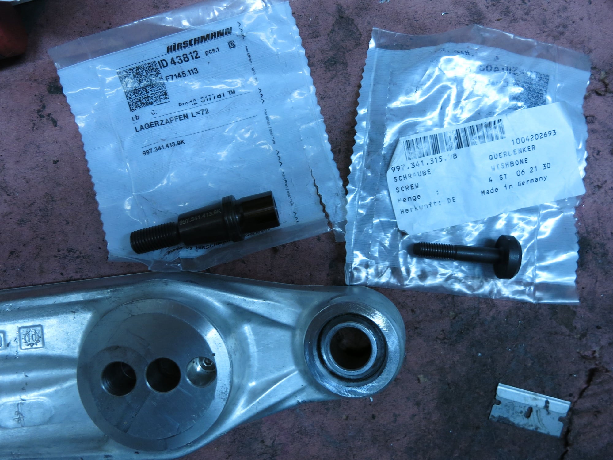
Details of the front suspension:
996 GT3RS Upright
996 RSR front cross member
997 RSR Compression rod - set at minimal dive
997 RSR LCA + monoball
RSR Tie rod
When you say rotation I think you mean rotation about the wheel axis (same rotation as if the axle was rotating). Assuming this is what you are asking about - the lower ball joint os goimg to move fore and aft with suspension travel and the top of the upright will also move but a different amount because of the suspension geometry (unequal length arms at various angles). The relative fore/aft motion of top and bottom of the upright will appear as a rotation of the brake rotor about the drive axis.
Typically you use two dial indicators. One at the front of the wheel and one at the back of the wheel you run the suspension through its travel and measure the relative displacement of the dial indicators. I don't quite understand how you are measuring bump steer based on your photo but what I described is the way it is usually done.
Another way it can be done is by attaching a mirror to the face of the wheel and shining a laser at it. Put a board opposite the wheel to see the relected laser spot. Place a vertical line on the board for reference. then move the suspension through its travel and you'll see the reflection of the laser moving forward and backwards with bump steer as the angle of the mirror changes. The reflected laser will purely vertically if no bump steer.
this is the method:
http://www.advancedracing.com/bump_steer_gauge.php
Thanks, I am familiar with both of these. The original way I did it was to use a spare centerlock bolt, drill and tap a hole in the center, and attach a laser level - you can see it hanging down in the picture, and focusing on a target on the wall. I was double checking my results by attaching the level to a wheel face from my wall of shame (cracked magnesium). This is essentially the same as your second link, but because I have centerlocks I can precisely attach the laser to the center of the wheel. That is how I saw this effect.
Thanks, I am familiar with both of these. The original way I did it was to use a spare centerlock bolt, drill and tap a hole in the center, and attach a laser level - you can see it hanging down in the picture, and focusing on a target on the wall. I was double checking my results by attaching the level to a wheel face from my wall of shame (cracked magnesium). This is essentially the same as your second link, but because I have centerlocks I can precisely attach the laser to the center of the wheel. That is how I saw this effect.
Ray
Attaching the laser to the hub will not give you accurate information because of exactly the phenomena your original question was regarding. The hub does not move in a purely vertical plane - it translates fore and aft and rotates in all directions. This rigid body movement due to the suspension kinematics (relative lengths of the links and mounting positions) will move your laser spot around foreward/backward/left/right. The point of putting the mirror on the hub and reflecting the laser off it, is that ONLY the angular changes in the hub (+- camber and +- toe) will move your reflected spot on the target. Up and down movements of the spot are due to camber changes (laser will move up with increasing negative camber as the mirror rotates). Left and right movements are due to toe changes (when facing the reflection, the spot will move right for toe in, left for toe out). If Camber and toe remain constant (and your mirror is perfectly flat) the reflected spot remain completely stationary as the suspension moves through travel. This is not the case if you mount the laser to the hub directly.
Hope this makes sense - but mounting the laser to the hub is basically useless for measuring bumpsteer.
I posted here initially after a few beers and realized I misunderstood the post I was intending to reply to. Haha. I think it would be great to understand the bumpsteer and how to measure on jacks as I think I am encountering bumpsteer induced rear tire wear on my car to a certain extent.
Last edited by haulinkraut; 05-07-2018 at 01:03 PM.
I am changing ride height ( Tripod under LCA) and measuring change in multiple axis.
As I increase ride height from full droop, I plot the toe change on the far wall, I note the rotation of the brake rotor, and I measure the distance the center of the wheel moves from the centerline - essentially plotting the camber.
The toe change is the positional change of the laser dot
The rotation of the brake rotor is measured by the digital angle finder
I measure the distance the wheel center moves from the center line using the Al C channel I set up - used a level to get it vertical
What I see that I don't understand, is that as I change the vertical position of the wheel, there is a rotation of the brake rotor - a 3" change gives me 1.2 deg of rotation.
Details of the front suspension:
996 GT3RS Upright
996 RSR front cross member
997 RSR Compression rod - set at minimal dive
997 RSR LCA + monoball
RSR Tie rod
Ray
What ride height are you running? I know the RSR stuff is designed for pretty sub cup ride height hence the bump adjustability. Are you also on RSR subframes?
Front ride height has been between 95 - 100mm. Yes on the subframes - front and rear. Rear has been ~ 125 mm - I am unable to run lower due to the wheel wells. Been wondering about rake as well. Been running 25-30mm rake. The cup cars ONLY work as well as they do because of the astronomical spring rates which essentially remove all compliance (my opinion). I was hoping that I could run softer rates AND lower the car while not giving up on compliance. It does open a boatload / pantload /... of tuning issues, for example - what is the correct rake / ride height. What about rear CASTOR (not camber) since we can also adjust it.
Attaching the laser to the hub will not give you accurate information because of exactly the phenomena your original question was regarding. The hub does not move in a purely vertical plane - it translates fore and aft and rotates in all directions. This rigid body movement due to the suspension kinematics (relative lengths of the links and mounting positions) will move your laser spot around foreward/backward/left/right. The point of putting the mirror on the hub and reflecting the laser off it, is that ONLY the angular changes in the hub (+- camber and +- toe) will move your reflected spot on the target. Up and down movements of the spot are due to camber changes (laser will move up with increasing negative camber as the mirror rotates). Left and right movements are due to toe changes (when facing the reflection, the spot will move right for toe in, left for toe out). If Camber and toe remain constant (and your mirror is perfectly flat) the reflected spot remain completely stationary as the suspension moves through travel. This is not the case if you mount the laser to the hub directly.
Been thinking about this as well, and I need to verify this with some experimentation, BUT I guess I don't see this. I am thinking that there is NO effective difference between mounting a laser on the rim / up-right as a mirror since the mirror will also reflect all changes in x,y,z, and rotation. By compensating for rotation (easy to do if I am measuring it) I can essentially eliminate it - at least that is the theory.
I also think I understand the rotation I am seeing - since the strut is not orthogonal (in part castor) to the road surface, AND most joints have movement, when the ball joint raises, there is a vector that essentially rotates the leading edge of the rotor
Front ride height has been between 95 - 100mm. Yes on the subframes - front and rear. Rear has been ~ 125 mm - I am unable to run lower due to the wheel wells. Been wondering about rake as well. Been running 25-30mm rake. The cup cars ONLY work as well as they do because of the astronomical spring rates which essentially remove all compliance (my opinion). I was hoping that I could run softer rates AND lower the car while not giving up on compliance. It does open a boatload / pantload /... of tuning issues, for example - what is the correct rake / ride height. What about rear CASTOR (not camber) since we can also adjust it.Been thinking about this as well, and I need to verify this with some experimentation, BUT I guess I don't see this. I am thinking that there is NO effective difference between mounting a laser on the rim / up-right as a mirror since the mirror will also reflect all changes in x,y,z, and rotation. By compensating for rotation (easy to do if I am measuring it) I can essentially eliminate it - at least that is the theory.
I also think I understand the rotation I am seeing - since the strut is not orthogonal (in part castor) to the road surface, AND most joints have movement, when the ball joint raises, there is a vector that essentially rotates the leading edge of the rotor
Ray
What spring rates are you running? Are you full interior? Another thing to keep in mind is the cups run pretty tall rear tires which makeup some of the negative attributes of high spring rates. And with spring rates and other alignment setting I would gather the cars are being pushed farther and as a result are more compliant. I can't imagine the cup alignment settings on those cars reflecting a lack of compliance. Just my theory.
I am running 1100R/1000f and it feel fairly soft with an interior. But my car is lightened but still a pig.
 04-28-2018, 12:07 AM