DIY Laser Interceptor installation on 987
 06-24-2012, 03:45 AM
#1
Racer
Thread Starter
Laser Interceptor (LI) Laser Jammer Installation Procedure on Porsche 987
The write up applies to 987 (boxster & cayman), but should also be applicable to the 997 cars - just about all the components I worked with in this guide are from the 997 parts bin (i.e., they have 997 part numbers). This document also assumes you have basic knowledge working with automotive electronics, handy with tools and have standard screw driver and torx bit set. This document also assumes you have thoroughly read the Laser Interceptor manual. Naturally, you can use this doc as guide to install laser jamming equipment from other manufacturers also. I picked LI because it�s been proven to perform above other jamming devices. Of course, do your own research.
LI page: http://www.laser-interceptorusa.com/home.html
Tools you should have handy: screw driver, torx bits, shrink tube, electrical connectors, zip ties, knife, pair of wire stripper, electrical tape. Lots of patience.
Optional parts used in this write-up:
- Blinking red LED with 3� lead � part# LW-BR-12VDC from superbrightled.com
Decide how you wish to mount the sensors � via 3M tape or bracket+fasteners.
This procedure assumes you plan to mount the sensors using 3M super strength molding tape. There are many installs out there using 3M tape. As long as you clean the parts of dirt/grease, the tape should have no problem holding the sensors. If you plan to mount the sensors using metal brackets and other fasteners, you�ll need to remove the bumper. You can download the bumper removal procedure here: https://www.box.com/s/f777a886d1d5d594fb69.
Run sensor wires from bumper to firewall
See picture of the 4 pieces of plastic covers you need to remove. I suggest you remove them in the order I noted. For #1, you simply pull up from either the driver or passenger side seam (green). This piece is fastened by 5 or 6 pieces of Velcro� just pull up and the plastic cover will come off. All the pieces come
off easily. If this is your first time taking the trims apart, I encourage you pay attention to how these come off/out, so you know how to put them back. The red line illustrates where I ran the sensor wires from bumper to the firewall. After you�ve run the wires to the firewall, you can re-install the plastic pieces to cover/conceal the wires from sight.
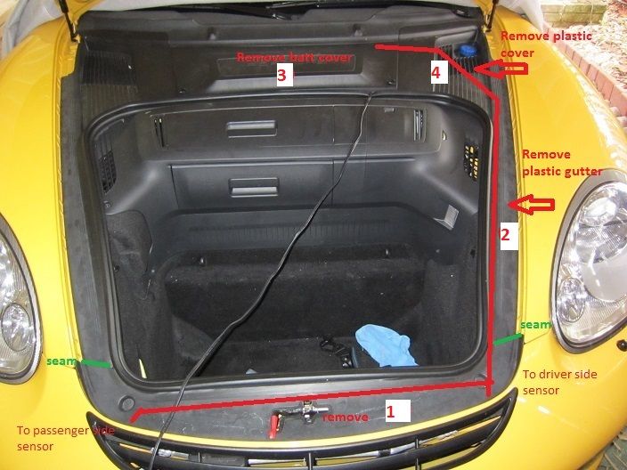
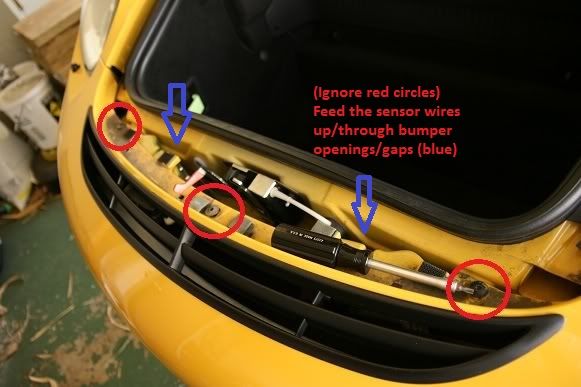
The blue arrow shows where you can pull the wires/plugs up from sensors.
Getting the sensor wires/plugs into the cabin
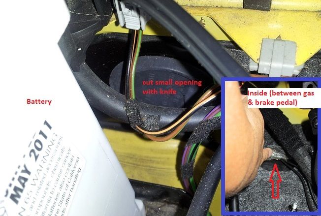
Now that you�ve ran the loom of wires to the firewall (by the way, you should have all the wires (slack/loom) at the firewall, not bunched up at the bumper), you need to get the wires/plugs inside the cabin to the LI CPU. The easiest way is to use an empty rubber grommet located behind the car battery. I suggest you stand inside the front trunk to do this� When you have the batter cover off, you can look behind the car battery and you should see a round (~2� diameter) rubber grommet there. Remove the battery hold-down bracket (passenger side of the battery) with (I believe) a 13mm socket. This allows you to slide the battery towards passenger side. You now should have more room to access that grommet. Take a sharp knife (pointier the better) to cut a cross in the middle of the grommet. You can also remove the grommet from the firewall to cut the hole� just make sure you�re confident you can put the grommet back into the firewall.
Wrap the sensor�s telephone plugs (RJ-11�s) with electrical tape and pass them one at a time through the cut grommet. As you push the wire/plug through, you should go inside cabin and see the wires/plug poke through.
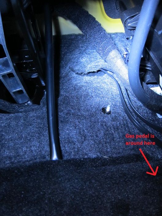
Another picture from inside the cabin � looking up from the driver-side floor. Using a bright flash light to help spot the insulation fabric that�s pre-cut to the size of the grommet. Picture shows the wires coming into the cabin.
Decision time: what to do with the wire slack?
Once the plugs are through, you need to decide whether to pull all the wires (slack) through into the cabin, or only pull what you need. I personally pulled in only what I needed, and left the extra slack outside � under the plastic cover #4 zip-tied in a loom. That way, if I need to remove my bumper and need slack, I can easily get to the slack I need without having to pull all the wires from the cabin.
Wiring up the LI CPU
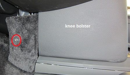
I decided to keep the CPU behind the center console. You need to remove the knee bolster. First remove the torx screw in first picture.
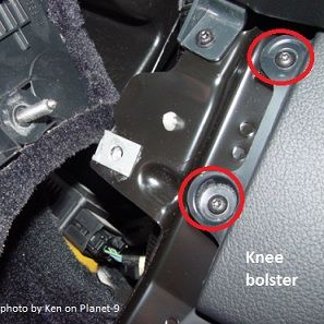
Then remove remvoe the two torx screws.
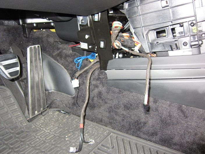
You can run the RJ11 wires and power (+) and ground under the carpet covering the center tunnel. Look for two pieces of Velcro that you can undo to hide these wires out of sight. I use friction tape to all the wire looms tidy.
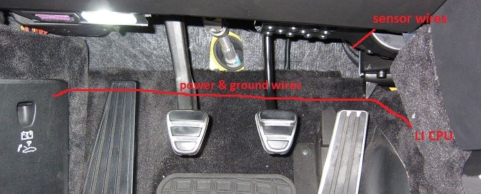
I ran the power & ground wires from the LI connector harness (from behind center console) behind the carpets, all the way around to the fuse panel.
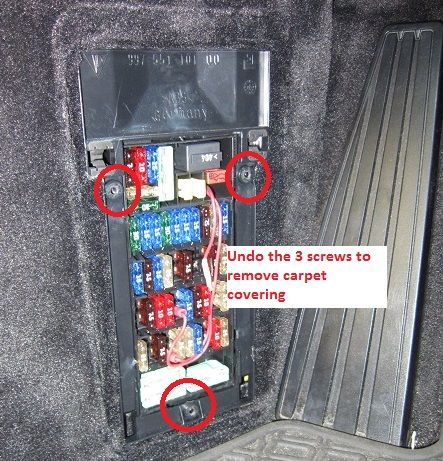
I tapped the power from the fuse panel. I reused the power line for my V1 hardwire. You can access behind the fuse panel by undoing the 3 philips head screws.
Optional - adding visual warning with blinking LED.
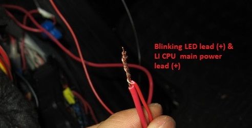
In addition to the built-in speaker, I also added blinking LED to give me a visual warning � for when I have top down or radio turned up. So, I bought a 12v blinking LED from superbrightled.com. I splice the LI and LED power wires together, then tapped into the v1 hardwire line.
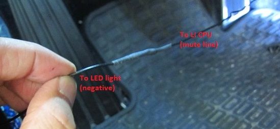
I connected the LED ground wire to the mute line from the LI wire loom harness. The mute line from LI is trigger to ground when the LI alert goes off (activates). So, when LI is triggered (shot with LIDAR), the mute line completes the circuit and LED light blinks, along with the audio warning.
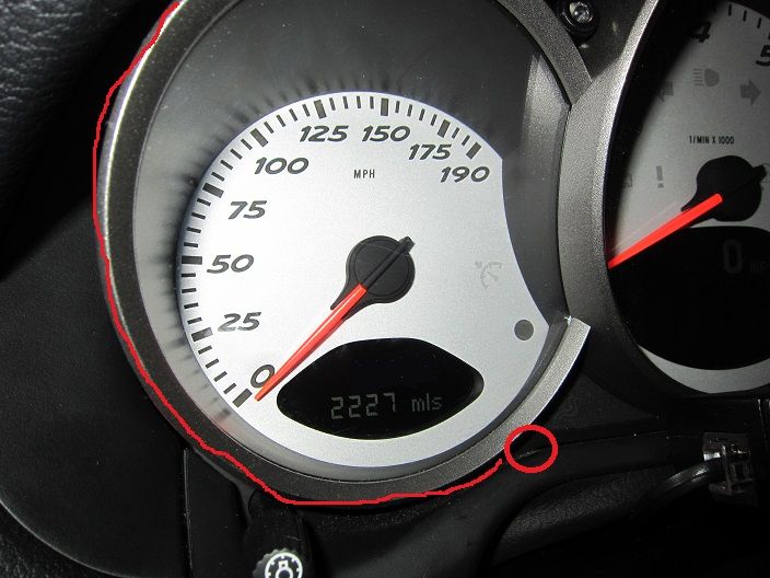
I placed the LED between the speedo and tach � held in-place with 3M tape.
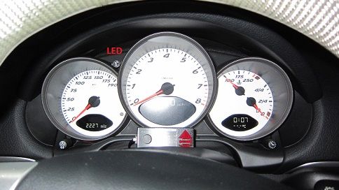
I ran the LED power & ground wires inside a slim slot around the speedo casing, and ran the lines into the dash by prying open a small opening to feed the line through (circled). On the 997�s, you have an additional gauge to left of the speedo, but same idea� you run the lines around that gauge instead.
You can check out how the blinking light warning works here:
http://youtu.be/yvlm_SJcBuc
Power Switch Placement:
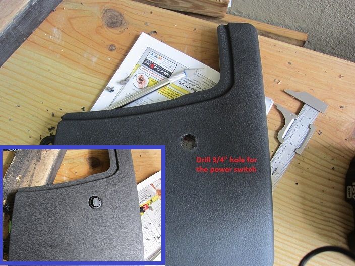
Since you want to quickly turn-off the jammer upon warning (slow down to let the LEO get a speed reading), you want to place the power switch at an easy to reach location. In my car, I decided to put the switch at the knee bolster. This is an easy to reach location with your right hand from a normal driving position � even as you are applying the brakes. Plus, the switch cannot be seen from outside the car.
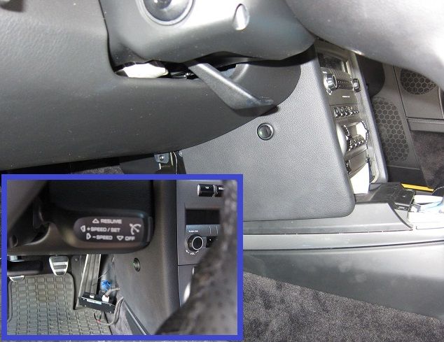
You do need to drill a �� hole to accommodate the switch. And you will need to bend flat the wires at the switch since there isn�t a lot of room behind the bolster. Measure twice, drill once. Start with a small bit and work your way up to ��. Use an xacto knife to cut out some of the vinyl and foam. If you ever need to replace this, the part# is: 997 553 117 01 (or 05). It�s the same part# 987 or 997 and costs about $150.
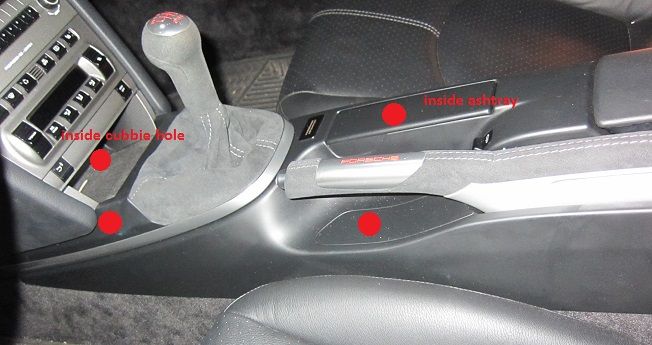
There are a few options for switch placement. Here are some that I considered�
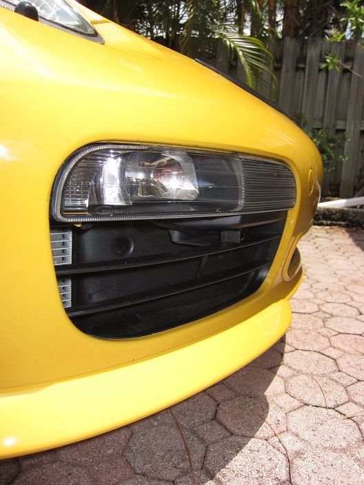
Sensor placement for my car:

You can download the PDF version here:
https://www.box.com/s/089dec34accb6d66be3d
The write up applies to 987 (boxster & cayman), but should also be applicable to the 997 cars - just about all the components I worked with in this guide are from the 997 parts bin (i.e., they have 997 part numbers). This document also assumes you have basic knowledge working with automotive electronics, handy with tools and have standard screw driver and torx bit set. This document also assumes you have thoroughly read the Laser Interceptor manual. Naturally, you can use this doc as guide to install laser jamming equipment from other manufacturers also. I picked LI because it�s been proven to perform above other jamming devices. Of course, do your own research.
LI page: http://www.laser-interceptorusa.com/home.html
Tools you should have handy: screw driver, torx bits, shrink tube, electrical connectors, zip ties, knife, pair of wire stripper, electrical tape. Lots of patience.
Optional parts used in this write-up:
- Blinking red LED with 3� lead � part# LW-BR-12VDC from superbrightled.com
Decide how you wish to mount the sensors � via 3M tape or bracket+fasteners.
This procedure assumes you plan to mount the sensors using 3M super strength molding tape. There are many installs out there using 3M tape. As long as you clean the parts of dirt/grease, the tape should have no problem holding the sensors. If you plan to mount the sensors using metal brackets and other fasteners, you�ll need to remove the bumper. You can download the bumper removal procedure here: https://www.box.com/s/f777a886d1d5d594fb69.
Run sensor wires from bumper to firewall
See picture of the 4 pieces of plastic covers you need to remove. I suggest you remove them in the order I noted. For #1, you simply pull up from either the driver or passenger side seam (green). This piece is fastened by 5 or 6 pieces of Velcro� just pull up and the plastic cover will come off. All the pieces come
off easily. If this is your first time taking the trims apart, I encourage you pay attention to how these come off/out, so you know how to put them back. The red line illustrates where I ran the sensor wires from bumper to the firewall. After you�ve run the wires to the firewall, you can re-install the plastic pieces to cover/conceal the wires from sight.
The blue arrow shows where you can pull the wires/plugs up from sensors.
Getting the sensor wires/plugs into the cabin
Now that you�ve ran the loom of wires to the firewall (by the way, you should have all the wires (slack/loom) at the firewall, not bunched up at the bumper), you need to get the wires/plugs inside the cabin to the LI CPU. The easiest way is to use an empty rubber grommet located behind the car battery. I suggest you stand inside the front trunk to do this� When you have the batter cover off, you can look behind the car battery and you should see a round (~2� diameter) rubber grommet there. Remove the battery hold-down bracket (passenger side of the battery) with (I believe) a 13mm socket. This allows you to slide the battery towards passenger side. You now should have more room to access that grommet. Take a sharp knife (pointier the better) to cut a cross in the middle of the grommet. You can also remove the grommet from the firewall to cut the hole� just make sure you�re confident you can put the grommet back into the firewall.
Wrap the sensor�s telephone plugs (RJ-11�s) with electrical tape and pass them one at a time through the cut grommet. As you push the wire/plug through, you should go inside cabin and see the wires/plug poke through.
Another picture from inside the cabin � looking up from the driver-side floor. Using a bright flash light to help spot the insulation fabric that�s pre-cut to the size of the grommet. Picture shows the wires coming into the cabin.
Decision time: what to do with the wire slack?
Once the plugs are through, you need to decide whether to pull all the wires (slack) through into the cabin, or only pull what you need. I personally pulled in only what I needed, and left the extra slack outside � under the plastic cover #4 zip-tied in a loom. That way, if I need to remove my bumper and need slack, I can easily get to the slack I need without having to pull all the wires from the cabin.
Wiring up the LI CPU
I decided to keep the CPU behind the center console. You need to remove the knee bolster. First remove the torx screw in first picture.
Then remove remvoe the two torx screws.
You can run the RJ11 wires and power (+) and ground under the carpet covering the center tunnel. Look for two pieces of Velcro that you can undo to hide these wires out of sight. I use friction tape to all the wire looms tidy.
I ran the power & ground wires from the LI connector harness (from behind center console) behind the carpets, all the way around to the fuse panel.
I tapped the power from the fuse panel. I reused the power line for my V1 hardwire. You can access behind the fuse panel by undoing the 3 philips head screws.
Optional - adding visual warning with blinking LED.
In addition to the built-in speaker, I also added blinking LED to give me a visual warning � for when I have top down or radio turned up. So, I bought a 12v blinking LED from superbrightled.com. I splice the LI and LED power wires together, then tapped into the v1 hardwire line.
I connected the LED ground wire to the mute line from the LI wire loom harness. The mute line from LI is trigger to ground when the LI alert goes off (activates). So, when LI is triggered (shot with LIDAR), the mute line completes the circuit and LED light blinks, along with the audio warning.
I placed the LED between the speedo and tach � held in-place with 3M tape.
I ran the LED power & ground wires inside a slim slot around the speedo casing, and ran the lines into the dash by prying open a small opening to feed the line through (circled). On the 997�s, you have an additional gauge to left of the speedo, but same idea� you run the lines around that gauge instead.
You can check out how the blinking light warning works here:
http://youtu.be/yvlm_SJcBuc
Power Switch Placement:
Since you want to quickly turn-off the jammer upon warning (slow down to let the LEO get a speed reading), you want to place the power switch at an easy to reach location. In my car, I decided to put the switch at the knee bolster. This is an easy to reach location with your right hand from a normal driving position � even as you are applying the brakes. Plus, the switch cannot be seen from outside the car.
You do need to drill a �� hole to accommodate the switch. And you will need to bend flat the wires at the switch since there isn�t a lot of room behind the bolster. Measure twice, drill once. Start with a small bit and work your way up to ��. Use an xacto knife to cut out some of the vinyl and foam. If you ever need to replace this, the part# is: 997 553 117 01 (or 05). It�s the same part# 987 or 997 and costs about $150.
There are a few options for switch placement. Here are some that I considered�
Sensor placement for my car:
You can download the PDF version here:
https://www.box.com/s/089dec34accb6d66be3d
