When you click on links to various merchants on this site and make a purchase, this can result in this site earning a commission. Affiliate programs and affiliations include, but are not limited to, the eBay Partner Network.
LEAKS! Water Pump, T-Stat, Rear Crossover, Cyl Head Vent
To be honest, my CTT had no leaks. I recently bought the car with 58K miles on the clock and just turned over 60K. So as a preemptive measure and a little mission creep I dove in and took care of all the potential coolant leaks. My thinking behind the project was to take it apart once. So this DIY will cover Disassembly down to the bottom of the V. Then building it back up. Checking the rear crossover pipe, replacing the cylinder head vent tube, JB welding the thermostat housing, installing a new thermostat, installing a new water pump, replacing all the pulleys, serpentine belt, and tensioner.
This won"t be a step by step tutorial but close. I strongly suggest an ALLDATA subscription for this job. I referenced it quite a bit for torque specs, serpentine belt routing, fuel rail tightening sequence and intake manifold tighening sequence. What was most helpful was the pictures I took along the way. Being able to zoom in and look at the way the little hoses were routed and the wiring harnesses were routed was invaluable. It all went back together just the way the factory did it and I didn't make any mistakes.
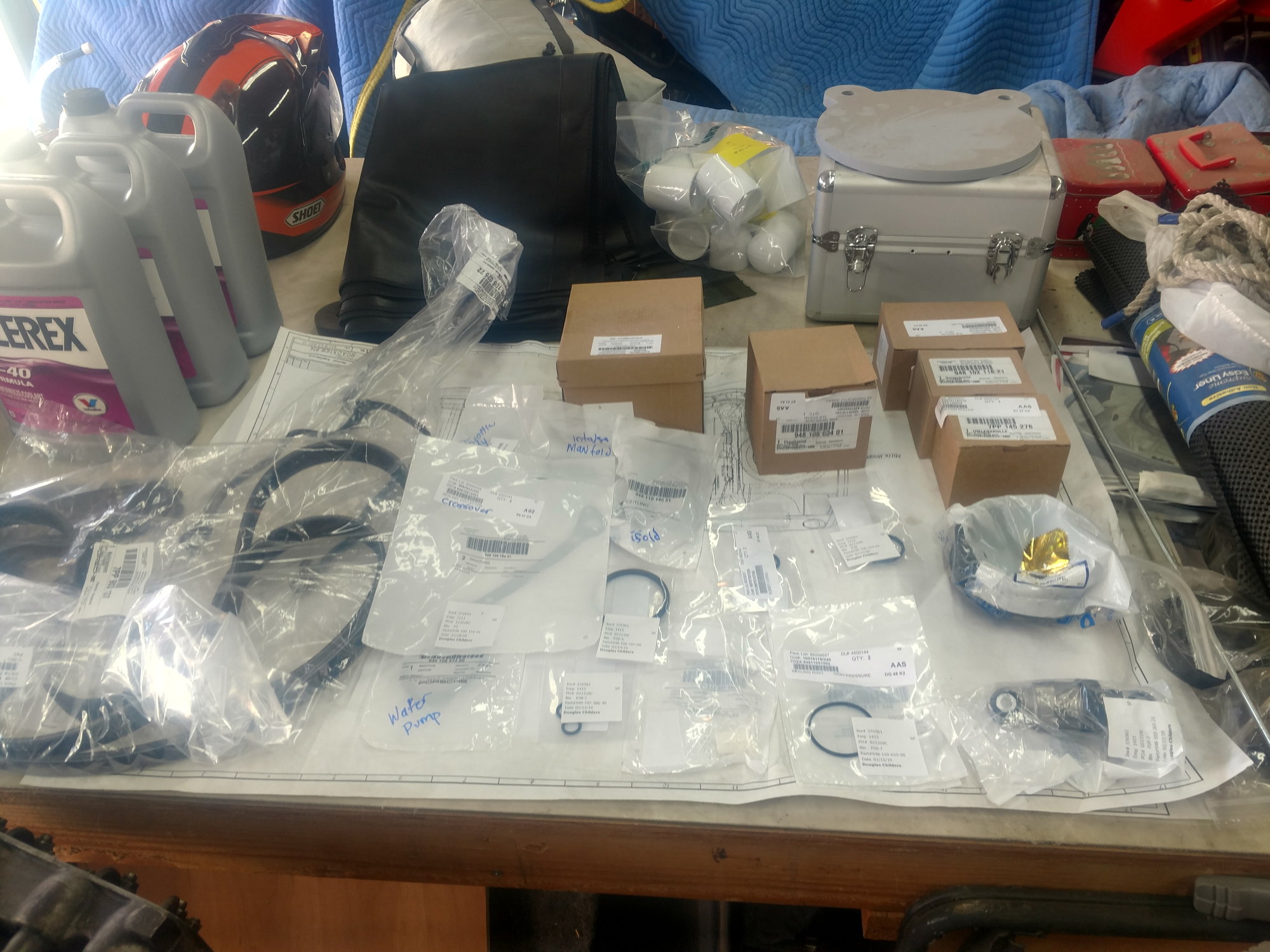
Here is the parts list:
Torque Arm (to replace those single use aluminum bolts and nuts)
1. 1- 10x90x1.25 grade 10.9 flange bolt
2. 1- 10x70x1.25 grade 10.9 flange bolt
3. 2- 10x1.25 flange nuts
Water Pump
1. 1- aluminum water pump pulley URO pn/ 94810609101 2. 1- water pump 948.106.033.01 (comes with gasket) 3. 2- t-stat housing o-rings 948.106.124.02 4. 1- t-stat 948.106.034.03 (comes with o-rings) 5. 2- o-rings for the pipe that comes out of the back of the t-stat housing 999.707.477.40 6. 1- cylinder head vent tube 948.106.026.22 (comes with o-rings)
Serpentine Belt 1. 1- serpentine belt 7PP.903.137 2. 1- tensioner pulley 948.102.403.23 (comes with cap) 3. 1- tensioner 948.102.261.21 4. 1- idler pulley right 948.102.118.21 (comes with cap) 5. 1- idler pulley left 7PP.145.276 (comes with cap)
Intake Manifold 1. 8- intake manifold gaskets 948.110.146.01 2. 1- throttle body o-ring (can't find the number) 3. 1- Y piece to throttle body(can't find the number)
Misc.
1. 2- bottles of Zerex G-40
Tools
1. torx socket set
2. female torx socket set
3. schwaben coolant refill kit
4. female torx wrench set
5. regular metric wrenches and socket set
6. 19mm crows foot
7. screw driver set
8. painters tape (to cover holes)
Lets begin. Again, I suggest taking pictures (different angles) of each step. Especially in the beginning because there are a lot of small hoses that need to be moved around.
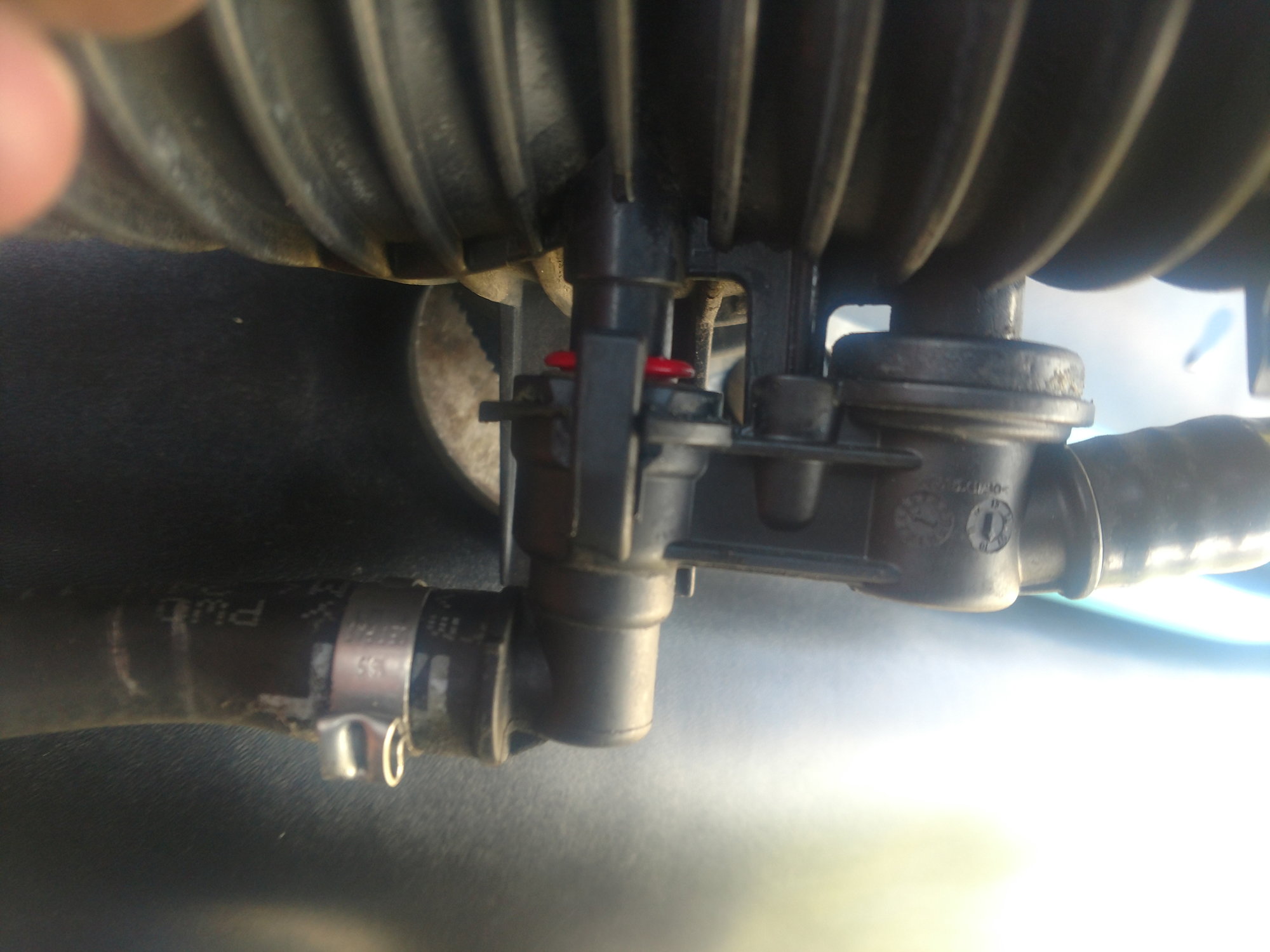
I started with the Y piece. I for the life of me couldn't figure out how to disconnect the fitting on the bottom. This guy....
So I removed it with it intact. I first removed the accordion hoses, then pulled the 1/4 turn pins that hold the Y-piece to the throttle body. There is a hose that comes off the bottom of the funky connector on the bottom of the Y that runs down close to the left valve cover. It connects to a hard line with one of those single use hose clamps. I had to cut that hose clamp off to disconnect it. I replaced it with a regular worm type hose clamp. See the hard line to the left/bottom of the valve cover?
If I remember correctly, I had to roll the Y-piece toward the front of the car to get it off. Pay close attention to the way the small hoses behind the Y are routed and attached to their little holder in there. Lots of pictures from different angles will pay dividends if you want it to go back as the factory had it. Don't count on my pictures.
Y-piece removed
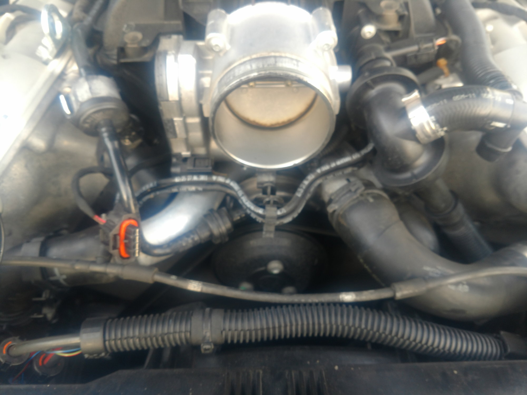
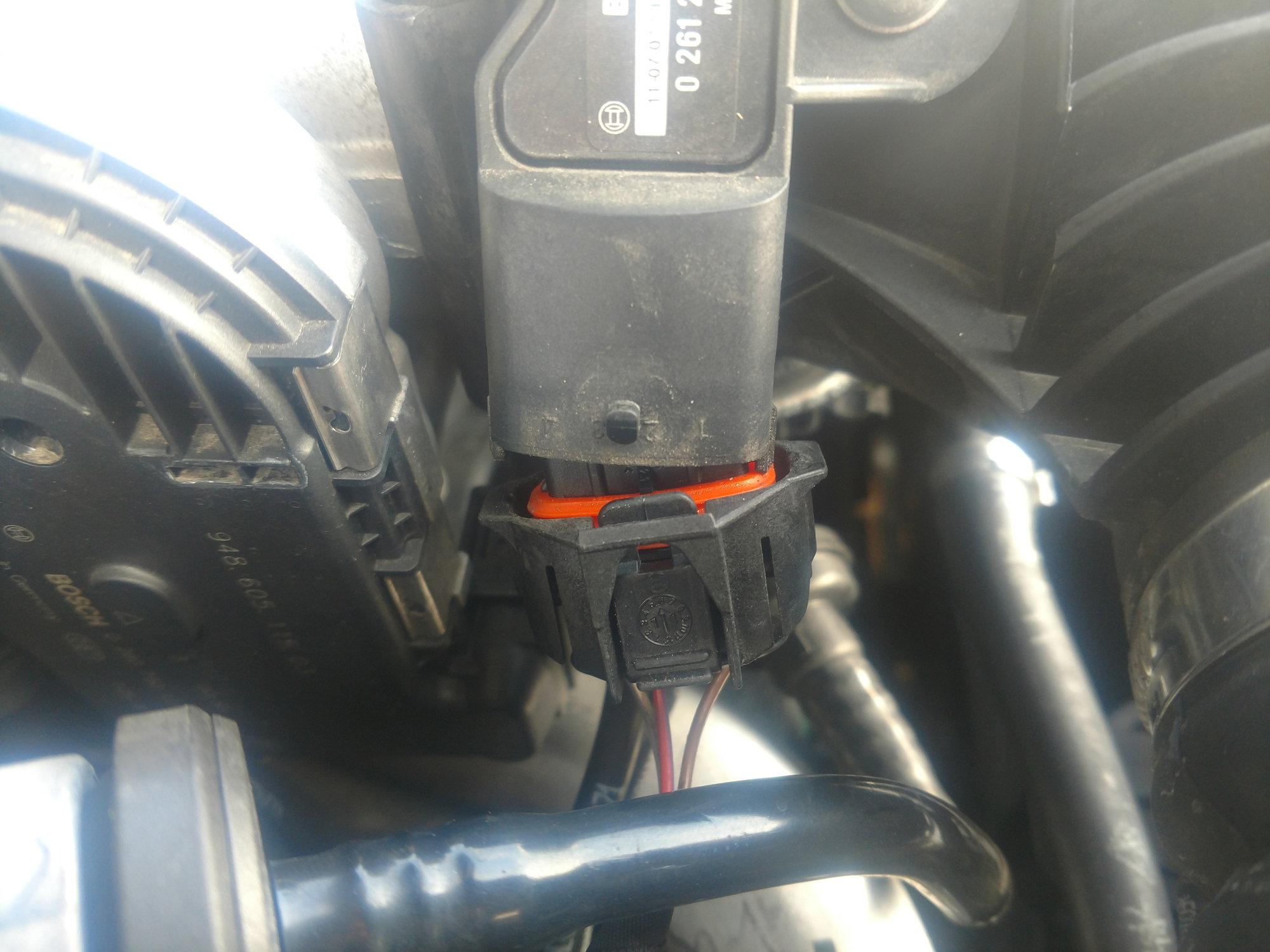
Time to remove the throttle body. First, undo the electrical connector.
Then remove the throttle body. It has long Torx screws. Here it is removed.
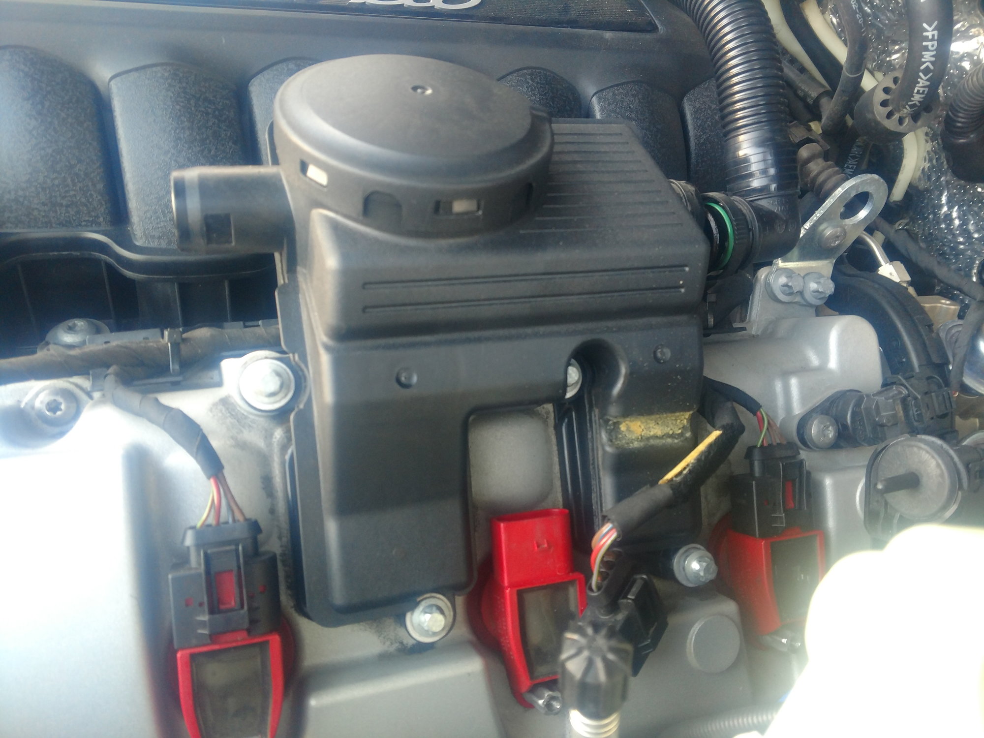
Now you have to remove the oil separator and its hoses. One hose runs to the front of the intake manifold, the PCV valve (I think), and one hose runs down to the right, between the front of the engine and the radiator. They are pretty easy to remove. The hoses have those squeeze connectors that you have to pinch and pull.
The oil separator has to different o-ring/gaskets that get replaced when it goes back on.
Last edited by deilenberger; 04-20-2019 at 10:42 PM.
If you have gotten this far hopefully you have been covering all of your open holes with your painters tape. Chances are your engine is dirty and you don't want any dust or dirt falling into places it shouldn't. I use painters tape for the flat surfaces and for open hoses i use sandwich baggies with a rubber band over the open hoses.
We are getting close to removing the intake manifold. At the base of the manifold on the passenger side, there is a hose with a valve on the end of it that needs to be removed. For those that don't know, it's the valve that goes clackity clack. If you haven't seen it I'm sure you've heard it. If I remember correctly the valve is held on with a rubber isolator. Just pull it straight up off of its support. The other end of the pipe is held together with one of those pinch quick disconnects. Sorry, I didn't get a photo of this pipe but you can't miss it. You can't get to the intake manifold bolts with it in place.
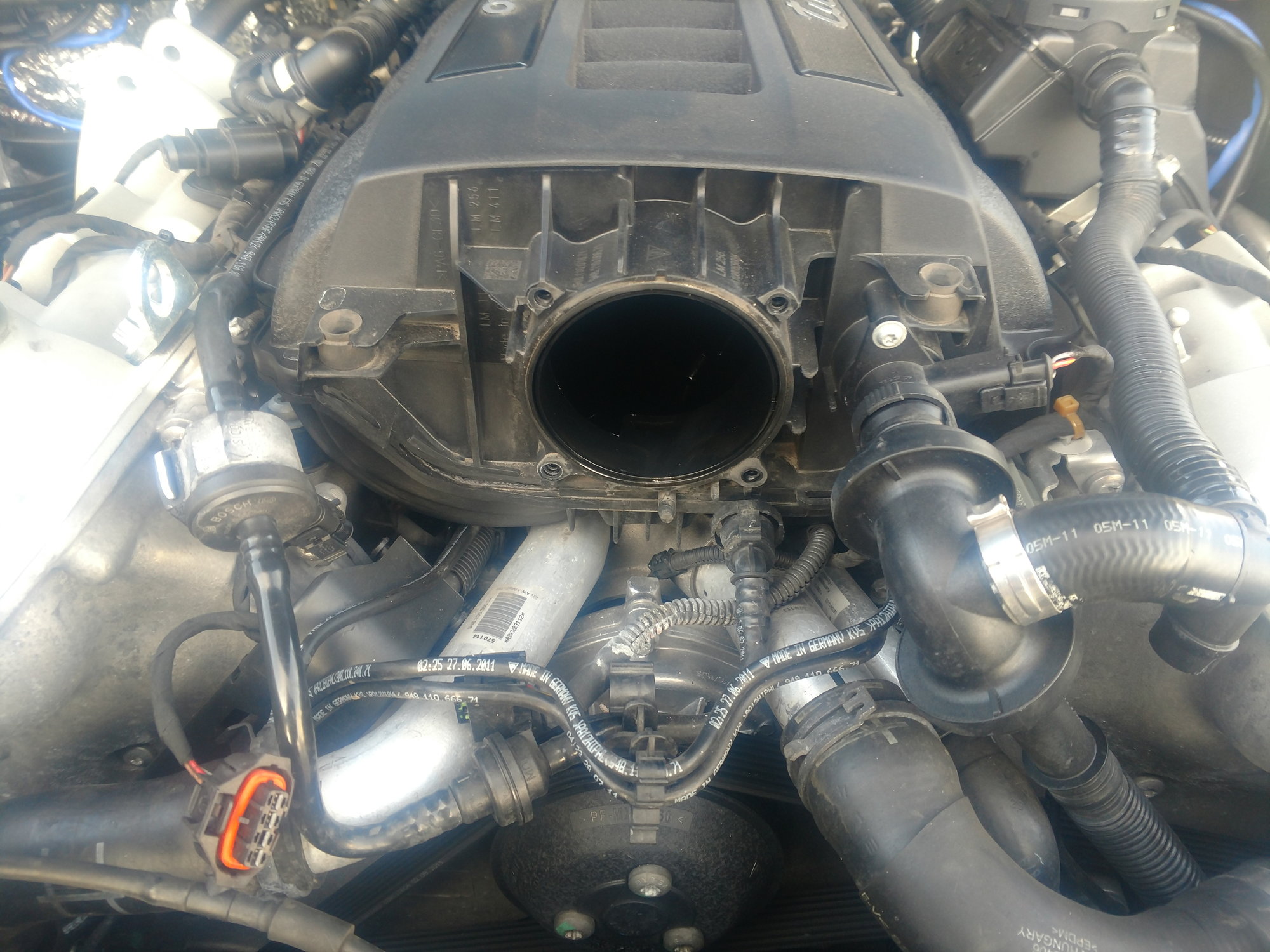
Now you can prep for the manifold removal. On the back of the manifold, about halfway up, right in the middle of it is a small U shaped hose. It's a little guy and has NO kind of clamp. It simply pulls off. There is also one electrical connector on the manifold that needs to be undone. It is on the driver's side, in the back, near the base of the manifold. The manifold should be ready for removal now. This is what I did. There are 10 bolts I believe, that hold the manifold down. I looked up the tightening sequence on alldata and loosened the bolts in that sequence. I also loosened them a little at a time. Maybe a quarter turn each until they were all well loose. this might be overkill but my thinking for loosening the bolts this way was to keep any distortion to the mating surface to a minimum. And it worked. It surely didn't hurt. The manifold base bolts are held captive and won't come completely out. Then just lift the manifold straight up and pull it out. Make sure you lift it up far enough that those captive bolts don't drag across the mating surfaces. It would suck to put a big scratch across the mating surfaces.
And waalaa,
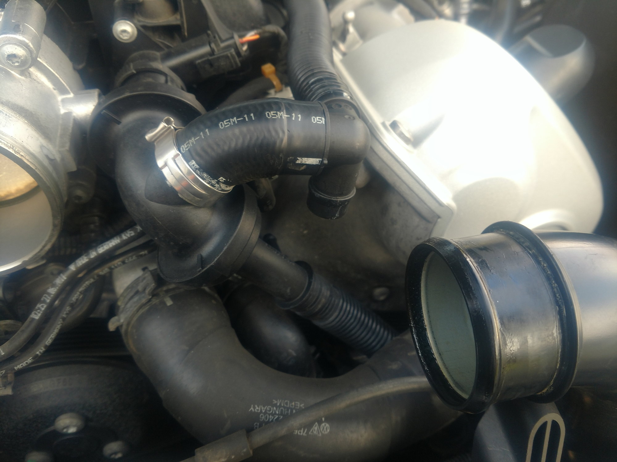
My next step was to pull the radiator hoses and drain the coolant. You're going to need something to catch the coolant under the car. It's going to be a bit messy so it is what it is. Starting with the drivers side of radiator pull the connector that holds the hose to the radiator and let it dump.(you should have a couple of open hoses down there between the fans and engine so bag and rubber band them so you don't get any coolant in them) on the other end pull the spring clip back and twist the hose off the t-stat housing. The other big hose I just removed the t-stat end and folded it back towards the passenger side air filter box.
In between and below the two aluminum pipes are the water pump and the actual t-stat. That wire and connector are attached to the actual t-stat. Detach the electrical connector.
At this point, I switched gears and worked on the back of the engine. I fully intended to remove the back crossover pipe and JB weld the glued pipe. I removed the high-pressure fuel pump and was able to get a good look the crossover pipe and low and behold my car was fitted with the updated version WHEW! What a relief it was to see that. Because I truly didn't know how I was going to get it out of there. We talked about it in another thread a none of the options were good short of removing the engine.
The firewall wall that is behind the engine is actually a false firewall that is removable. Just removing that false firewall would be a major project in itself. The next option would be to repair it in place, which has its own DIY already. But one option I didn't explore was going through the fender wells. When I found out I had the updated version, I let out a big sigh of relief and stopped there. Removing the high-pressure fuel pump was not necessary in my case but I will go through the steps anyway. Because If you do have to repair or replace that crossover tube the HPFP will have to come out anyways. That will be tomorrow nights project.
Last edited by deilenberger; 04-20-2019 at 10:47 PM.
Are you guys still with me? I know this looks like a daunting task, but it's really not. It's just nuts and bolts. The way I see it is.... I know a man put it together, so I can take it apart and put it back together. I have two hands just like him. And up to this point I think I'm about four hours into it. I think it took just as long stopping for pictures and bagging and tagging all my nuts and bolts I took off.
So lets take apart the fuel system. ALLDATA does a pretty good job detailing how to take off the high-pressure fuel pump so I will just hit the highlights.
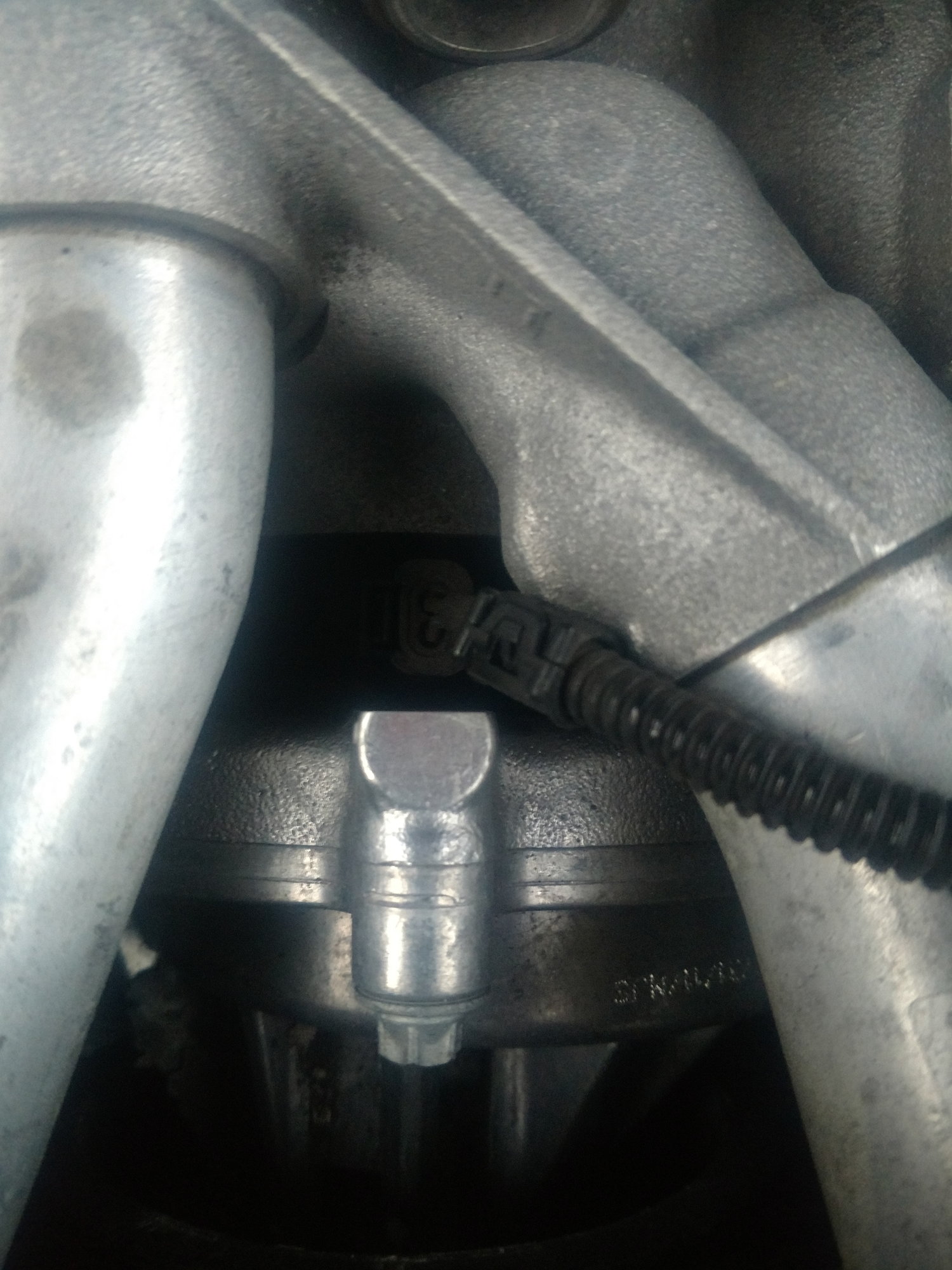
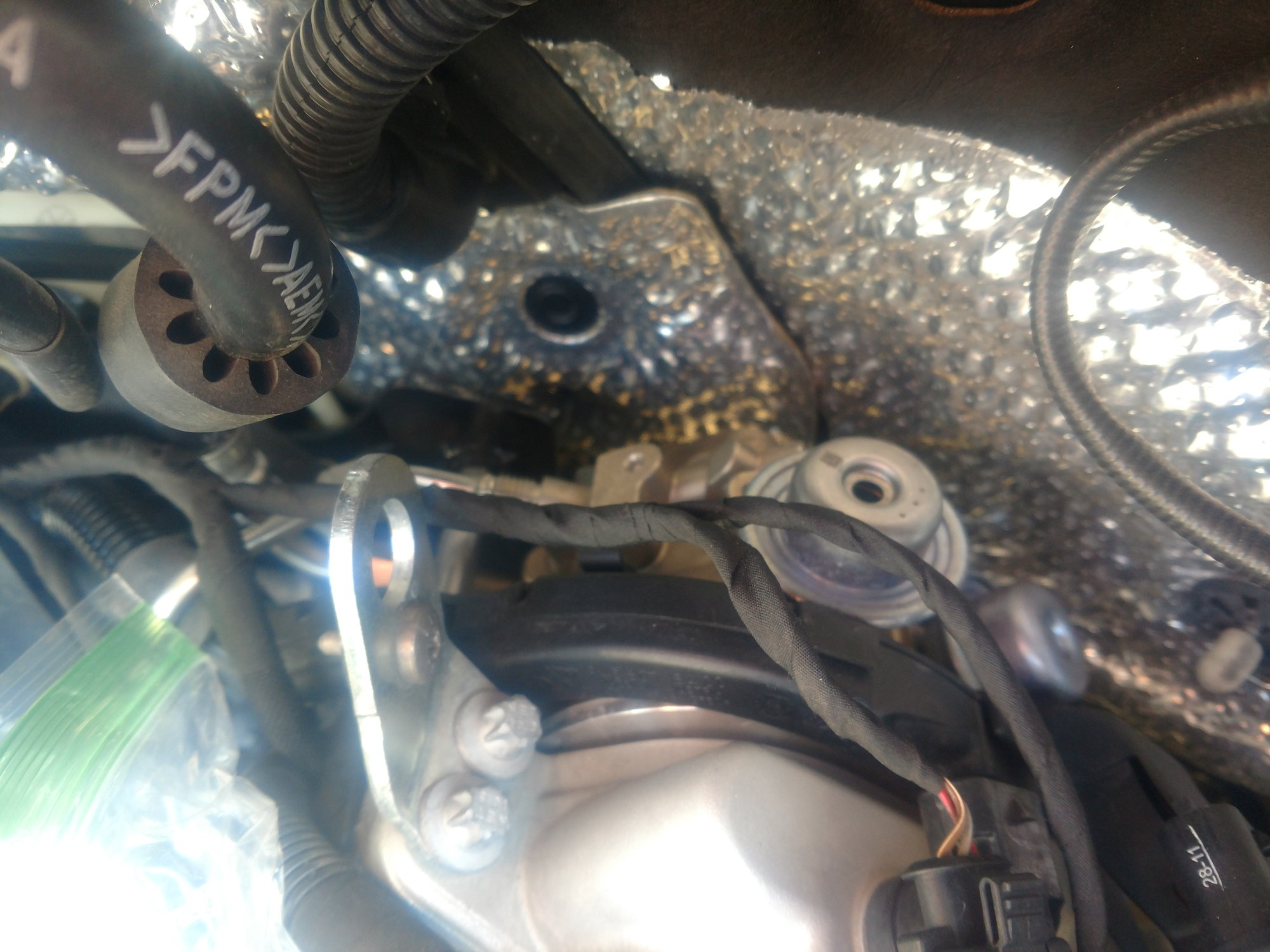
The HPFP is on the drivers rear end of the cylinder head. It's the thing with the little dash pot looking thing on it in the picture. There is a small wire harness that runs across the top of it so you will have to unplug the connectors and move the harness out of the way.
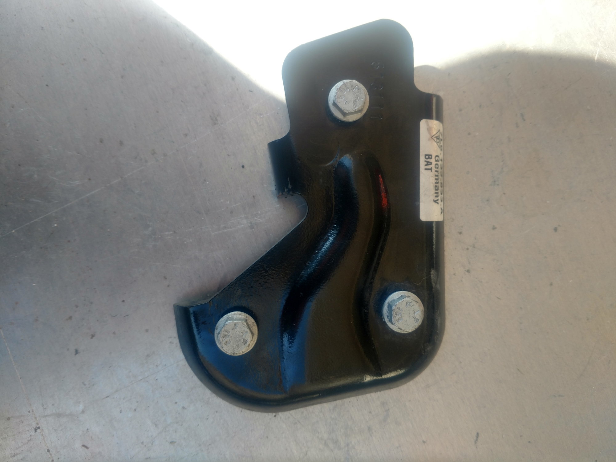
On the back of the pump itself is a metal crash plate. That will be the first thing that needs to be removed. This job is done from under the car. There are three bolts that have to be removed to get the plate off. The bolts actually thread into long hexagonal shafts that hold the fuel pump to the head. So with the crash plate removed the fuel pump will still be attached to the head. Not until you remove the hexagonal shafts will the fuel pump actually be free from the head. We will get to that later.
I'm not gonna lie. Removing the crash plate sucks. This is one of those jobs that has to be done by feel. I have a 10mm ratcheting wrench that was really helpful.
Once the plate is removed I recommend undoing the fuel lines before actually loosening the pump from the head. Once the fuel lines are loose go ahead and remove the two long hex bolts and the one regular bolt that is underneath the fuel pump. push the fuel pump back toward the firewall and lift it up so you can undo the electrical connector. Once the connector is undone you can rotate the pump and remove it from the car.
Now stick your finger in the hole the fuel pump shaft just came out of and feel for a broken piece of plastic. If it's not broken you just saved yourself 70 bucks. There is a small plastic piece in that hole that Porsche calls the "stopper". it holds a cog type thing that is the interface between the camshaft and the HPFP shaft. I had a "stopper" on hand but didn't have to use so I returned it. You are gonna crap yourself when you see what your 70 dollars get you..... Anyways, you're probably wondering about that 3rd hexagonal shaft that's in that area. That holds the bracket for the fuel rail. go ahead and remove it because the fuel rail is next. let me get these pictures of the fuel pump and crash plate up before I get too far ahead.....
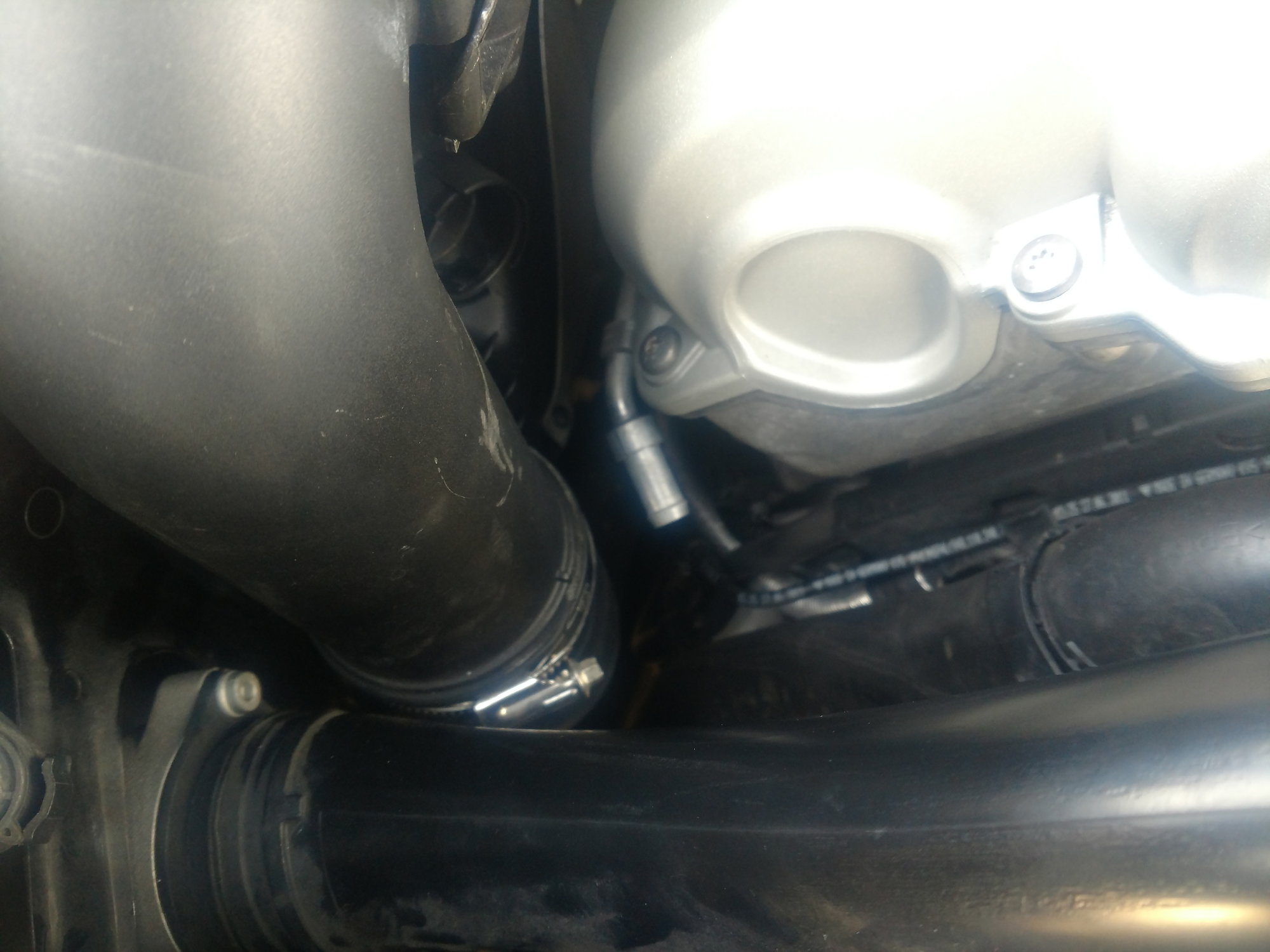
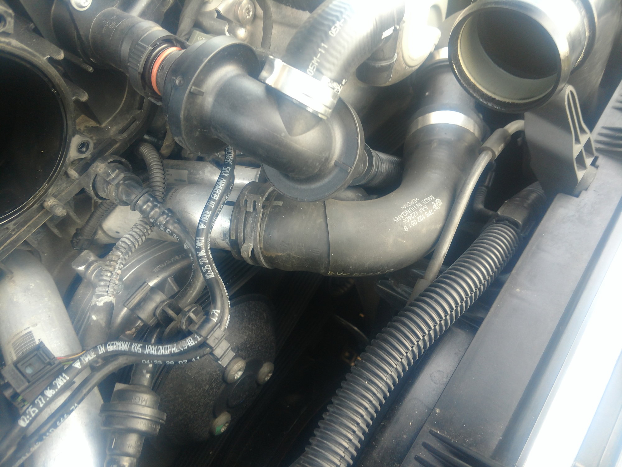
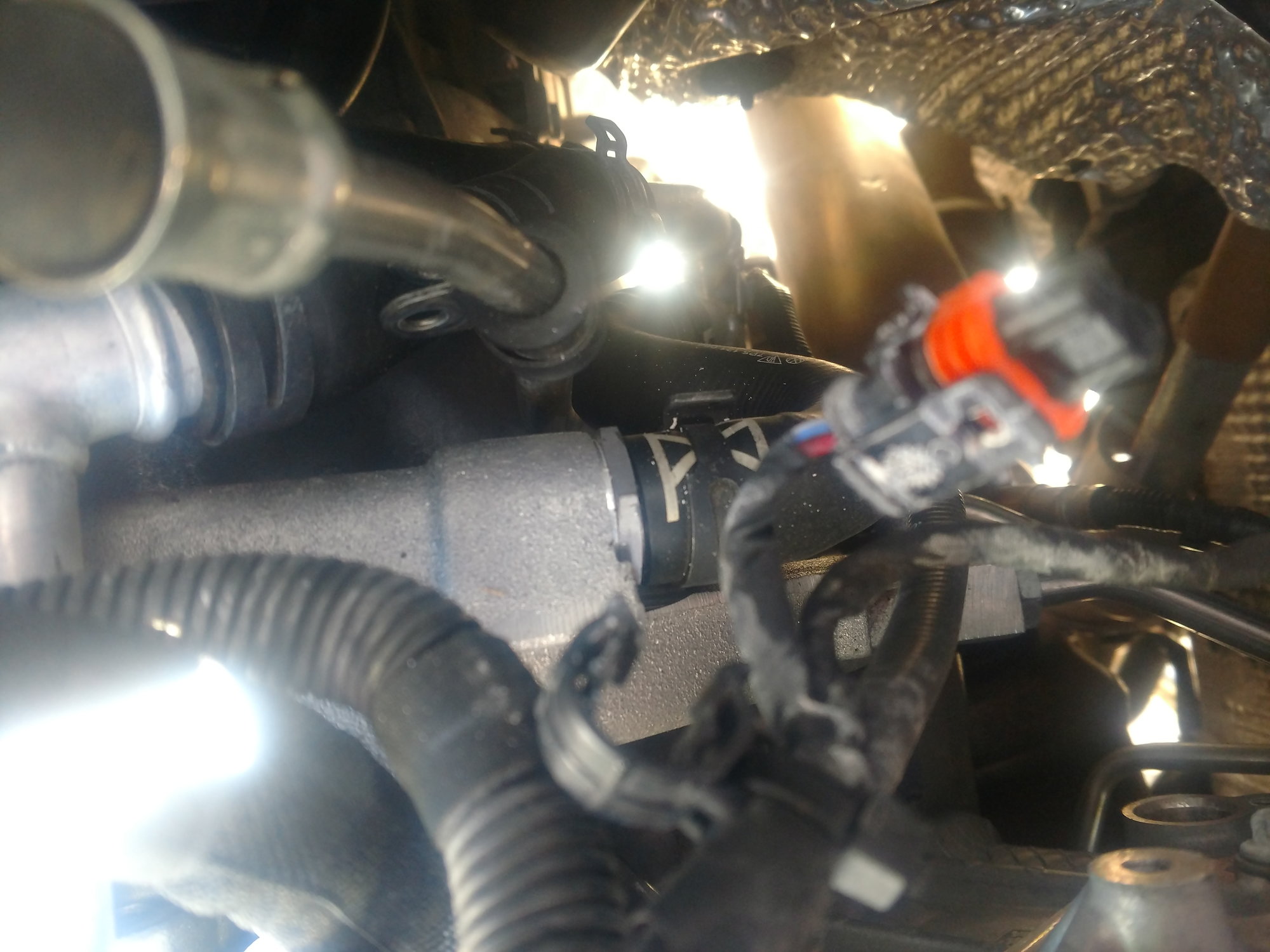
I need to back up. At this point, I could get a good view of the crossover pipe. And this is the point where I was going to have to make a decision. Leave it as is, remember mine wasn't leaking. or spend a WHOLE extra day fighting to get it out of there. At this time I hadn't thought of going through the fender well.
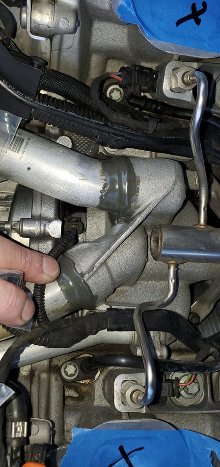
I consider myself an average backyard mechanic and was pretty worried that I was going to have to abandon this part of the project. Some of you may remember my frantic post about the crossover pipe while I having my little crisis. Come to find out my crossover pipe was the updated version as you can see from the picture. If you look at the photo where the bigger black pipe makes its connection, it looks like it connects to a big aluminum hex nut. That is the threaded nipple that threads into the cast crossover pipe.
No famous glued in pipe.
Now.... our fantastic moderator thinks that it may have been updated after the fact. And he may be right. But this car has never had any work done outside of a Porsche dealership and I have all the service records and there is no mention of this being complained about or repaired. And if someone DID replace it, well I would like to meet the man because he is a magician. He didn't break a single tie wrap, or leave any dents or scratches in that textured heat shield, or greasy fingerprints anywhere. I don't care if it came from the factory updated or if someone else did the work. I know it was already done and I didn't have to deal with it.
Hears a picture of what I saw.
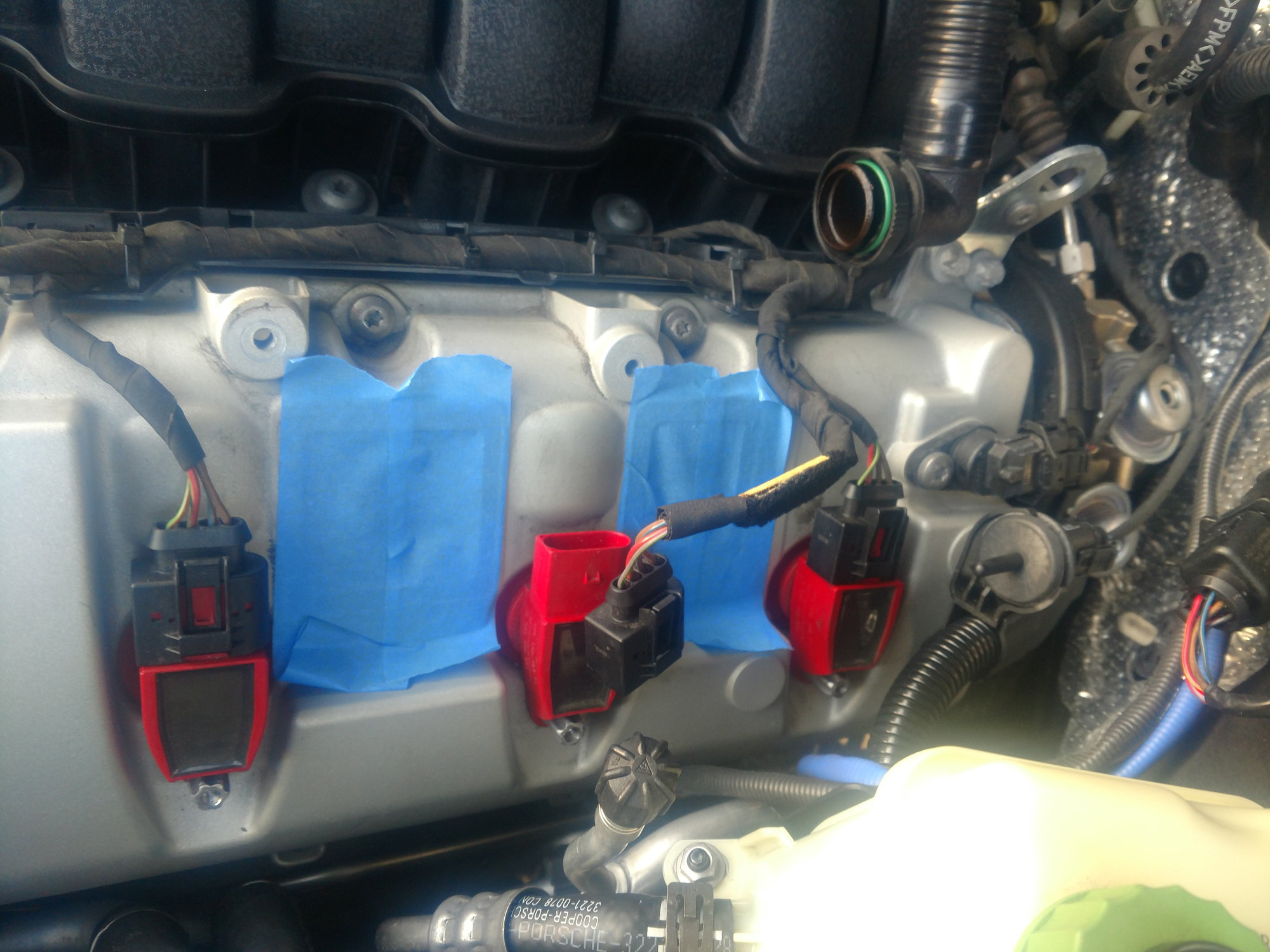
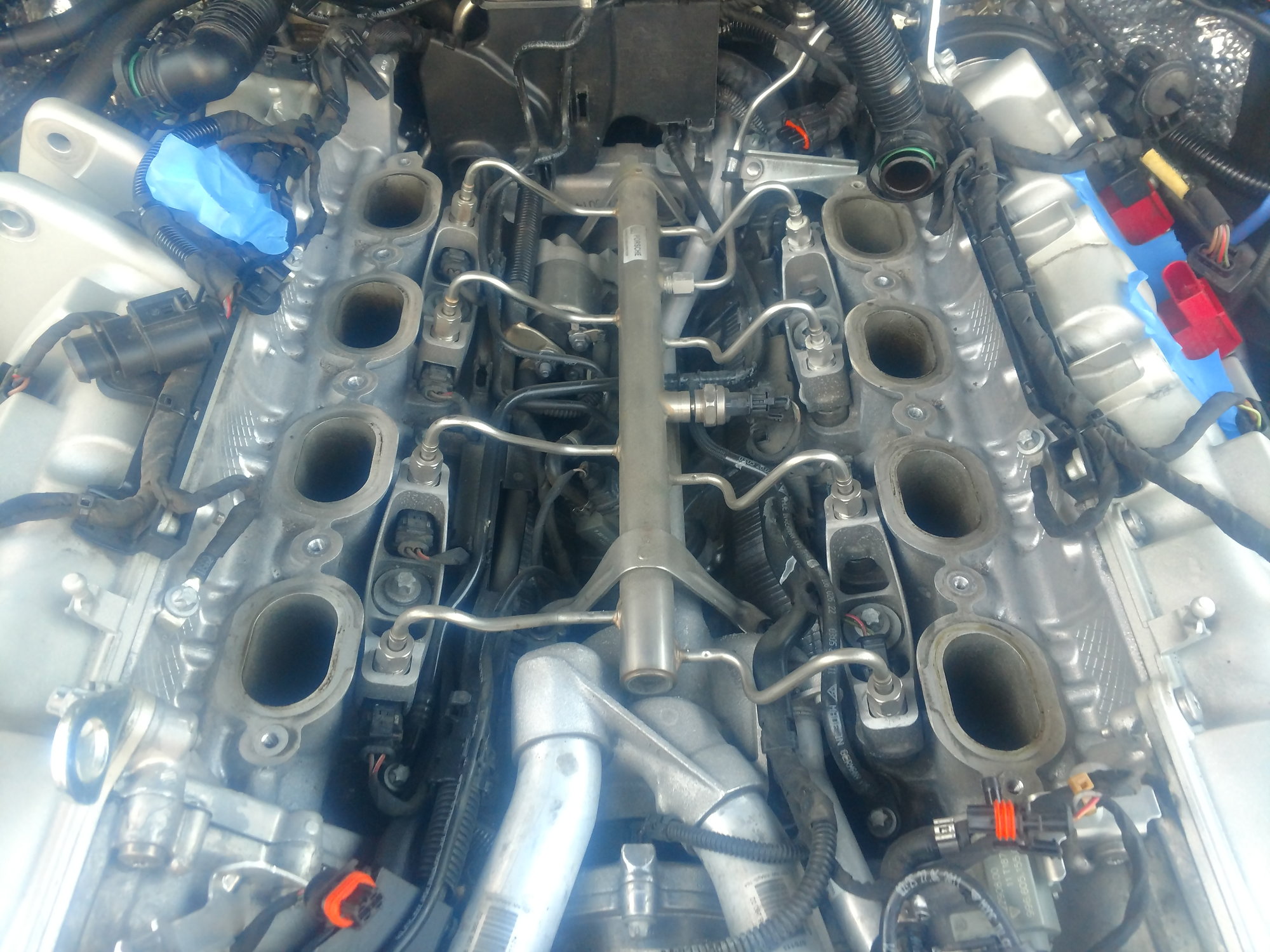
Let's remove the fuel rail. It's the stainless steel spider looking thing.
First thing. Undo the electrical connector. Then take your 19mm wrench and loosen all 8 of the fittings. Make sure they are all completely unscrewed. They should be free to slide up and down the pipe they connect. The feed is already free. You undid it from the HPFP. If you chose not to remove the HPFP then undo the feed now.
There are four Torx screws that hold the spider to the block. The front two are easy. The rear two are not bad either but more care has to be taken. I needed a long extension to get them. And had to climb on top of the engine.
You are taping up and plugging all your open hole I hope. Don't drop either of those rear screws. Ask me how I know. They will fall right in the V under the starter. I didn't drop any during removal but I dropped the passenger rear bolt twice. It took me a half hour each time to get them out each time. Not fun. The good thing is they are steel. So I wised up and took a neodymium magnet and put it on the extension and that held the screw to my socket. Next time I will use this method when taking the screws out.
I got lucky during the removal. Not so lucky on the install.
Anyways, the fuel rail is totally free but your thinking, how the hell do I get it out of there. It's easy. While lifting it up, rotate it 90 degrees while lifting and it comes right out. ALLDATA shows this technique also. Of course, I didn't see it until I had already installed it and was looking for the torque specs. At this point STOP! Tape, bag, do whatever you have to do to cover those injector holes.
We are finally to the bottom of the V. Tomorrow we finally get to do what we have done all this work for. Correct Porsche's mistake.
Last edited by deilenberger; 04-20-2019 at 11:27 PM.
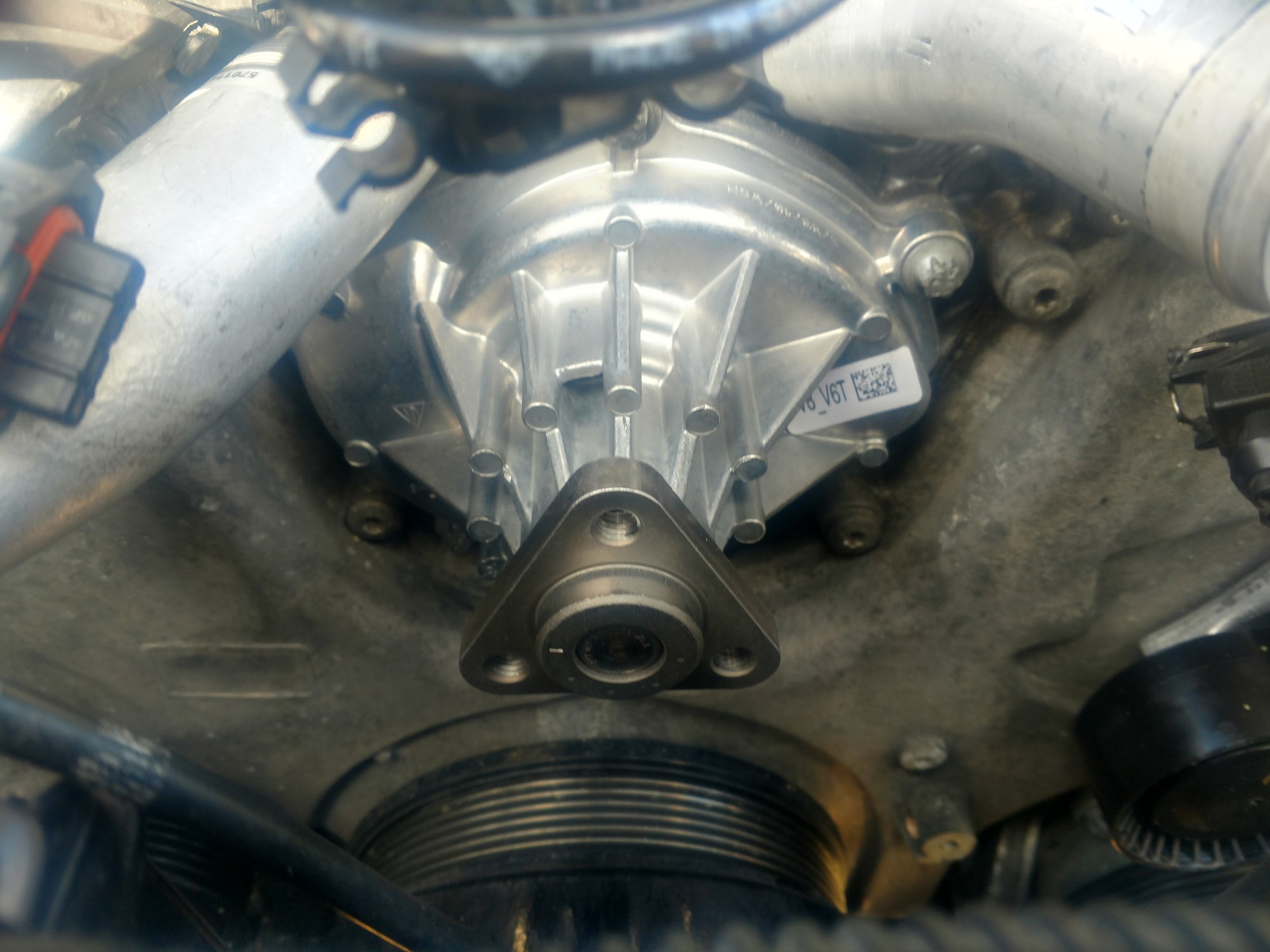
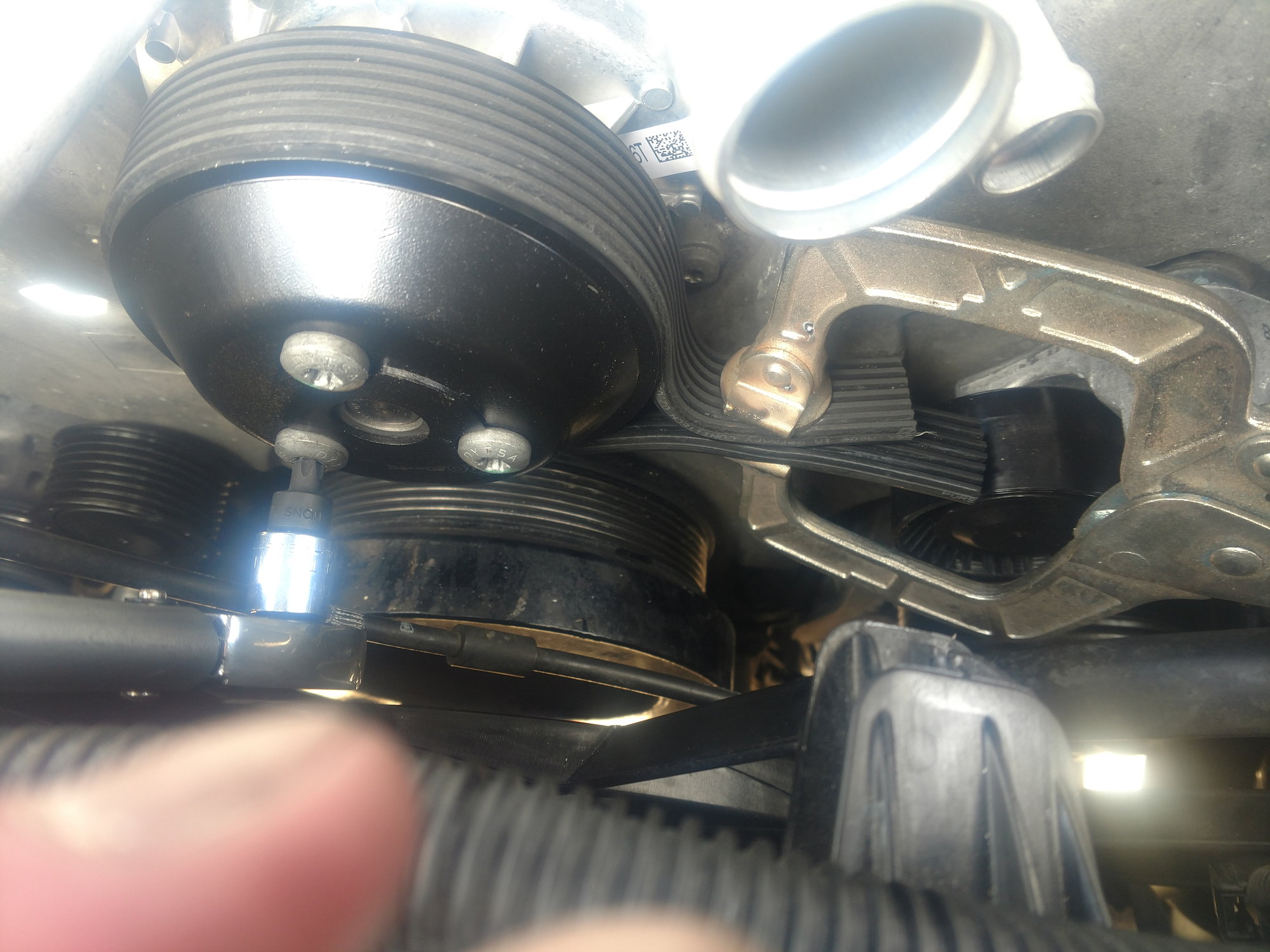
It's time to remove the water pump, thermostat, and thermostat housing. The first thing we need to do is loosen the bolts holding the water pump pulley on. It should be fairly easy with the serpentine belt still under tension.
Once they are loose, grab your 30mm wrench and lever the tensioner over and remove the serpentine belt.
Now remove the WP pulley. I checked the water pump torque sequence on alldata so I would know how to loosen the bolts. To my surprise, it's not a star sequence. It is a clockwise or anti-clockwise sequence. I don't remember. So again, I loosened the bolts a little at a time going around the horn until they were all loose enough to remove by hand.
Put your catch basin under the front of the engine because the next step is going to create a pink waterfall of coolant.
Make sure you didn't miss any of the water pump bolts, grab your soft mallet and give the pump a tap. Mine came right off.
After the pink splash, you should see the black t-stat. My t-stat was stuck in there pretty good. I had to lever it out with an angled pry bar. I used the plastic protrusion that the electrical connection plugs into as a pry point. That's really the only exposed pry point on it. And be careful what you use as a fulcrum. Seems like I remember only one or two choices for the fulcrum.
I didn't want to bend or cave in the T-stat tubes because I am fixing my T-stat housing not replacing it.
I planned to replace my t-stat from day one so I had a brand new one on hand. It's a good thing because I broke the electrical connector while I was levering. Be careful while levering. That little plastic electrical nub is the only thing between you keeping your workflow going. If you break it without removing the t-stat you are in for a really long day. So, if you start to pry and it won't budge, try a different angle. Once you get it moving the resistance will be less and less until you get the second pink wave.
Success. You can remove the t-stat housing now. It is held down by four bolts. One of which you have already removed when you removed the fuel rail. So that one is a freebie. The passenger side bolts were covered by a wiring harness.
At this point, I wish I had a female Torx wrench set.
So I had to remove a few brackets in order to move the harness in order to get at the bolts. I now have a female Torx wrench set (after the fact of course).
I tried to remove the housing without disturbing the pipe that runs into the back of it but it wasn't going to happen. If you follow the pipe to the back of the engine you will see it is held in place by two bolts. one comes right out. the other I just had to loosen. Good thing all I had to do was loosen the second bolt because it would have been a booger to remove.
Anyways, now that you have created a little wiggle room the t-stat house will come right out. The pipe in the back of the housing has two o-rings on the end that plugs into the back of the housing. They are included in the parts list. As well as the o-rings that are under the housing that feeds coolant to the block. Unfortunately, the parts diagram only showed one of each so that all I had. So I had to reuse mine. They were still in good shape otherwise I would have ordered new ones.
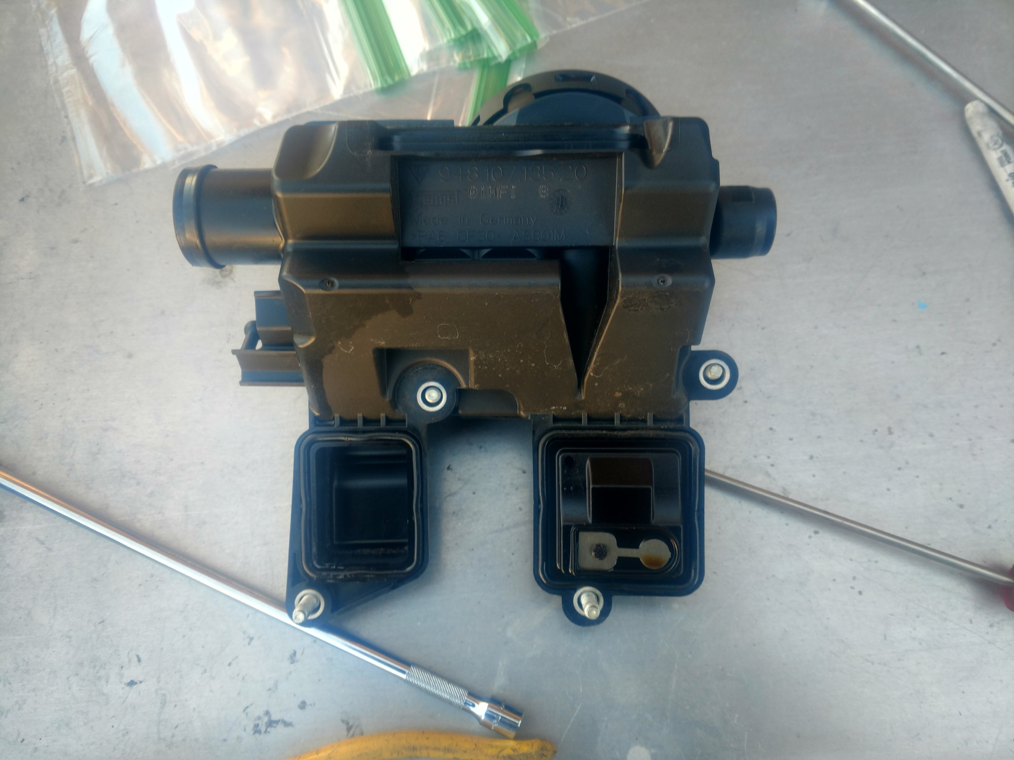
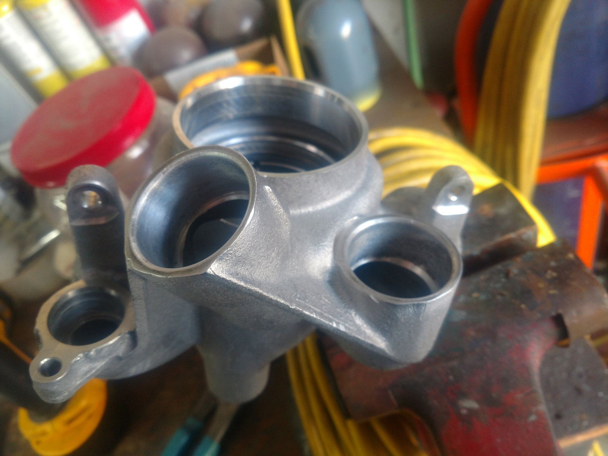
Let's tackle the t-stat housing repair.
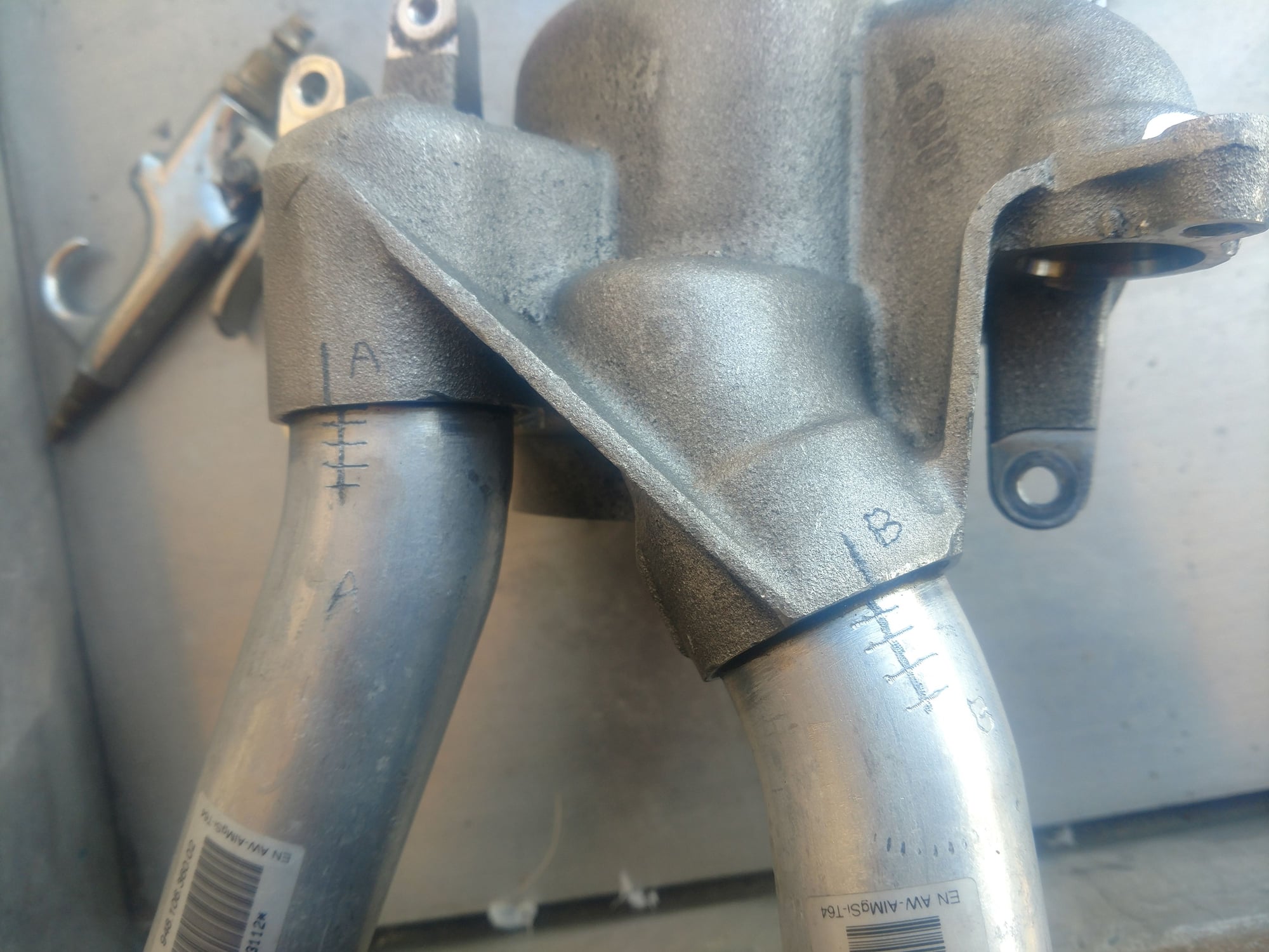
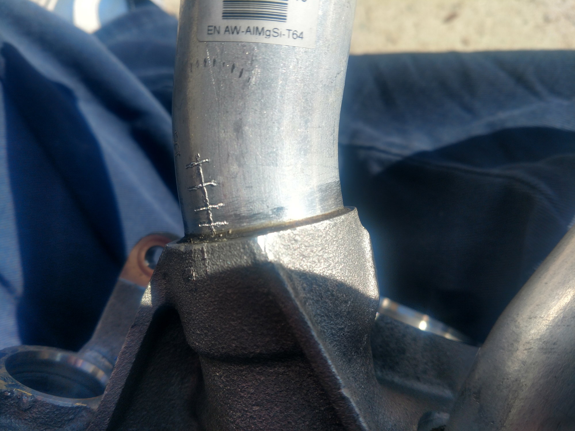
Not knowing what I was up against I took my electric pencil and drew alignment marks to make sure I got the clocking correct and witness marks to make sure I pushed the tubes in deep enough. I also marked them A and B because they are different.
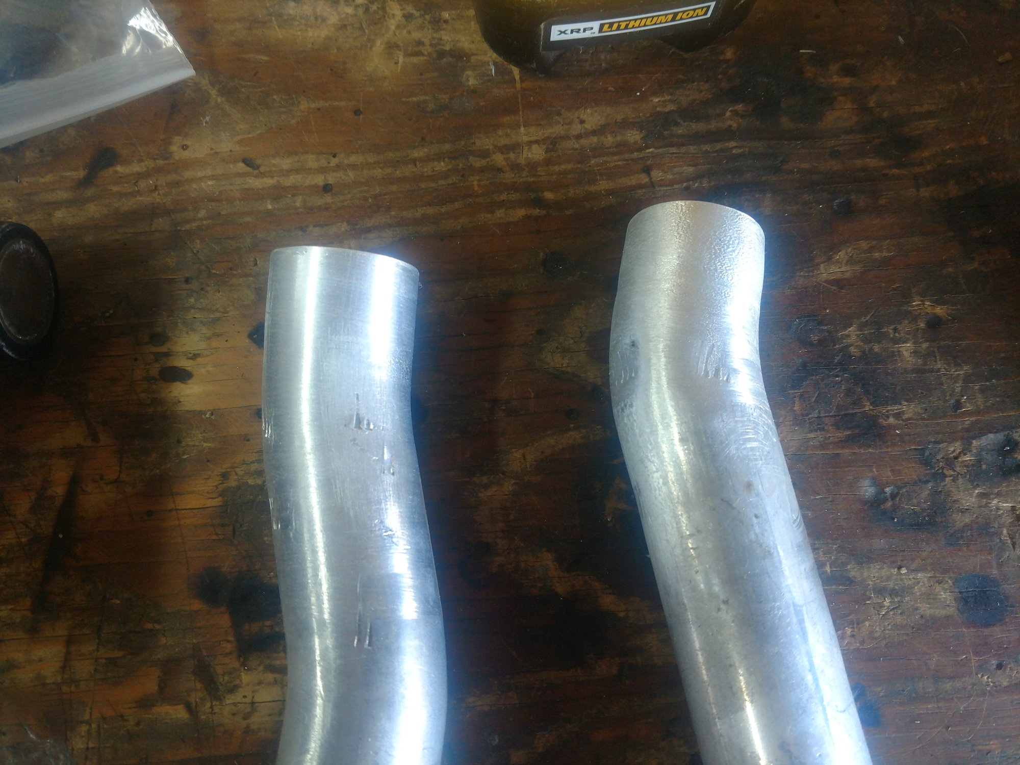
At his point, I clamped the housing into my bench vice and put the fire to it. I used a Mapp gas torch. It took way more heat than I thought it would. I removed mine one at a time. It wasn't until the glue actually started smoking would the pipes start to move. I twisted and pulled at the same time with a pair of channel locks and removed them. I had glue on the inside of the ports and the outside of the pipes. I was able to use my razor knife on the outside of the pipe to remove a big part of the glue and used 100 grit cloth sanding strips to remove the rest. same with the ports. I just used the sanding strips on the ports. no razor knife.
For this to work, I knew it was important to remove every trace of the old glue and to have everything perfectly clean for the JBweld.
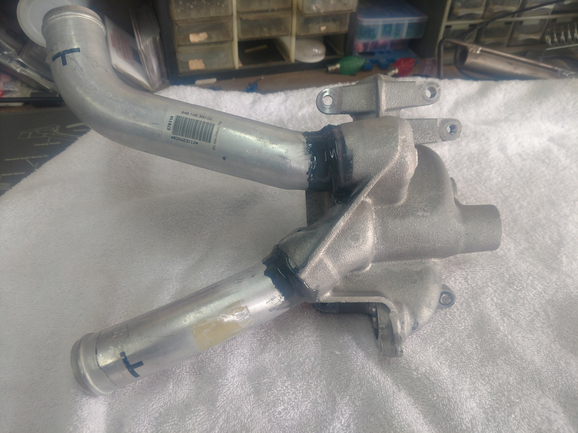
Satisfied that everything was clean I mixed up a batch of JBweld and glued the pipes into the housing. I used a tongue depressor to mix up the JBweld and used it to spread the JBweld around the inside of the socket as well as the outside of the pipe. I didn't want to take any chances of getting an air pocket or a place where coolant could sneak past.
My method paid off. My pipes bottomed out and they were clocked perfectly. After the bonding it was a perfect stopping point for day one. I brought the t=stat housing in the house to dry overnight. I propped it up on the kitchen table and did not disturb it.
Last edited by deilenberger; 04-20-2019 at 11:37 PM.
Looking good. One trick I read somewhere for the thermostat - might have been the factory manual - apparently you can get a wire around a bit of it and then use the wire with a lever to wiggle it out.. at least that's what it said and showed. If I stumble across that I'll put up a link to it or some pics here.
Looking good. One trick I read somewhere for the thermostat - might have been the factory manual - apparently you can get a wire around a bit of it and then use the wire with a lever to wiggle it out.. at least that's what it said and showed. If I stumble across that I'll put up a link to it or some pics here.
The wire trick is how I removed mine when I did it. It still takes quite a bit of pull to break it loose so I used a pry bar in the wire loop to add some oomph to it. The trick is to get the loop the right length to work with the limited locations that can by used to rest the pry bar.
Thanks for the wire trick you guys. I didn't know anything about it. And I probably wouldn't have thought about it if my way failed. I appreciate all the tips and tricks that you guys have. So if you see an easier, faster, better way please post your ideas. If this makes it to the diy section I have given our moderator full permission to slice, dice, cut, and paste. What ever it takes to make it so us gear heads can tackle these tasks on our own.
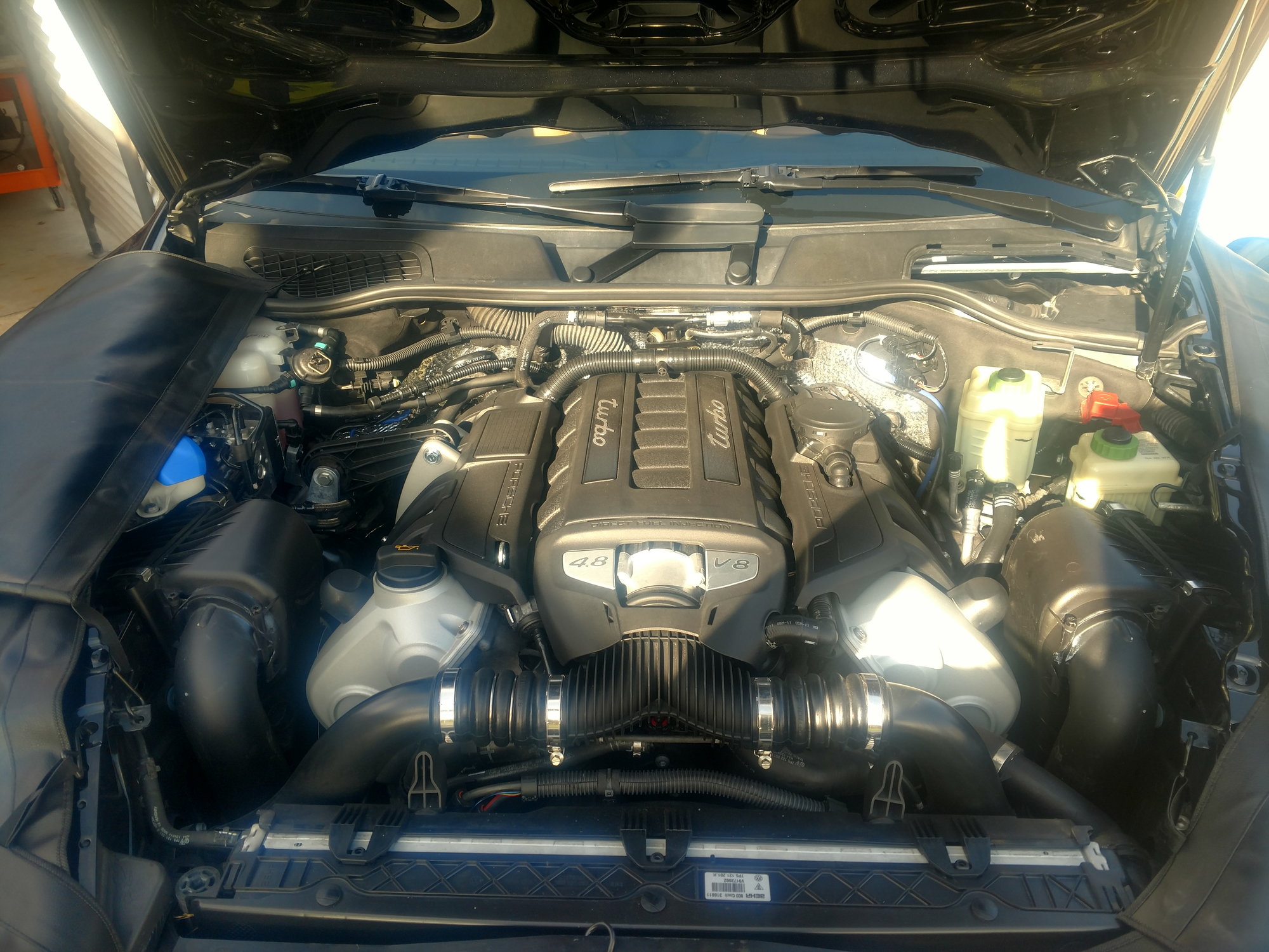
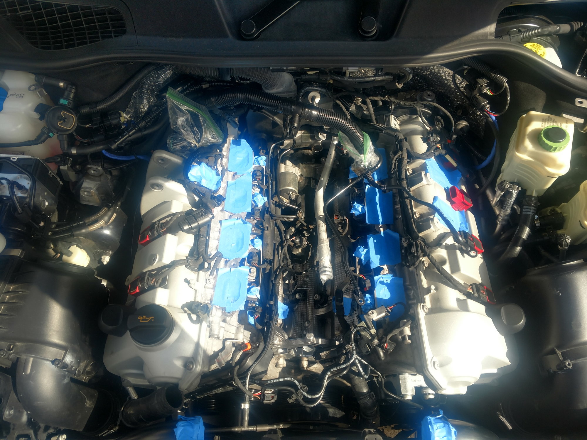
Day two. At this point when I opened the hood and saw this, I thought "I need to have my head examined...."
First thing I did was put the high-pressure fuel pump back on the same way it came off. ALLDATA mentions the fuel lines need to have a certain amount of clearance between them. Which I did.
Next, was to replace the vent hose. No need to go into details on that one. One thing I did do... I lubed all of my o-rings with Dow Molykote 55 while reassembling. I think it helps them slide easier and minimizes the chances of them getting pinched.
With the vent tube in place, the t-stat housing was next.
Again with the o-ring grease on seals, I stabbed the back of the housing with the pipe that runs across the V. Then bolted the housing to the block.
Next is the t-stat itself. I think some kind of lube is necessary for this. Even clean engine oil on the o-rings is better than nothing because it's pretty tight. Also....there is no groove or anything to line the t-stat as it goes in, so it's up to you to make sure the electrical connector is pointing up. 12:00.
And I had to lever my t-stat back into its hole. The same way I took it out. With the t-stat in place, the last piece is the water pump. As I said, the torque sequence goes around the horn. NOT in a crisscross pattern.
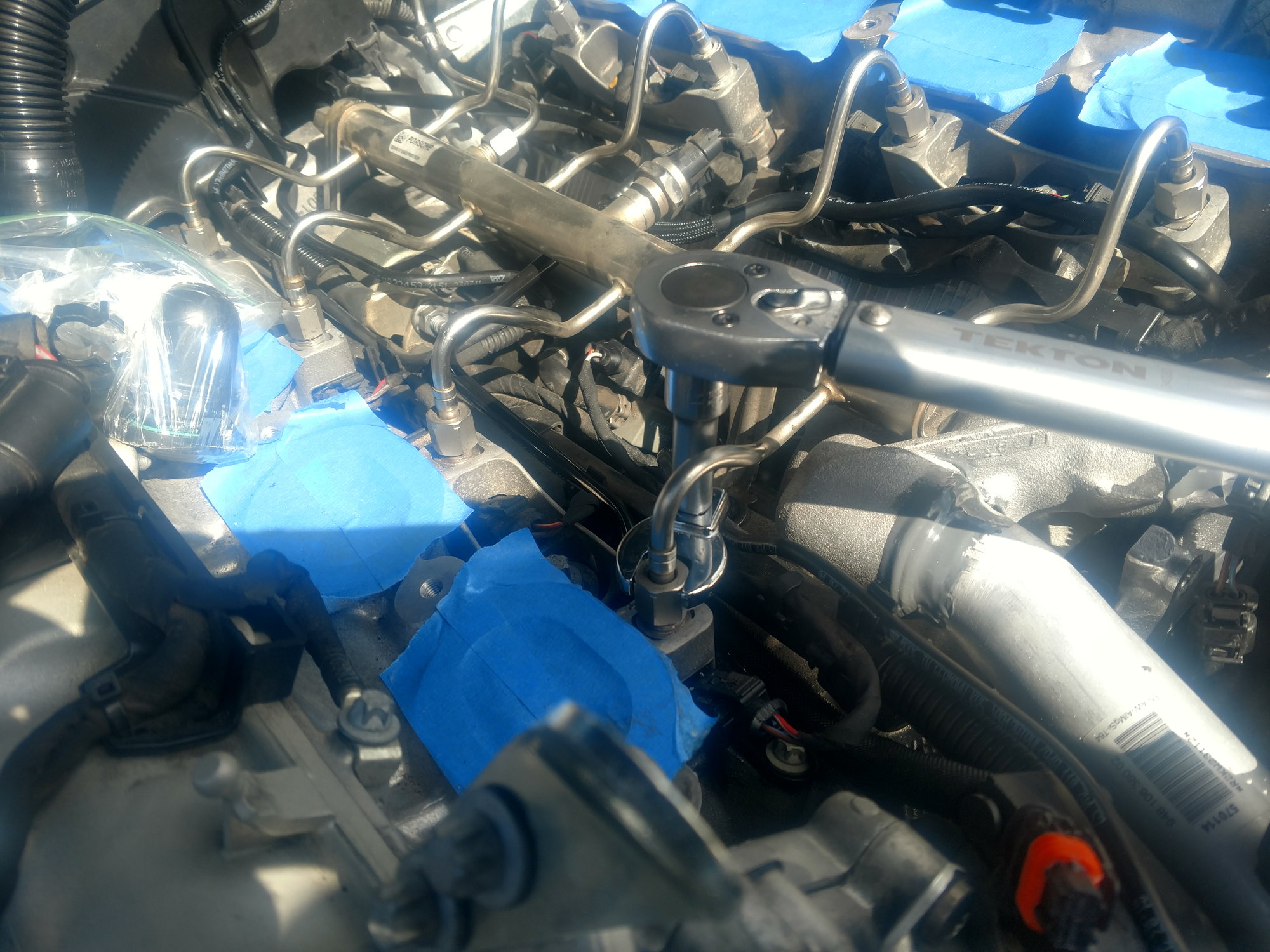
The fuel rail is next. This step took the longest for me. Once it was in place I made sure that all the injector nuts screwed in easily, by hand. I didn't want any binding of any of the fittings all the way to the fuel pump. Once I was confident nothing was in a bind is when I bolted the hold down brackets in place. Then double checked that the fittings were still not in a bind and still loose.
The next step was to tighten all the fittings. This is when I had to use the crow's foot. ALLDATA says to tighten them in two steps. TORQUE - LOOSEN - TORQUE again. This was a crucial step for me because I didn't have any way to test for fuel leaks so I had to take a leap of faith that I was leak free. This is a shot of me torquing the injectors with the crow's foot.
Everything else goes back together in the order it was removed. It's just nuts and bolts so I won't spend any time on it. And I stopped taking pictures from here on. Except for some of the tricks I used.
In order to torque the water pump pulley, I cut a section of the old serpentine belt and used a set of hog jaws to hold it to keep it from spinning while torquing the bolts. Vice grips would work the same.
Next I replaced all the pulleys and tensioner. The little caps in the center of the pulleys covering the bolts were a real pain in the *** to get off. I had to wedge a little jewelers screw driver in there to pop the caps off. once the cap came off the actual bolt was easy. I reused all my bolts. Then is just a matter of lacing the new belt through all the pulleys. I think the trick is to lace the belt through all the pulleys and leaving the loop at the tensioner. Then lever the tensioner over and slip the final loop over the tensioner.
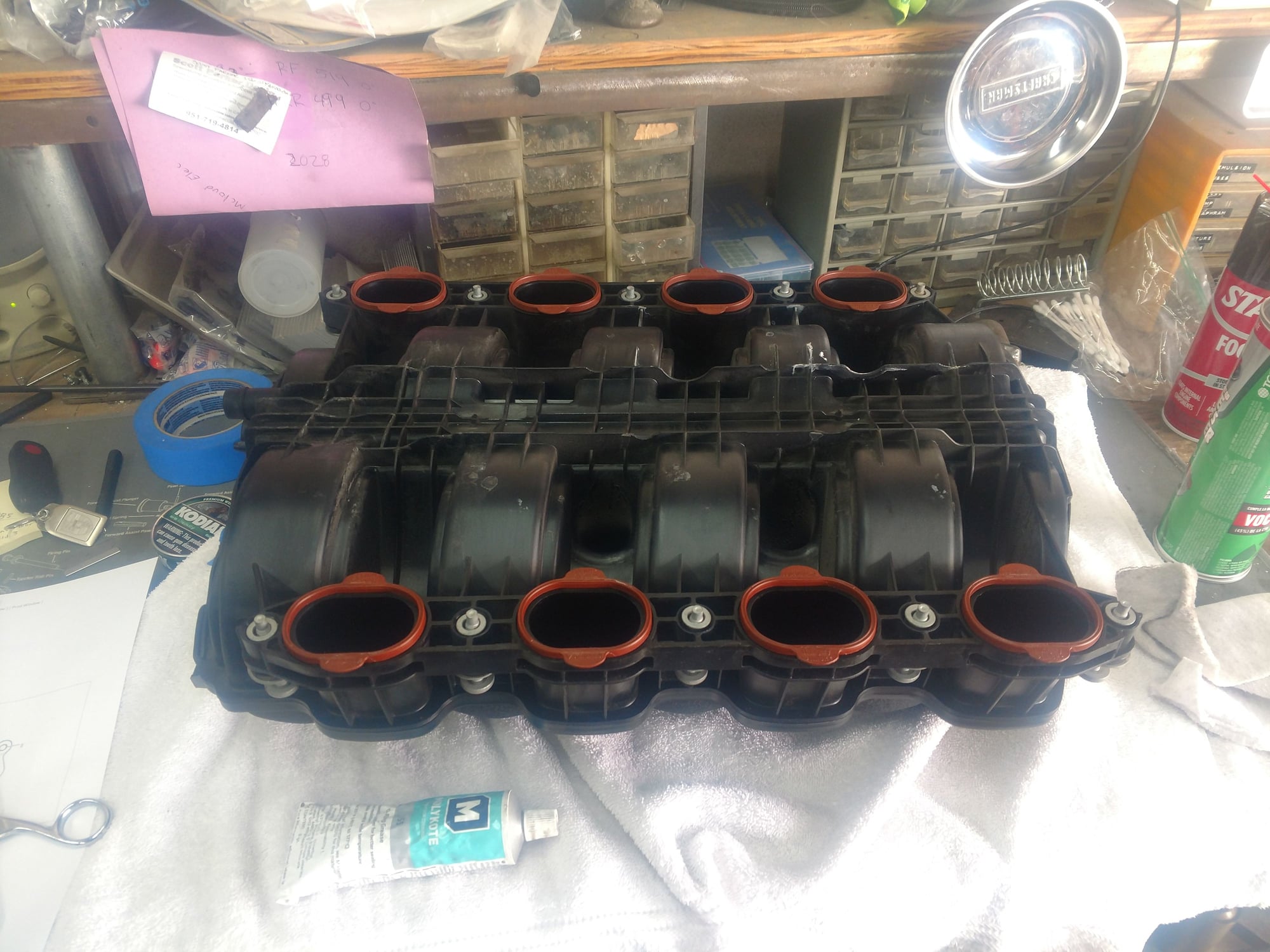
This is a shot of the manifold all cleaned up with new gaskets ready for install. I put the manifold gaskets on dry. I didn't want to take a chance of one of the gaskets falling off.
I was very careful installing the manifold. after it came to rest on the heads I double checked that all eight gaskets were still in place and hadn't dislodged.
I followed the torque sequence on ALLDATA. The only thing I changed was how I torqued the bolts. First I ran all the bolts down finger tight. Then I set my torque wrench to half the final torque and followed the sequence. Then went to full torque and followed the sequence. Then I hit them one more time at full torque. This might seem like overkill, but the manifold is made of plastic and I was worried about distorting it.
The rest is a cake walk.
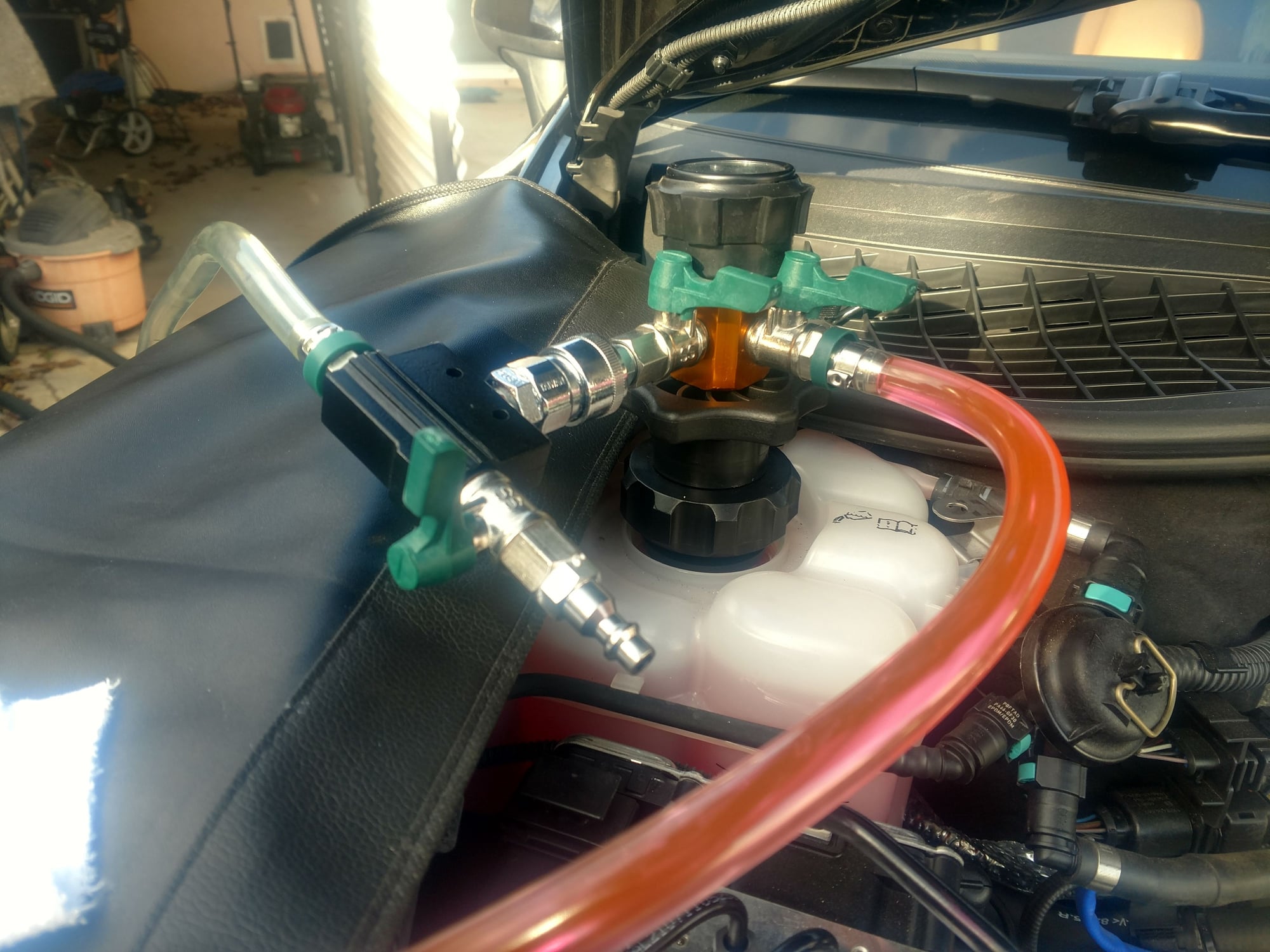
The final step was to refill the cooling system. That is where the Schwaben coolant refill kit worked beautifully. After following the directions that came with the kit, I didn't have to add an additional drop of fluid. No burping the heads, no driving like a bat out of hell down a bumpy road to work out any air bubbles. It just plain worked.
Job done.
Last edited by deilenberger; 04-20-2019 at 11:42 PM.
I wanted to give a quick update on my JB Weld repair on my coolant pipes. I had to take my intake manifold off yesterday (intake valve decarbonizing). So it was a good time to see how the repair was holding up. And it appears to just fine. I was a little concerned about the heat cycling effects on the repair but there are no signs of trouble.
Great post. I have a failed fitting that was glued into the coolant manifold. Once I got the manifold and fuel pump off, I had clear access to the fitting. The hose appeared to be in excellent shape, so I just cleaned the glue off the metal fitting and the socket with a dremel wire brush, and reassembled it with JB Weld Marine (which is the only two part product they sell that is recommended for use with Aluminum, as their other products have steel in them).
Rather than drill and tap a screw into the fitting to prevent separation in the future (which another person on the forum did), I drilled a 1/8" hole and glued an aluminum aircraft compression rivet in the hole. This way there is no dissimilar metal issue. If you do prefer a screw, get an aluminum one from McMaster.
Day two. At this point when I opened the hood and saw this, I thought "I need to have my head examined...."
First thing I did was put the high-pressure fuel pump back on the same way it came off. ALLDATA mentions the fuel lines need to have a certain amount of clearance between them. Which I did.
Next, was to replace the vent hose. No need to go into details on that one. One thing I did do... I lubed all of my o-rings with Dow Molykote 55 while reassembling. I think it helps them slide easier and minimizes the chances of them getting pinched.
With the vent tube in place, the t-stat housing was next.
Again with the o-ring grease on seals, I stabbed the back of the housing with the pipe that runs across the V. Then bolted the housing to the block.
Next is the t-stat itself. I think some kind of lube is necessary for this. Even clean engine oil on the o-rings is better than nothing because it's pretty tight. Also....there is no groove or anything to line the t-stat as it goes in, so it's up to you to make sure the electrical connector is pointing up. 12:00.
And I had to lever my t-stat back into its hole. The same way I took it out. With the t-stat in place, the last piece is the water pump. As I said, the torque sequence goes around the horn. NOT in a crisscross pattern.
The fuel rail is next. This step took the longest for me. Once it was in place I made sure that all the injector nuts screwed in easily, by hand. I didn't want any binding of any of the fittings all the way to the fuel pump. Once I was confident nothing was in a bind is when I bolted the hold down brackets in place. Then double checked that the fittings were still not in a bind and still loose.
The next step was to tighten all the fittings. This is when I had to use the crow's foot. ALLDATA says to tighten them in two steps. TORQUE - LOOSEN - TORQUE again. This was a crucial step for me because I didn't have any way to test for fuel leaks so I had to take a leap of faith that I was leak free. This is a shot of me torquing the injectors with the crow's foot.
Everything else goes back together in the order it was removed. It's just nuts and bolts so I won't spend any time on it. And I stopped taking pictures from here on. Except for some of the tricks I used.
In order to torque the water pump pulley, I cut a section of the old serpentine belt and used a set of hog jaws to hold it to keep it from spinning while torquing the bolts. Vice grips would work the same.
Next I replaced all the pulleys and tensioner. The little caps in the center of the pulleys covering the bolts were a real pain in the *** to get off. I had to wedge a little jewelers screw driver in there to pop the caps off. once the cap came off the actual bolt was easy. I reused all my bolts. Then is just a matter of lacing the new belt through all the pulleys. I think the trick is to lace the belt through all the pulleys and leaving the loop at the tensioner. Then lever the tensioner over and slip the final loop over the tensioner.
This is a shot of the manifold all cleaned up with new gaskets ready for install. I put the manifold gaskets on dry. I didn't want to take a chance of one of the gaskets falling off.
I was very careful installing the manifold. after it came to rest on the heads I double checked that all eight gaskets were still in place and hadn't dislodged.
I followed the torque sequence on ALLDATA. The only thing I changed was how I torqued the bolts. First I ran all the bolts down finger tight. Then I set my torque wrench to half the final torque and followed the sequence. Then went to full torque and followed the sequence. Then I hit them one more time at full torque. This might seem like overkill, but the manifold is made of plastic and I was worried about distorting it.
The rest is a cake walk.
The final step was to refill the cooling system. That is where the Schwaben coolant refill kit worked beautifully. After following the directions that came with the kit, I didn't have to add an additional drop of fluid. No burping the heads, no driving like a bat out of hell down a bumpy road to work out any air bubbles. It just plain worked.
Job done.
THANK YOU so much for taking the time to document and share the process. I learned a lot!
 04-09-2019, 11:06 PM