When you click on links to various merchants on this site and make a purchase, this can result in this site earning a commission. Affiliate programs and affiliations include, but are not limited to, the eBay Partner Network.
Grade 12.9 is absolutely stronger than Ti. Generally speaking, the torque specs for any given bolt is answering the question, "How much force can I safely apply to this bolt without it failing?" Of course, the material you are clamping inside the bolt must also be able to handle that load (hence washers bend when you torque a bolt too much). The torque spec is just a value that can be reverse calculated to find what that tensile force is. If you look at the Force row from the calcs above, you see that a titanium bolt torqued to ~144 ft-lbs. can safely (85% of yield strength) handle ~15,750 lbs of force. Another way of saying this is, "This bolt will clamp other things inside of it to 15,750 lbf without the bolt failing." Now, if you think about it, the stainless steel stud you were looking at (~69 ft-lbs, ~7500lbf) can still clamp with the equivalence of 3.75 tons of force. The unknown question is, "do the dynamics of the braking system exceed this 7500lbf?" That answer, unfortunately, I do not have. Then again, the Gr 12.9 bolts can clamp "only" about three times more than the stainless studs (~21775 lbf from the calcs above). Was that just a safety call from the designers? Maybe. It could be that they ran simulations of cornering and braking at some specific speed and the calipers apply 10000 pounds of force at the bolts and they chose a safety factor of 2:1. It could just be that they had a surplus of 12.9's and decided to run with them. I honestly don't know.
You should also consider the material that you are bolting into. Remember even if you use studs, those studs will be threaded into your custom adapter plate. Any force that you put on the nut end will transfer through the stud to the adapter plate; the same as if you were bolting directly into the adapter plate. Also, if you do go with custom studs, make sure they put a flat area (tell them to add "Flats") in between the left end and right end threads so you can take a wrench and torque the studs into the adapter plate. Make sure that the cross sectional area of the bolt at the flats is close to or equal to the threaded portions' cross sectional area.
I'm sorry if all of this comes off as fear mongering. I'm not trying to scare you into one bolt or the other; just want you to have the data and facts before you start torquing down bolts into what I imagine are expensive custom adapters.
No fear mongering viewpoint from my end and I absolutely appreciate the information you've provided. Because of it, I've decided not to use the stainless 304 hardware and will most likely go with the Ti flange bolt. The adapter is made of steel and is similar to the same type of adapter Porsche uses with the current brake setup, but that they only sell as part of the caliper assembly - in fact, the dimensions of the one I'm having made actually look more robust than the on the car today, as will the bolts going through the caliper into the adapter since I'll be using M14s and they look to be M12s. This is the current caliper setup.
Maybe moving from the current 380mm rotor to the PCCB 410 mm rotor generates enough additional angular force that the hardware needs to be upsized or maybe the coefficient of friction on the PCCB brakes can exceed that which can be applied by the steel counterparts, or who knows what else, but after looking at the material stretch specs for Stainless, Ti, & Grade 12.9, I don't feel very comfortable using anything less than the Ti. I have started communication with a Ti specialty vendor about making some proper bolts and will share the name of them if we can put the deal together. I am also looking at safety wiring the tops of the 2 bolts together so that if there is any tendency for them to loosen, they won't be able to or I'll be able to see evidence of it in the wire.
Petza, how difficult is it to instal the drive shaft? Hoping to tackle it myself.
I am 4 weeks in waiting to get mine, hopefully arriving any day now. Getting excited.
Do you need to drop the exhaust? I read something about special tool to center the drive shaft. Did you use one?
Any input would be great. Thank you.
Sorry, but I actually can't answer that. When I was having the dealer drain and refresh the old fuel and go through the car, I just had them install it while they were under there. I'm assuming if there was a special tool needed that they used it as I don't have any issues with the driveshaft. When ordering yours, did you take some measurements for the location of the center bearing support bracket so you could instruct the driveshaftshop to not locate any balance weights in that area? If they locate them there, you may run into the same thing I did where you have to adjust the cradle to create the proper clearance and that will make the install more involved.
Sorry, but I actually can't answer that. When I was having the dealer drain and refresh the old fuel and go through the car, I just had them install it while they were under there. I'm assuming if there was a special tool needed that they used it as I don't have any issues with the driveshaft. When ordering yours, did you take some measurements for the location of the center bearing support bracket so you could instruct the driveshaftshop to not locate any balance weights in that area? If they locate them there, you may run into the same thing I did where you have to adjust the cradle to create the proper clearance and that will make the install more involved.
Thank you for the reply. Based on the info online, many replaced the drive shaft without the tool. Fingers crossed.
As far as balance weights, I ordered CF version, which is slimmer than Aluminum one, it should be fine.
Thank you for the reply. Based on the info online, many replaced the drive shaft without the tool. Fingers crossed.
As far as balance weights, I ordered CF version, which is slimmer than Aluminum one, it should be fine.
Good deal. Interested to hear your impressions of the CF one once you have it installed.
Thank you for the reply. Based on the info online, many replaced the drive shaft without the tool. Fingers crossed.
As far as balance weights, I ordered CF version, which is slimmer than Aluminum one, it should be fine.
The centering tool becomes obsolete when you switch to a one piece. Balance weights will be located where they be located, period. The balance machine tells the operator where to place the weight. Short of making a whole new driveshaft with new balance characteristics nobody has a choice where they go except the balance machine. It's written in stone. A touch of grinding on a part of the unibody that will never be used again after the switch and has no structural contribution is of no consequence.
Balance weights will be located where they be located, period. The balance machine tells the operator where to place the weight. Short of making a whole new driveshaft with new balance characteristics nobody has a choice where they go except the balance machine. It's written in stone.
I think it's possible that if you knew where you didn't want to put weights, when you initially tried to balance the driveshaft, if the machine said the weights needed to be placed in that area, it might be possible to add a little weight somewhere else (out of that area), then try to rebalance it, and since the dynamics had changed a little because of the additional weight, the calculated position of the next set of weights could also be changed until you found a combination where the driveshaft was balanced but all weights were outside the restricted area.
Sounds like for Rossi none of this will matter since he went with the CF version, which is thinner, and it won't have a restricted area. As a general rule, I don't usually like to make modifications to a vehicle that aren't really reversible, so wanted to avoid doing any grinding or cutting on the OEM bearing support to create the necessary clearance for the driveshaft weights, just in case I needed to revert back to the OEM driveshaft configuration at some point.
Looking at what you ground its completely negligible IMO. But I'm all about the thinking ahead. I think you are right about tricking the balance machine but that's really funky and most specialty shops aren't into that kind of thing.
Just received confirmation from my contact in Germany that the custom PCCB front caliper adapters are also completed. I expect to receive them by Thanksgiving and will be taking them to the powder coater to have them done to match the yellow PCCB calipers.
I'll be installing them with these gorgeous Titanium fasteners that I had custom done by Ti64 (http://www.ti64.com/default.asp). I also had them drill the tops so I could safety wire the mounting bolts together to prevent any chance of them loosening.
And at the same time, will be installing these braided stainless brake lines from ECS Tuning.
and doing a complete bleed with Motul RBF600, which I run in all my cars.
Looking good! Did the bolt co. provide torque specs for them?
Yes, they did. Properly tensioning a fastener has to do with creating the proper amount of stretch for the material it's made from more than an absolute number. The Grade 12 OEM caliper bolts require 200 ft. lbs to be properly tensioned. These Ti bolts should have the threads lubricated with Ti-Treat Moly Paste and then be torqued to 90-100 ft. lbs, and that will generate less than 1mm of bolt stretch but will have them properly tensioned. Because the torque value will be lower and they're a critical safety component on the car, I had them drill them for safety wire to provide that extra bit of peace of mind that even if for some reason they were to loosen, they won't be able to come completely out. Since I seem to be exploring new ground with retro fitting 958 calipers to the 957, it seems like erring on the side of caution is the right way to go, since my family is usually in this car with me when it's being driven. The PCCBs should have extremely long life out of both the pads and rotors, and this vehicle will only see about 5,000 miles of use per year, so the little bit of extra time spent wiring the bolts should not have to be redone for a decade.
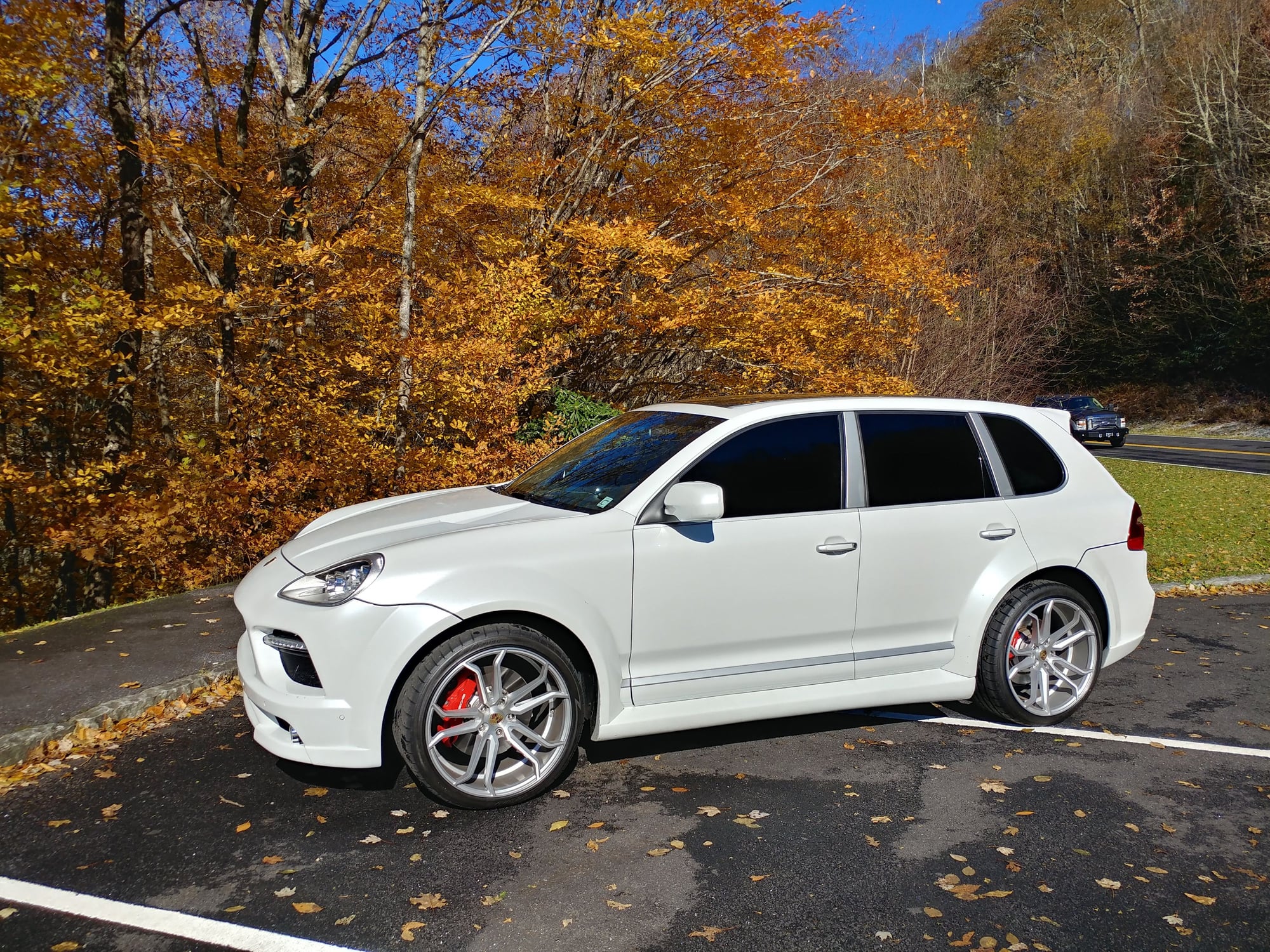
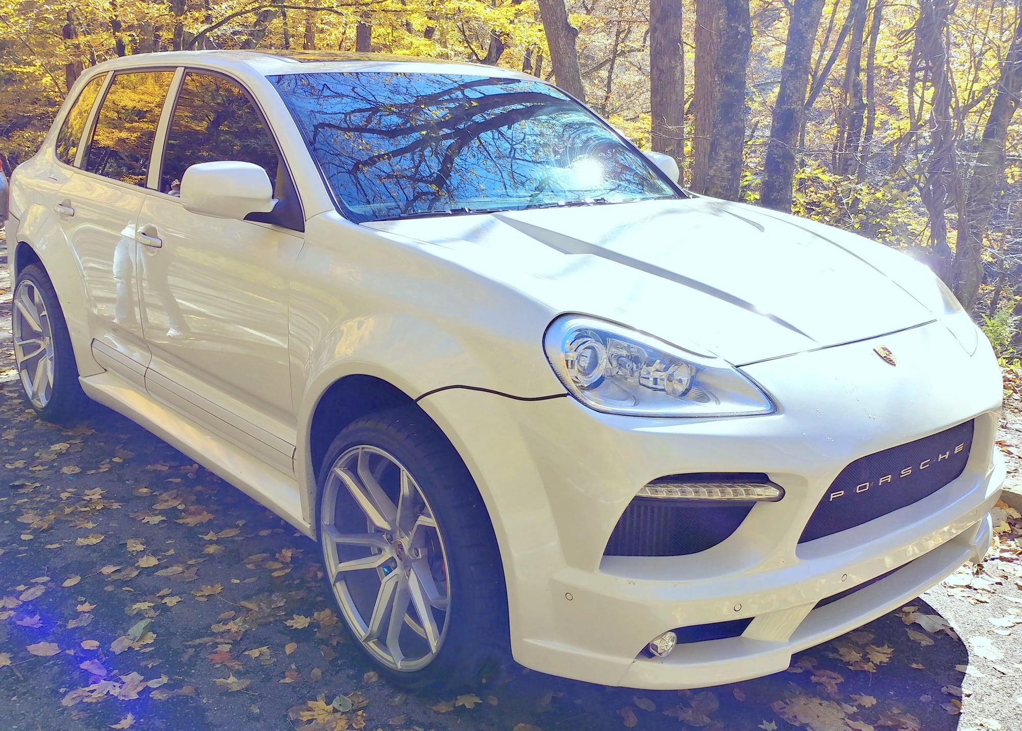
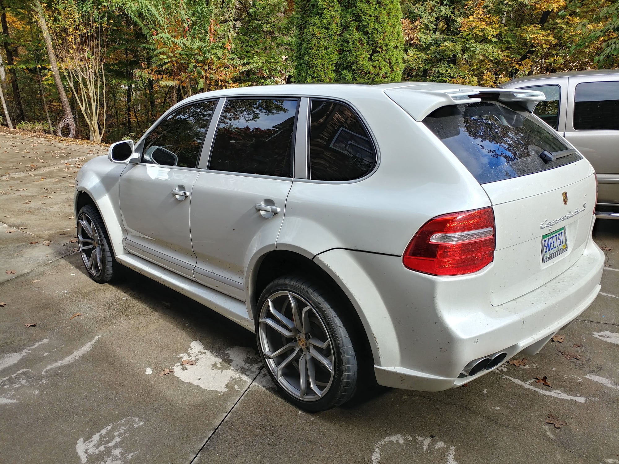
I can't believe how much junk the front brakes on this car generate though - don't know if it has something to do with the wheel design and airflow through it or the bodywork but the amount of black filth stuck inside the wheels after every trip is remarkable, especially if it happens to rain while we're gone, like this past weekend. I can't wait to get the PCCBs installed to make wheel maintenance so much easier.
I'm not sure how far you can zoom in on the photo, but check out the debris all down the sides from the wet mountain pass and the inside of the front wheels.
Don't worry though, I washed it as soon as we got home and tucked her back away all clean and shiny.
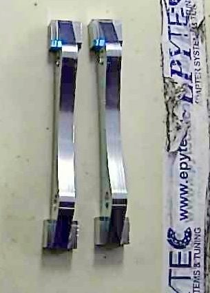
The PCCB Caliper adatpers from Epytec in Germany arrived today.
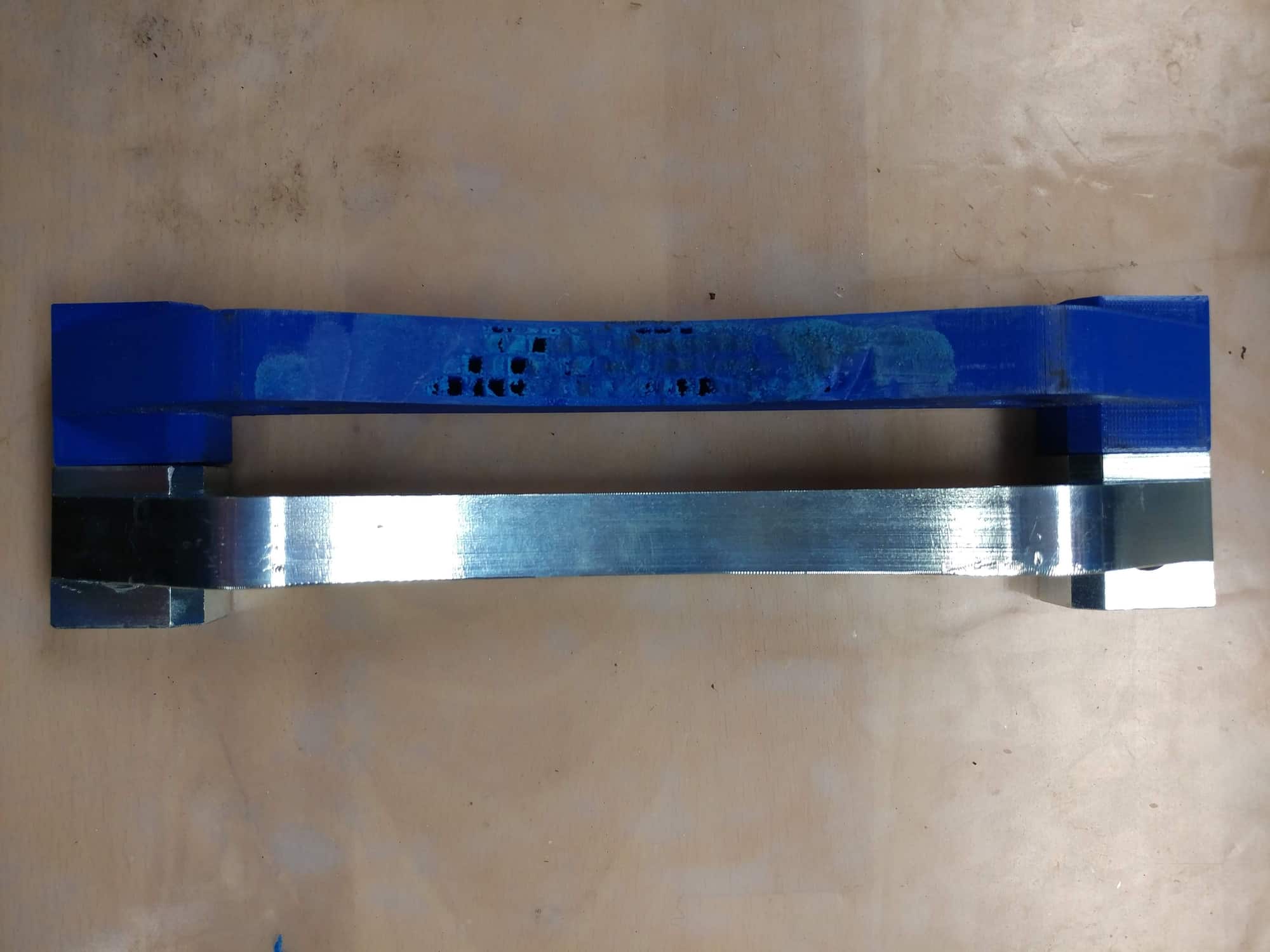
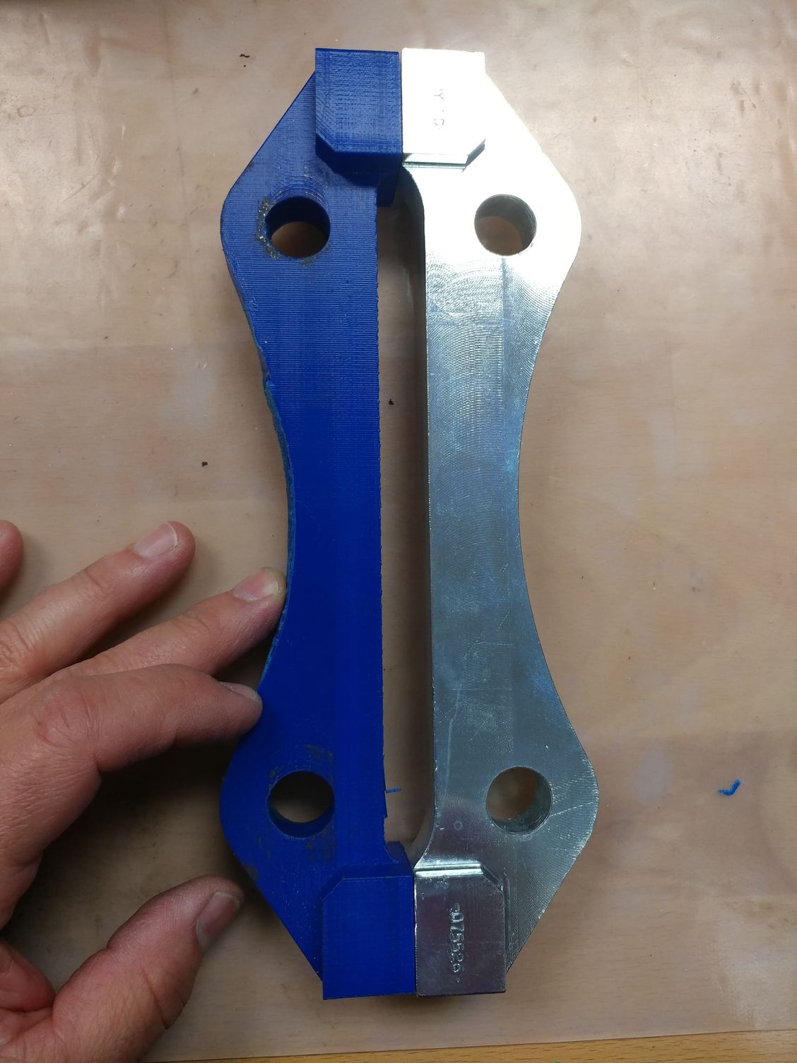
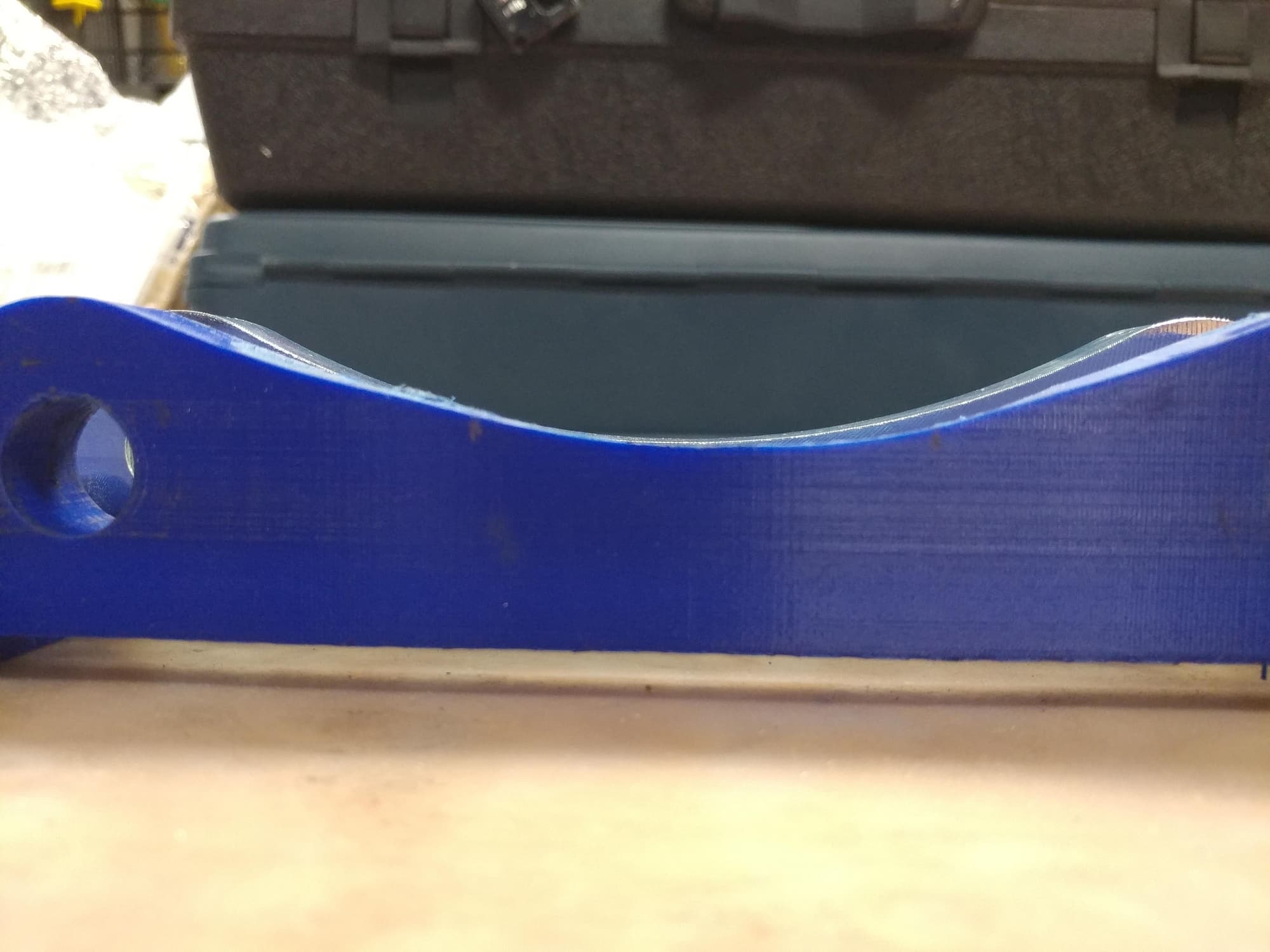
First thing I did upon opening them was compare them to the 3D printed sample I was sent for a test fit a few weeks ago. Comparing the metal versions to the plastic one, it looks like we're in good shape.
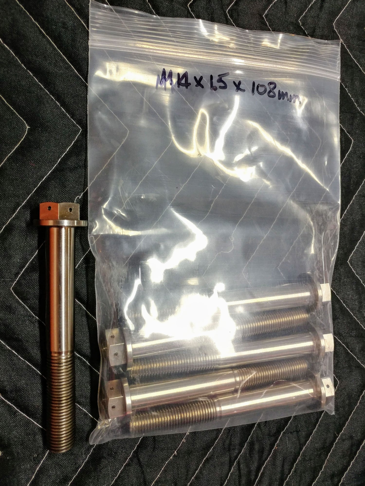
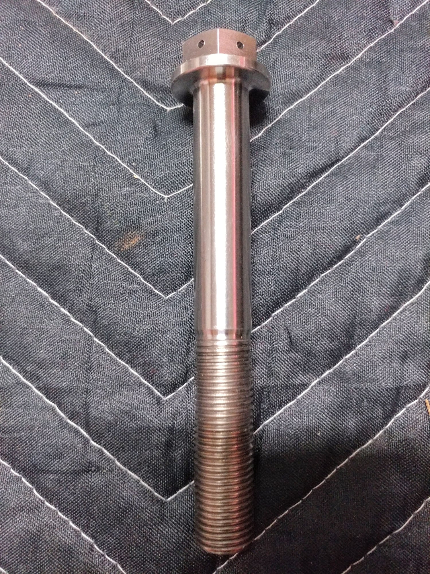
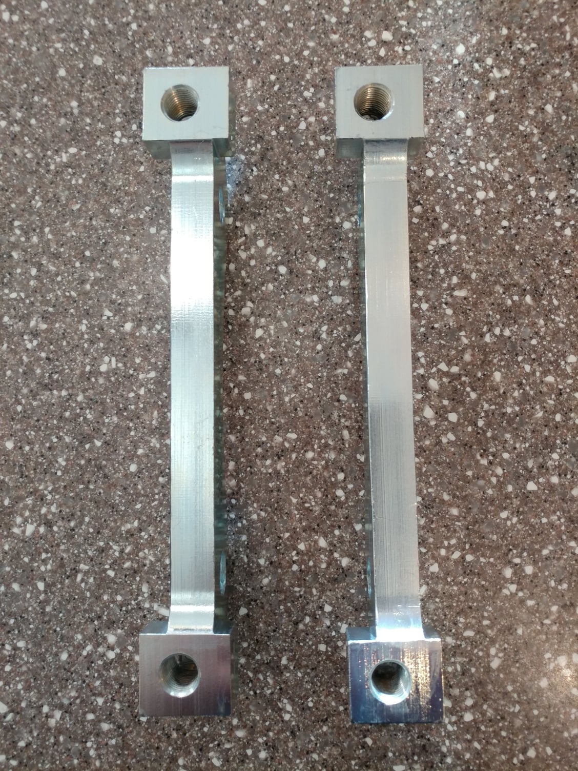
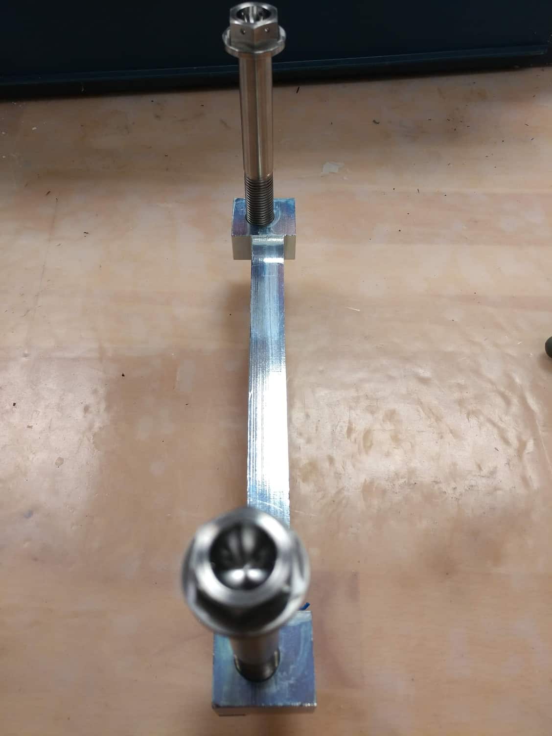
Next, I took the Titanium mounting bolts I sourced from Ti-64 and hand threaded one into the caliper adapter. Thread diameter and pitch are correct - we're off to a good start.
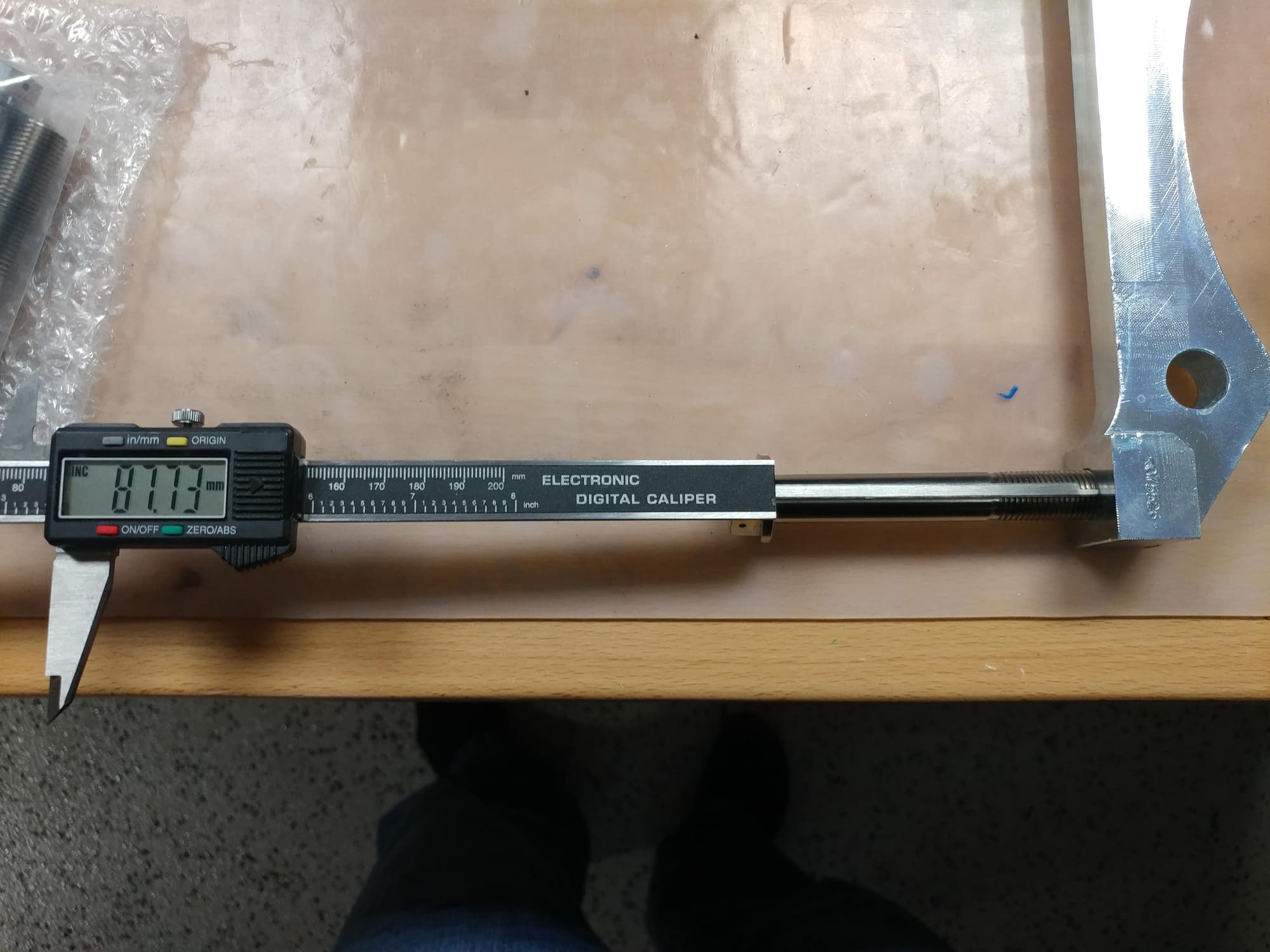
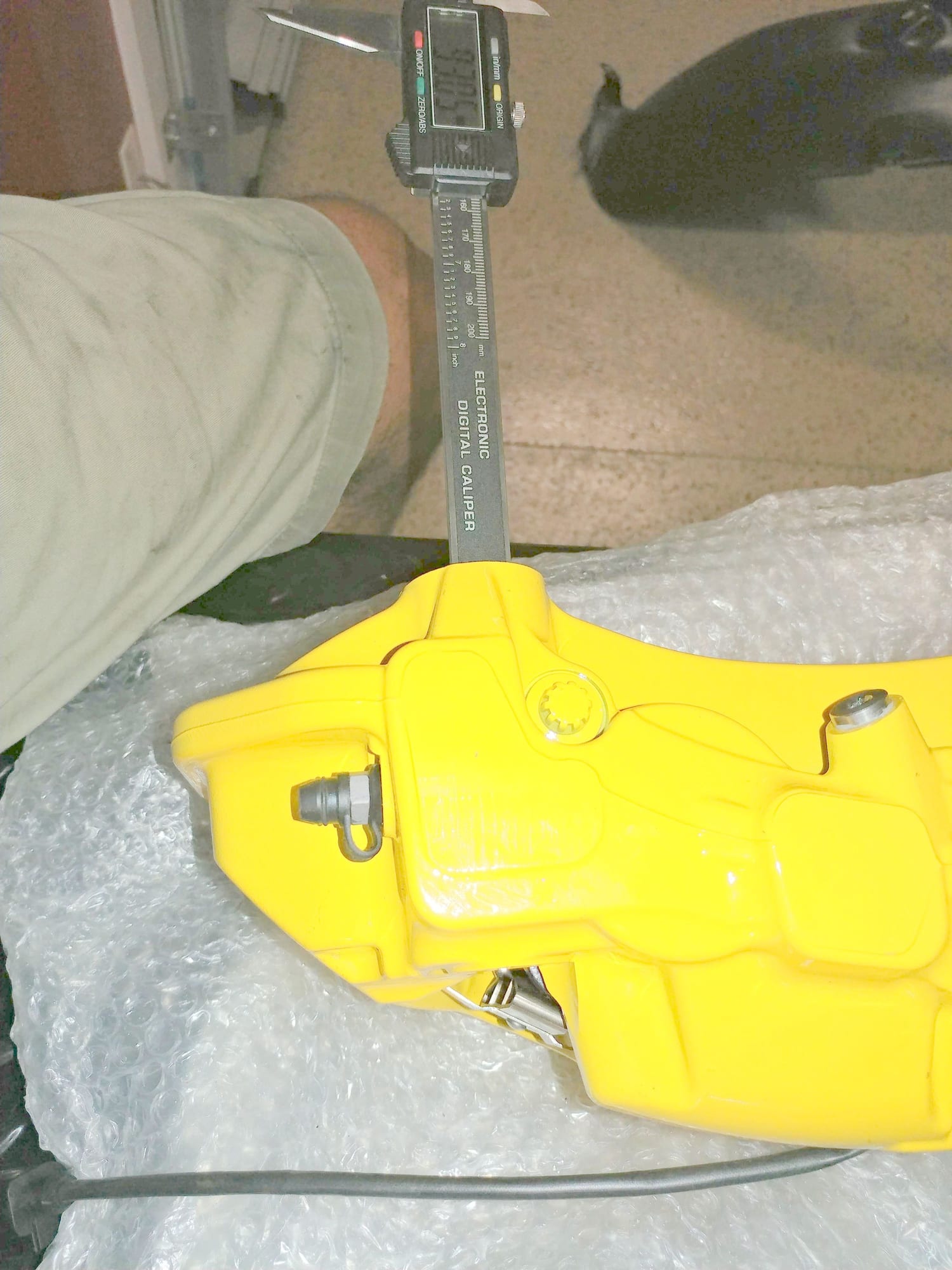
Next, I continued threading in the Ti bolts until they lightly bottomed out, then measured the exposed shank length from under the bolt head to the caliper adapter. The purpose of this was to compare this length to the dimension through the caliper. What I want is for the exposed shank length to be shorter than the distance through the caliper so I could properly torque the bolts without the mounting bolts bottoming out in the adapter before reaching the proper torque. More good news - exposed shank length was 87.73 mm and the distance through the caliper is 93.05 mm, which means after torquing the bolts which will make them stretch 1-1.5 mm, I'll end up with about 4mm of space at the end of the bolt (93.05 - 87.73 - 1 = 4.32 mm). The thickness of the adapter where the bolt threads in is 21.76 mm so I'll end up with 17.46 mm of thread engagement into the adapter (21.76 - 4.3 = 17.46) which should be plenty. OK, progressing nicely.
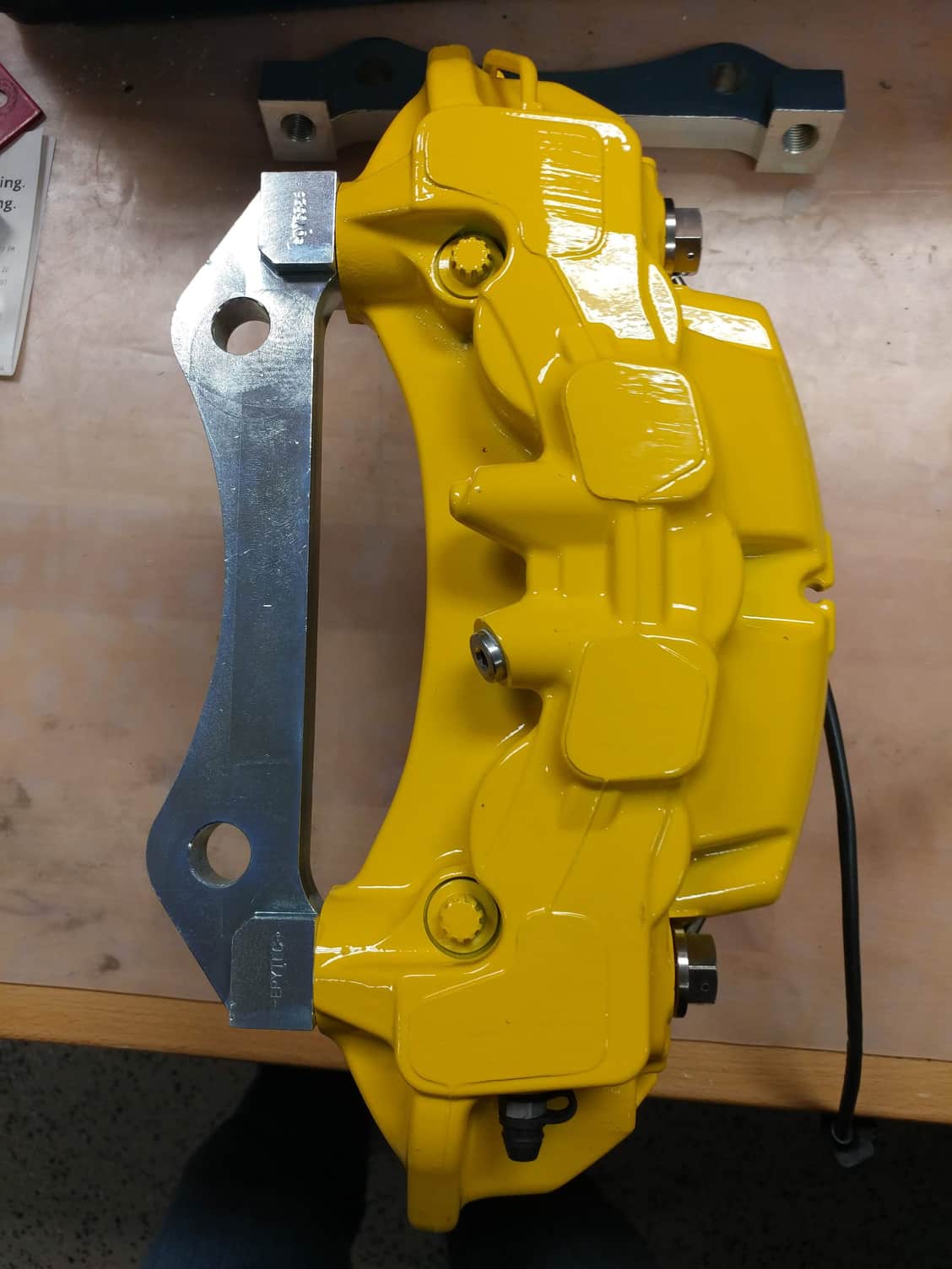
Next, I measured the thickness of the adapter at the curve. For those of you following along, you'll remember that the 3D printed sample at 27mm was too thick in this area and contacted a flange on the wheel carrier. One nice thing about receiving the 3D printed sample before production of the metal ones is that it allowed me to easily rework the plastic model and send adjusted dimensions back to Epytec to be used for the final adapters. Reworking the plastic adapter on the bench sander I had determined that in this area, I needed a width of 24mm to clear the flange. I sent them a new spec of 23mm to have 1mm of margin and asked that they modify the curve using this dimension at the center point, which they did, so should be all set there. So far so good.
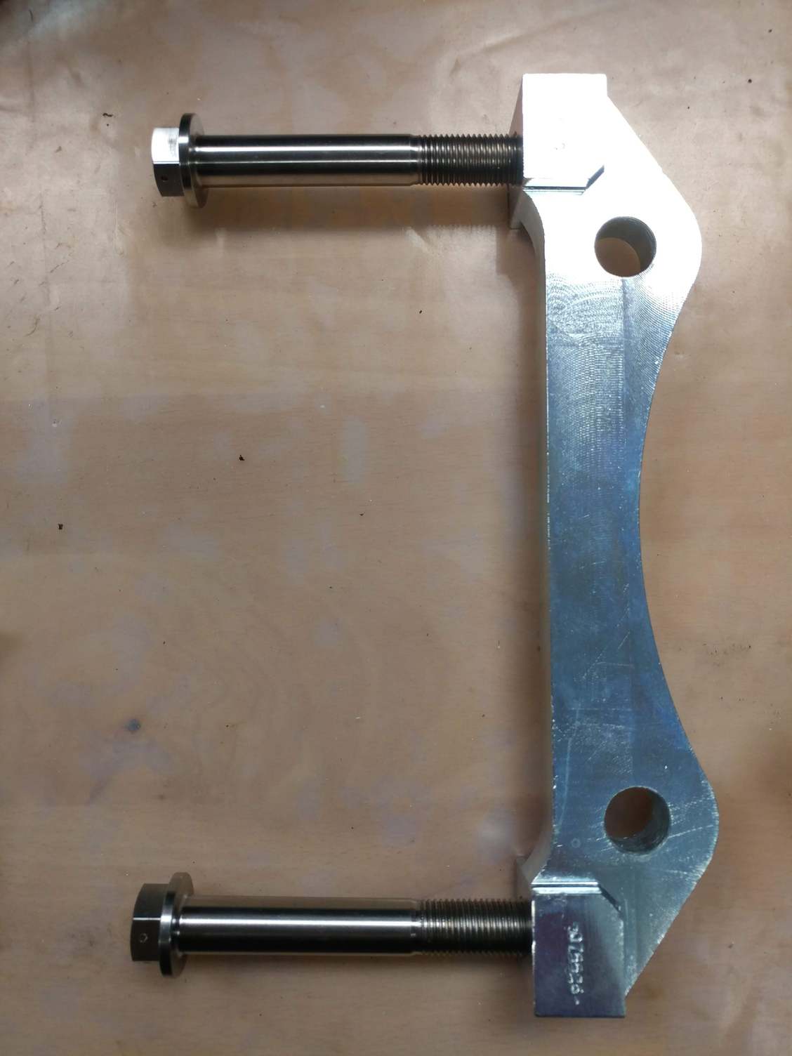
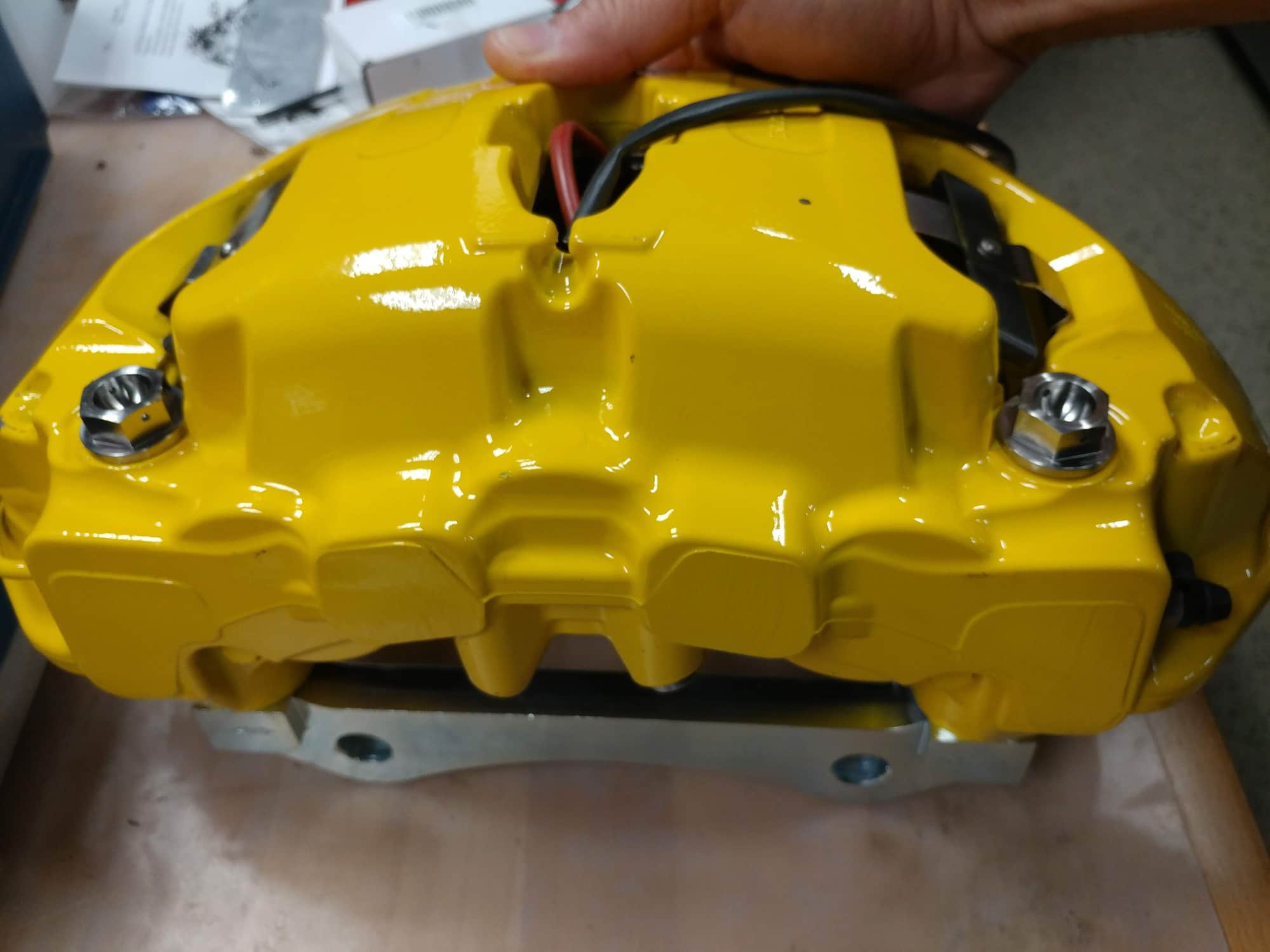
Now for the real moment of truth. There is zero wiggle room when the Ti mounting bolts are passed through the caliper mounting holes as you don't want the caliper shifting around on the bolts when braking forces are applied. This means my center-to-center dimension measurements of the calipers have to be perfect for the bolts to thread into the adapter. Holding my breath, I inserted 2 of the mounting bolts and by hand started the thread engagement into the adapter. Working each bolt a few turns at a time by hand, I drew the two pieces together, and to my jubilation, they came together perfectly with the mounting post surfaces of the caliper mating to the adapter surfaces perfectly square. Huge sigh of relief.
So, after verifying that everything appears to be good to go for the install, I took the adapters off to the powdercoater wtih one of the pieces I had cut from the original mounting post when shortening them, so they could match the color to the PCCB yellow. I should get them back either late next week or the week after, which is fine, as I likely won't get to the actual 4-corner installation until I'm off on vacation for the Christmas Holiday.
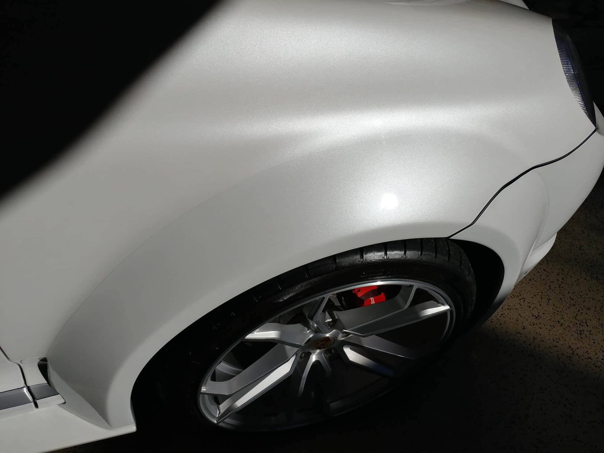
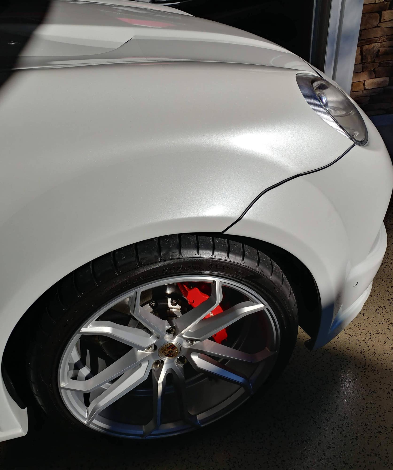
Opened the garage today and the sun was coming in just right to really highlight the pearl effect of the paint, so I snapped a couple pics The lines you can see is the clearbra to protect it from road rash.


 09-24-2018, 12:46 AM


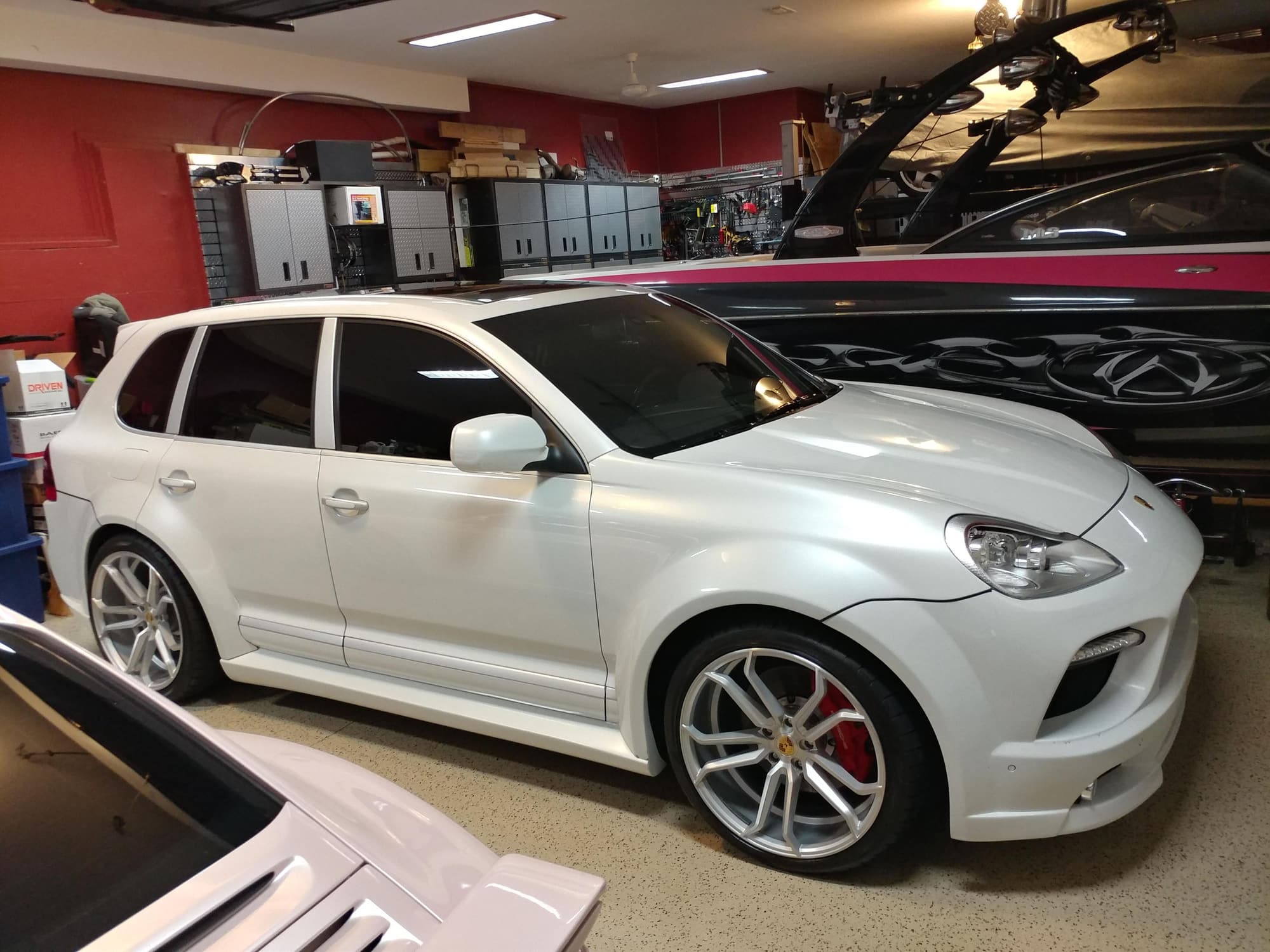


 The lines you can see is the clearbra to protect it from road rash.