When you click on links to various merchants on this site and make a purchase, this can result in this site earning a commission. Affiliate programs and affiliations include, but are not limited to, the eBay Partner Network.
There are a number of us that have been unhappy with the reversing lights on their steeds and I, like many others have tried lots of different LEDs in an attempt to get some more light output. Unfortunately the pesky canbus tries to block any changes so I have now decided on a different approach.
This might not be to everyone's taste as it requires a bit of permanent modification and is irreversible once completed, but I am really chuffed with the result.
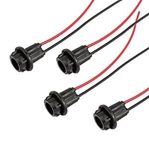
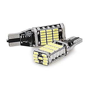
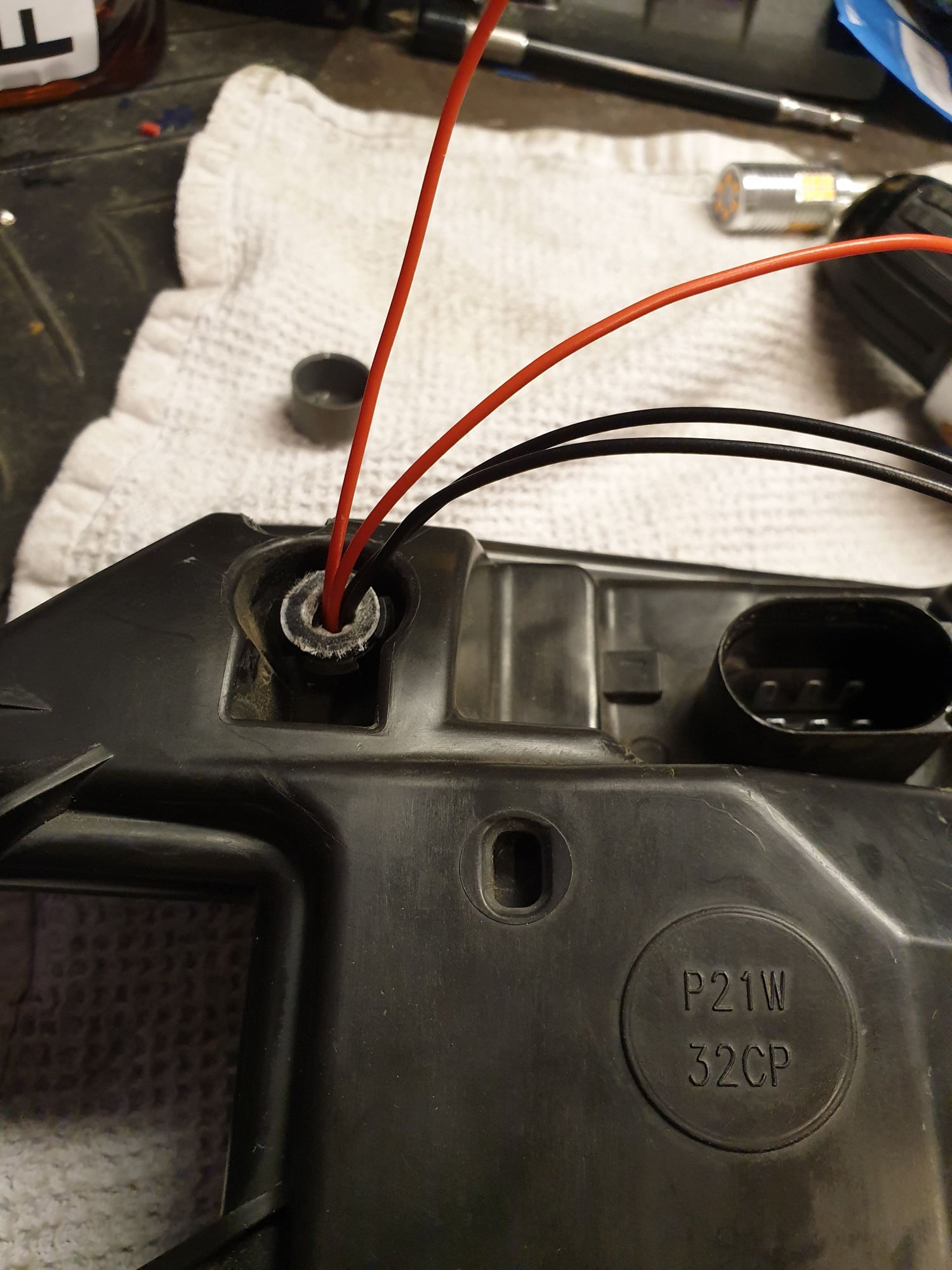
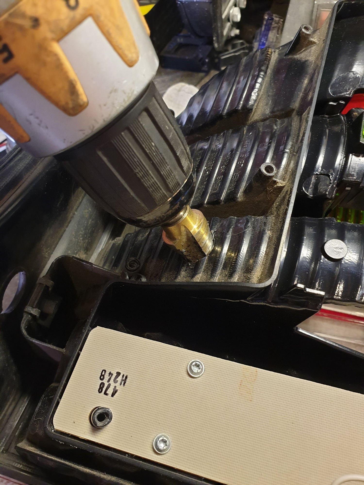
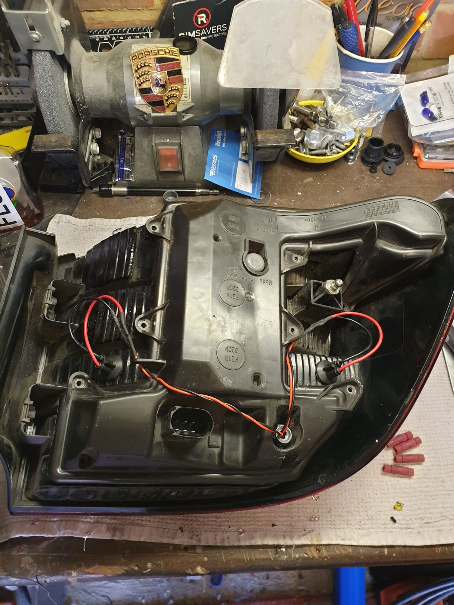
I started with buying some rubber T10 bulb holders and some super bright LEDs
Not being other than an electric hack myself, when you draw power from the bus bar which powers the original backup light, why doesn�t the new power wires draw even more power and then create error warnings? How do the bus bars isolate this? Do you still use the standard required incandescent bulb to prevent the error? How the h does this work?
Cheers from Kinsale
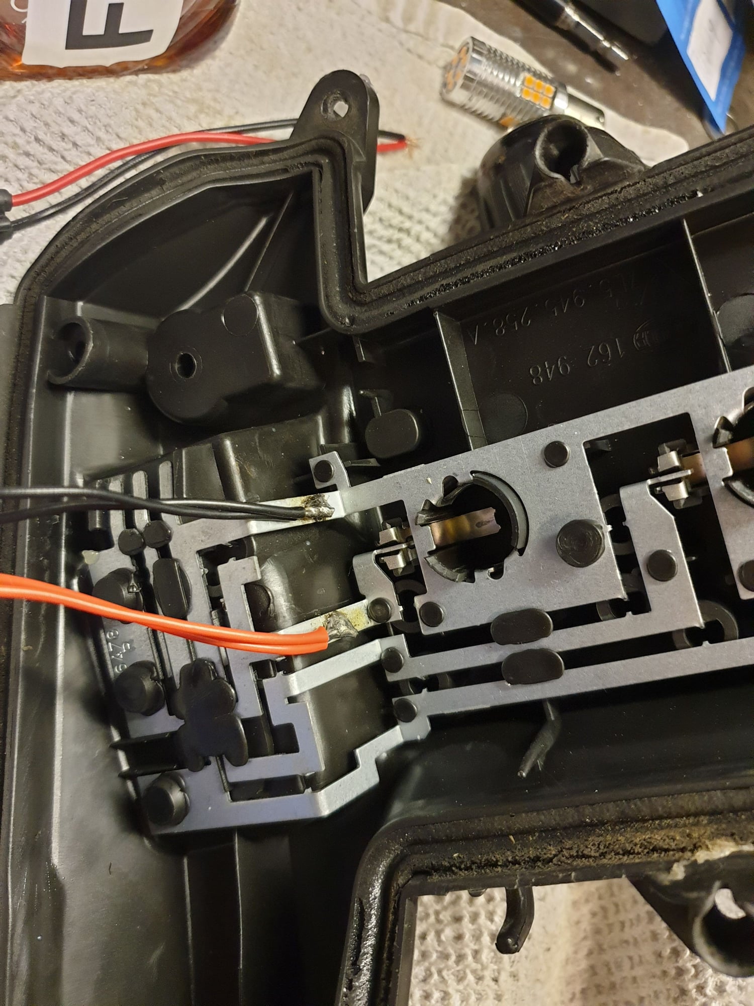
The standard current draw with a 21w bulb is in theory (rounding up) around 2 Amps. The canbus likes this value very much and gets quite upset if it sees anything different - he then starts having hissy fits and swears at everybody. The LED replacement bulb draws a lot less than 2 Amps ........ unless there are THREE of the little blighters - this makes the canbus very happy again and all is well in dashboard land.
So to summarise, there are no changes in current draw, no need to change fuse values, nada - just a LOT of extra light. I reckon about 3000 lumens for each light unit if the manufacturer's claims are correct.
Just returned home tonight and reversed into my usual spot and GOD THESE THINGS ARE BRIGHT! 🙃
Just a clarification - one of the three LED's was installed in place of the original incandescent bulb? Giving you 3X the current draw of a single LED, close enough to the incandescent..?
Think there will be any issue with heating? I realize normally the reverse light won't be left on for long, and LEDs put out much less heat than the incandescent - but still - there may be some considerable heat from them, and if they're located close to the outer clear lens there might be an issue - or not. The two going into the old socket appear to have some heat-sinking on the base, but the T10 ones appear not to have any.
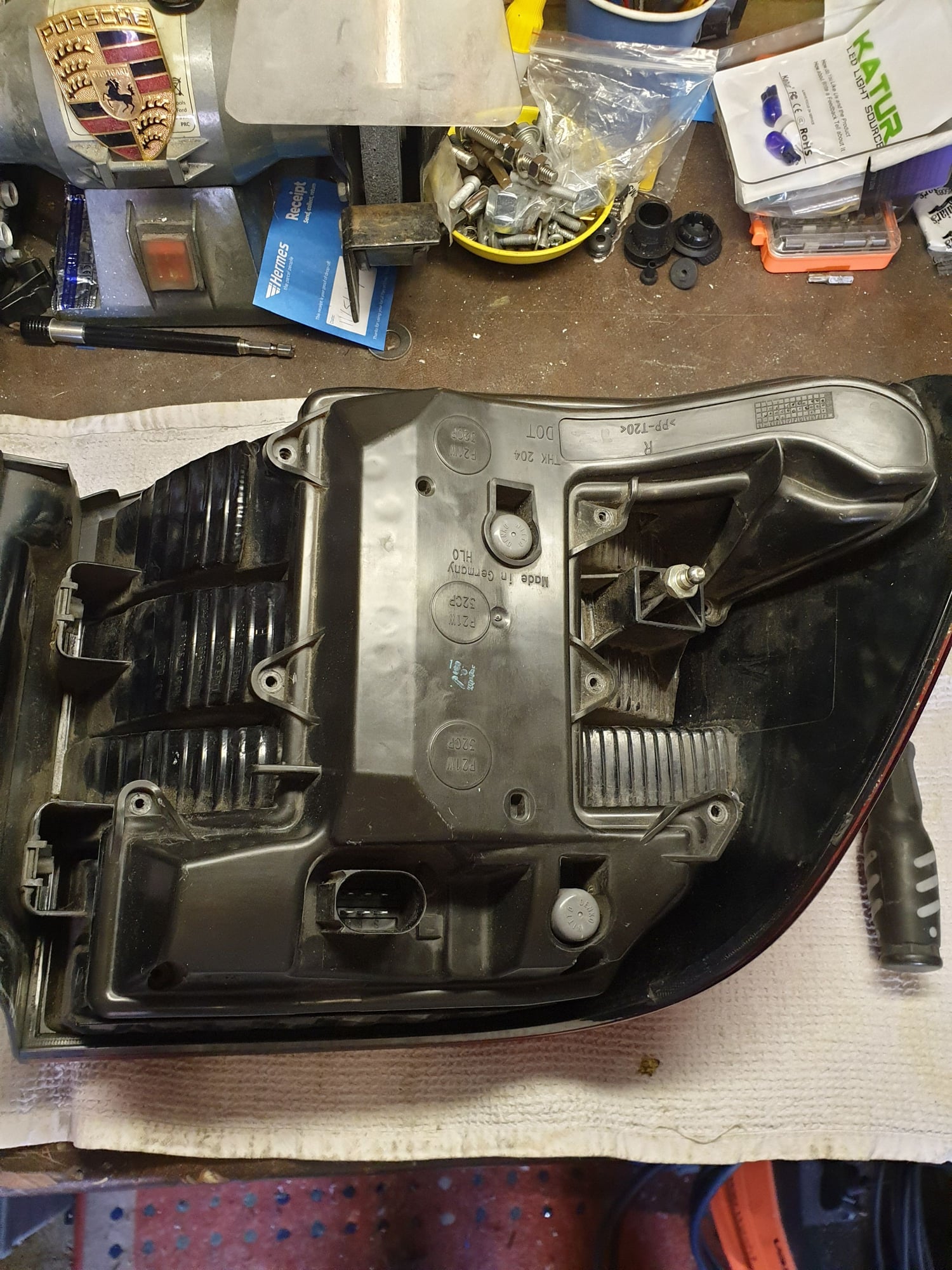
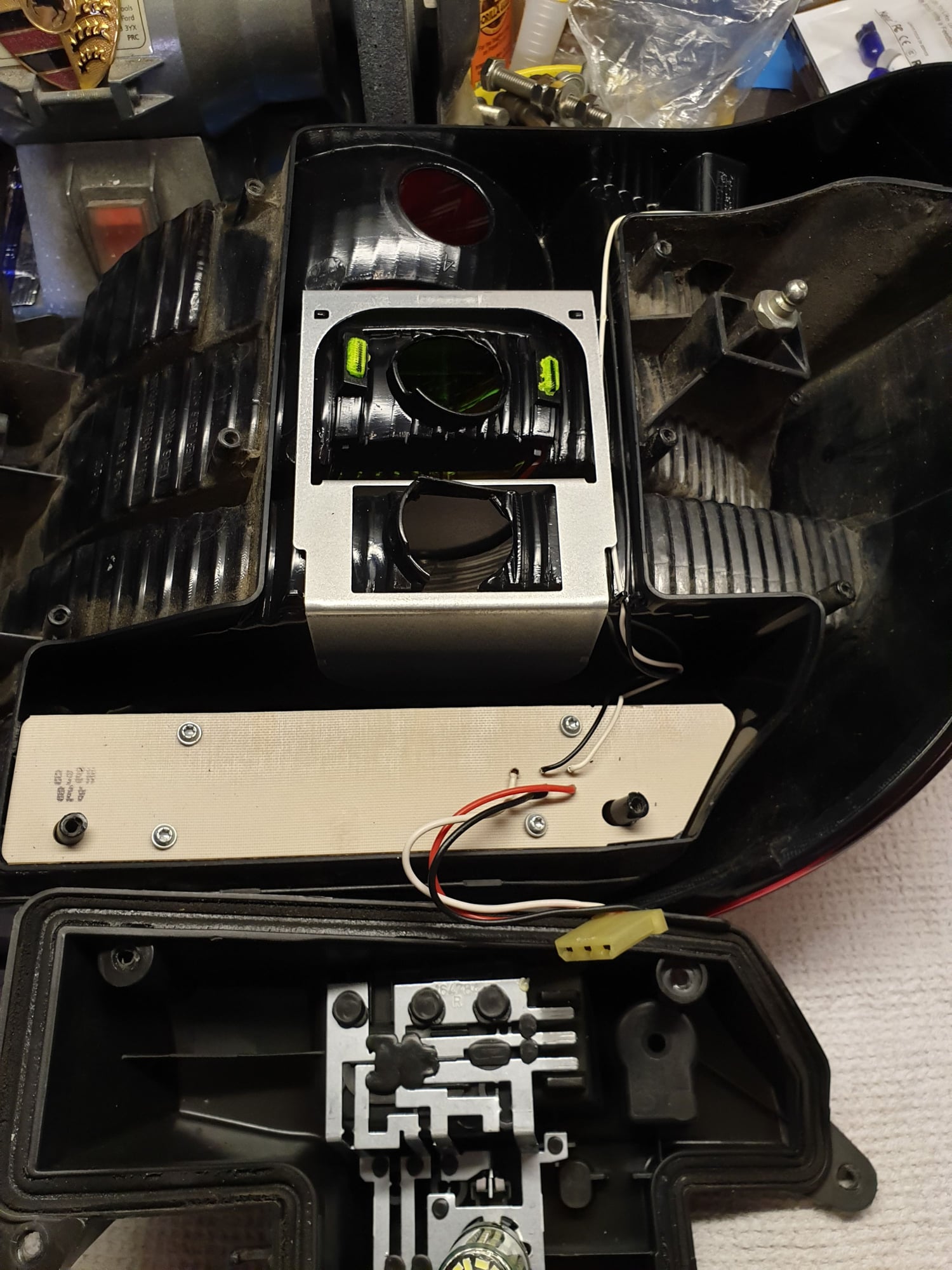
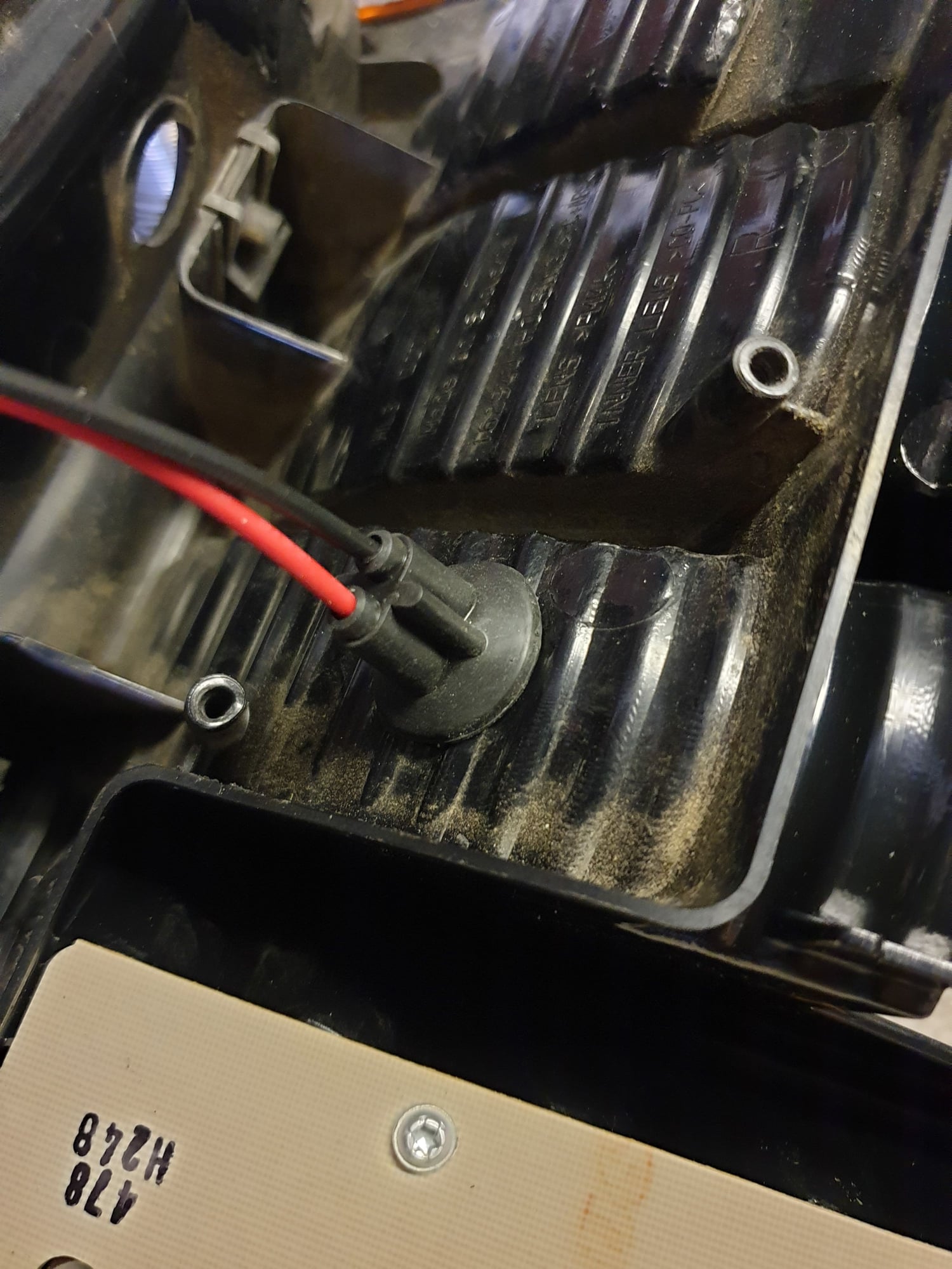
That's right - the original filament bulb is replaced by the LED and they only get slightly warm, especially considering that they are normally only switched on for a few seconds at a time. They are built on an aluminium substrate so radiate any heat very effectively. Also they are not really that close to the lense either. You can just about see the three LEDs behind the clear lense.

 06-01-2019, 08:27 AM


")


