When you click on links to various merchants on this site and make a purchase, this can result in this site earning a commission. Affiliate programs and affiliations include, but are not limited to, the eBay Partner Network.
Below is the parts I used in the videos posted above. I took this directly from the description of my video. I leave links and part numbers to all of the parts I use in each video.
Below is the parts I used in the videos posted above. I took this directly from the description of my video. I leave links and part numbers to all of the parts I use in each video.
@DIYDanCars What are the Diverter Valves on you list for? Thanks
Jeff
They are the Audi/VW "710P" diverter valves which are suppose to hold boost better than the older style. I added them to the list because to replace the passenger side DV is a 2 minute job with the fender liner removed. The driver side is a little more involved to do, i'll say its 10 minutes instead of 2 minutes, but well worth the effort. Judging by my seat of the pants dyno replacing both DVs made a healthy improvement to my car.
Below are my notes and suggestions for others looking to replace the front upper and lower control arms on a 2006 CTT. While I did not need to replace the air spring, air spring o-rings, front strut gaiter/dust boot, and/or sway bar links, it would have been no meaningful additional work to do such. I’ll also add that replacing the diverter valves (for turbo models) would also be a good job to consider while things are disassembled, as would cleaning the cowl drains and potentially replacing the torque strut and brake booster vacuum lines.
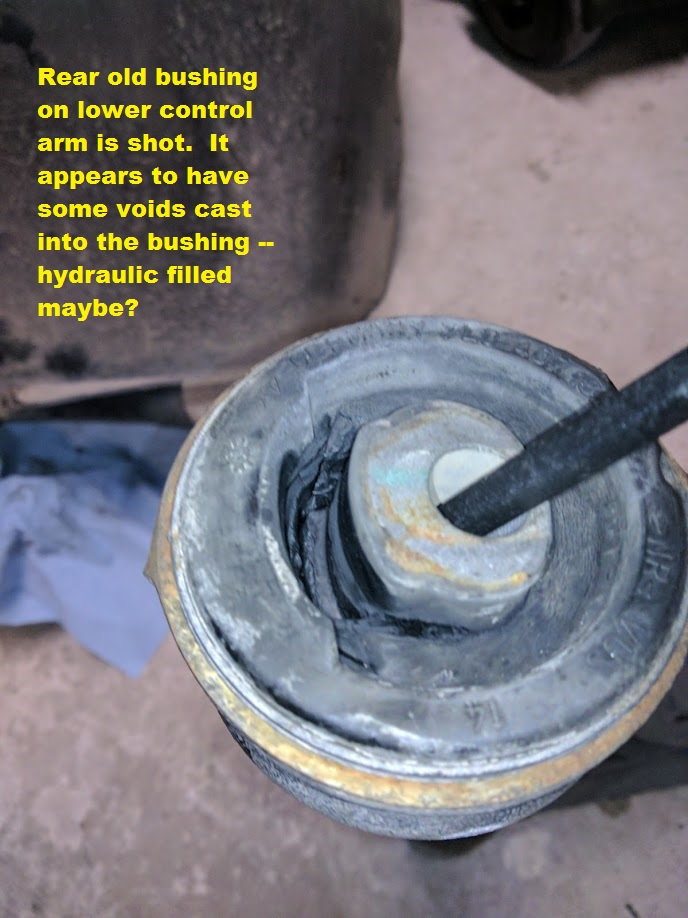
Interestingly, I didn’t really notice any handling issues beforehand, but upon replacement, it was clear that the old, rear lower control arm bushings were also shot. While the suspension was definitely tighter afterwards, it wasn’t as transformational as with other marques of cars I’ve owned (replacement control arms always made BMWs feel like new), but hopefully my tire wear issues will be fixed.
Assuming “no whammies,” you can get the whole thing done in a long day – figure ~6-8 hrs for just the front suspension bits. The upper control arms require more steps/disassembly, so figure 4-5 hours for those, and 2-3 hours for the lower control arms.
SPECIAL THANKS/ADDITIONAL RESOURCES
Special thanks again to DIYDan who did a YouTube video of this process. I watched it a couple times and found it hugely useful and inspiring to give this a try:
Arnott, a manufacturer of replacement air springs, has some good videos and written instructions on how to remove/replace the air strut assembly — check the Installation Resources tab on this page: https://www.arnottindustries.com/a-2...yenne-9pa-suvs
I recommend that you review all the above, in addition to my thoughts below which have been organized for greatest efficiency in getting the job done.
SAFETY
The Cayenne is quite heavy, suspension parts are quite heavy, and many of the fasteners/parts for this job require a lot force to remove/reinstall. There’s an endless number of ways you can hurt yourself doing this job – I actually consider it one of the more dangerous jobs you can DIY. Use extreme caution and planning, particularly with respect to where you put your body – I take no responsibility for your actions.
While not an exhaustive list of safety considerations:
1) DO NOT USE A JACK TO SUPPORT THE CAYENNE WHILE WORKING – JACKS ARE FOR LIFTING, NOT SUPPORTING. Use high quality jack stands to support the Cayenne at the front jacking points. I used 3 ton/ea, flat-top ESCO stands. I find them to be quite strong and stable: https://amzn.to/2TIAFLA
2) Use a jack to assist you in lifting/compressing the suspension while you work on it, but DO NOT PUT YOU BODY UNDER ANY PART SUPPORTED BY A JACK. If the jack slips or falls or bleeds down, you do not want to be in the path of whatever it’s supporting.
3) Don’t use fingers/hands to align holes or lever parts – you could get a nasty pinch or much worse. Use pry bars and/or screwdrivers to move/align heavy parts and keep your fingers and hands as out of the way as possible.
4) Wear gloves and eye protection and boots (sorry, Dan).
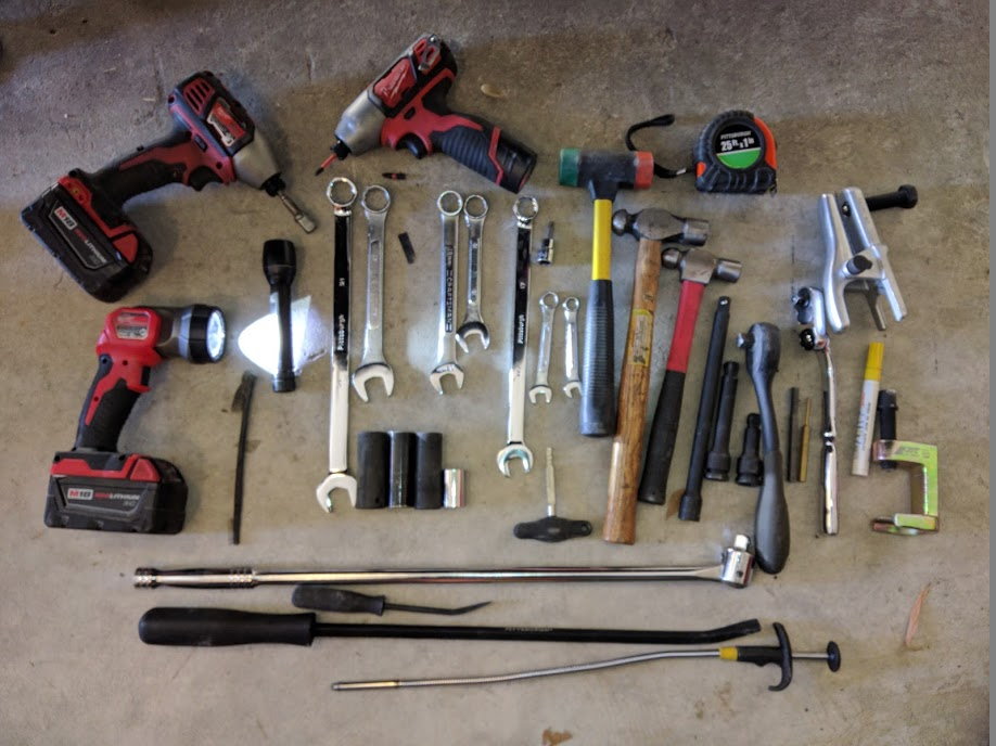
SPECIAL TOOLS
This job requires several tools you may not already own. Here’s a recommended list:
- Two 21mm wrenches – One of those wrenches can be “normal”, but you really want at least one of them to be “extra-long” and preferably box ended for leverage/torque. Ideally, you also want it to be a ratcheting box end wrench as you’ll be undoing/reinstalling self-locking fasteners and they don’t spin off/on with your fingers, hence you’ll spend a lot of time moving the wrench a quarter turn at a time to remove/install nuts in tight spaces. You don’t have to have a ratcheting wrench (I didn’t), but it’s much more tedious without one. Example of a good wrench for this job: https://amzn.to/2tgjkxZ
- Two 18mm wrenches – Same rules/suggestions as for the 21mm wrenches: One long and one ratcheting wrench. Example of a good wrench for this job: https://amzn.to/2SMci2F
- Large Ball Joint Separator (or pickle fork) – If you don’t want to modify anything, the “right” separator to get is the JTC Tools 1258: https://amzn.to/2WTK8le. You need one that’s at least 25mm of “throat width”. I bought its little brother (JTC 1257), but it had to be modified by grinding about 1mm all the way around the “throat” of the separator with a die grinder. I also used this one, but it too required modification: https://amzn.to/2TIqGWA — take a look at the comments to see a picture of the modification that was needed for the Q7 (and Cayenne). You could also use a pickle fork if you are a barbarian.
- Porsche/VW connector release tool -- This tool is super helpful to release certain plastic electrical connections (like the ones on brake pad sensors): https://amzn.to/2SDUGFY. To use it, insert the two protrusions on the end of the tool into the square holes on the electrical connector; squeeze the connector together (i.e, tight) which helps to “unstick” the locking tab inside; and then pull on the handle of the tool in the opposite direction of release. The tool should pull the locking tab release and separate the connection in one go.
- Selection of Torx bits for small fastners on fender liner and engine splash cover.
- Extended reach “grabber claw” tool that you usually use to pick up stuff you dropped into the engine bay. In this case it’s also useful to get a couple bolts started. Like this: https://amzn.to/2S1jtzs
- Big and small pry bars: The set from Harbor Freight worked fine for me.
- 10mm, 13mm, 16mm (or 5/8”) wrenches and socket for various bolts plus socket extensions.
- A paint pen or sharpie, preferably in a color other than black.
- You may also need a small stool or step ladder to reach over the fender and into the cowl area when the car is lifted.
Here’s a picture of the tools I used:
And here's a picture of the Ali-Express die grinder I used to open the "throats" of the ball joint separators:
I’ve purposely left parts of this section a little vague – If you have any questions about how to safely lift your car and remove the wheels, you should probably not be attempting this repair.
1) Pull into your work space and , if you have air suspension, put the Cayenne in Normal height mode and lock the suspension by holding the height lever up for 10 seconds until you get the “Suspension Off” notice on the dash
2) Measure the distance from the center of your front wheels to the bottom edge of the front fender. I measured ~18 inches from center to fender lip – yours should be similar. Note that we don’t need a high accuracy measurement.
3) If you are replacing the upper control arms, now (before your jack up the car) is a good time to remove the windshield wipers and cowl using the instructions found here: https://bit.ly/2N0pPOp. If you’re only doing the lower control arms, you can skip this step.
4) “Crack” the lug bolts on the front wheels, but do not remove yet.
5) If you have a lift, use it with pride. Otherwise, you need to jack up the front of the car and put it on jack stands at the lifting points behind the front wheels. Note that I jacked each side from the respective subframe under the engine so that the jack would not interfere with the stand placement. Make sure the car is supported equally on both sides and that its stable.
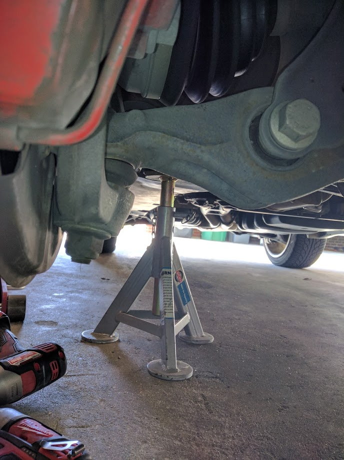
6) Once the car is safely supported on jack stands, finish removing the front wheels.
Here’s a shot from the front showing the car resting safely on a heavy duty jack stands at the lifting points behind the front wheels. The other side looks the same – both wheels are off and the car is equally supported, stable and ready for work.
7) Now is a great time to mark the position of the eccetric bolts/washers that secure the lower control arms to the subframe (Bolts "F" in the pictures below) – there are 2 eccentric bolts heads and 2 eccentric washers on each lower control arm. There may already be indexing marks that work, but if not, use a sharpie or paint pen to index the washer to the surrounding subframe bracket. You will want to be able to adjust these parts back to their original position when reassembling so that your alignment won’t be terribly off post-repair.
8) Now is also a great time to spray some rust penetrant on all the ball joints nuts and on the all the nuts and bolts that go through the lower control arm. And then say a prayer to the DIY wrenching Gods that you won’t have any issues removing them.
9) While the rust penetrant is doing its magic, go back up top and remove the plastic beauty covers surrounding the perimeter of the engine by turning the � turn plastic fasteners and removing the rubber hood gasket that surround the engine bay.
10) Ok, back under the fender – it’s time to “crack the nuts.” We need to make sure the suspension bolts are going to budge before going any further. Otherwise you potentially risk getting stuck without the right tool. Loosen (but do not remove yet) the following:
A. Little, upper control arm to steering knuckle ball joint (18mm)
B. Sway bar to sway bar link bolt (the one on the bottom) (18mm x 2)
C. Sway bar link to air strut bolt (18mm x 2)
D. Strut to lower control arm bolt/nut (18mm x 2) – NOTE: Be sure to loosen the nut side, not the bolt head side.
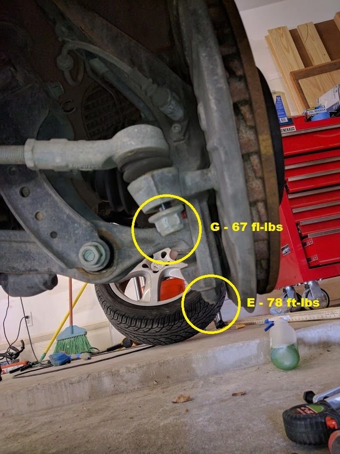
E. Big, lower control arm to steering knuckle ball joint (21mm)
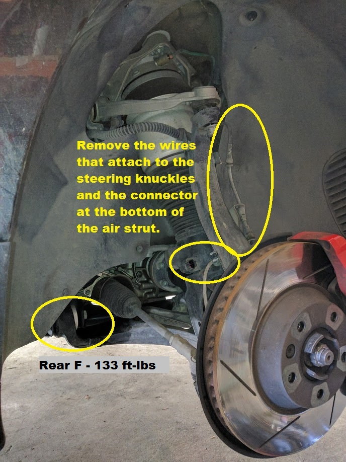
F. Both lower control arm to subframe bolts (21mm x 2) – NOTE: There are two eccentric bolts per lower arm and they are really tight. Use a long, quality box end wrench and LOOSEN ON THE NUT SIDE ONLY. If you try to loosen from the bolt head side you will damage the bolt or the eccentric washer.
G. Tie rod to steering knuckle ball joint (21mm) – this is not absolutely required, but I found it useful as detaching the tie rod allows you to move/position the steering knuckle
NOTE: Bolts/steps A - D above are required for removal of the upper control arm and/or strut; Bolts/steps D - G are required for the lower control arm replacement.
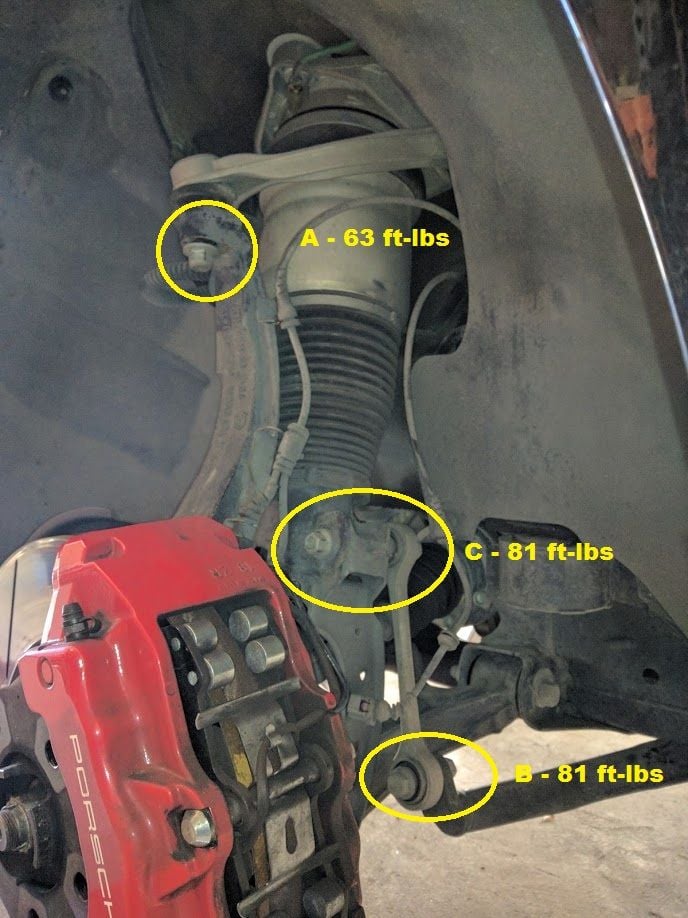
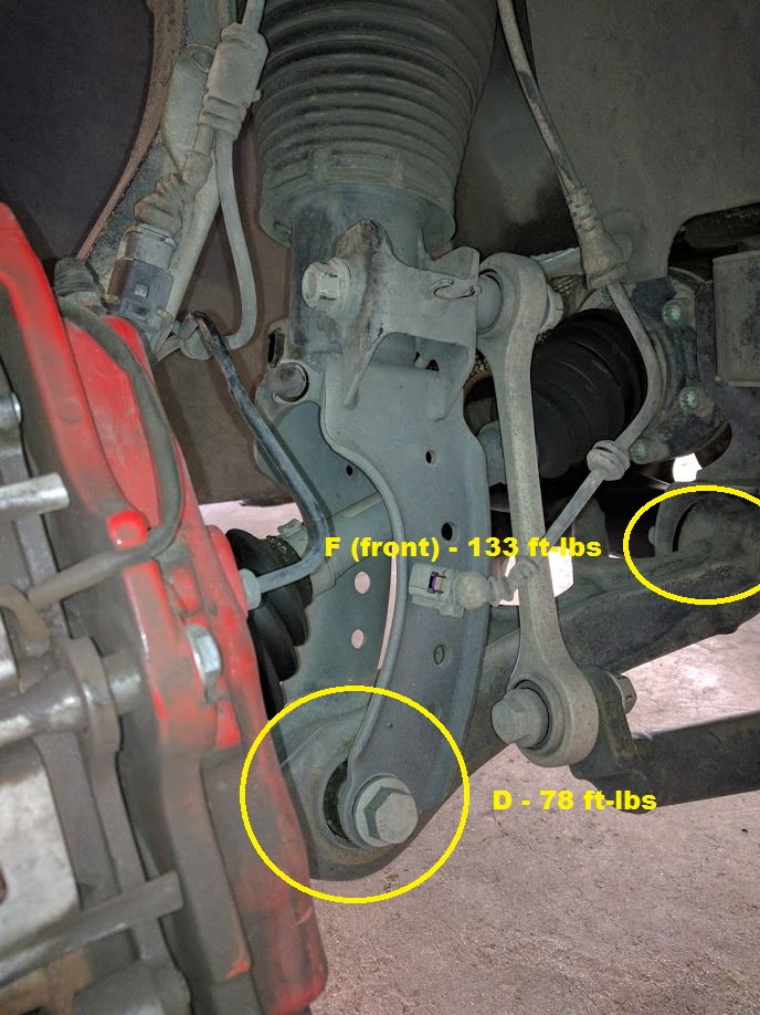
Here’s a couple pictures of the nuts and their locations using the lettering scheme above.
If you were able to loosen all of those nuts, congratulations, you are substantially through the most challenging part of this process. If you couldn’t loosen any of the bolts, it’s time to consider whether you need more/better tools or want a pro to tackle this.
UPPER CONTROL ARM REMOVAL/REPLACEMENT
This section assumes you’ve already got the car prepped per the “SETUP/PREPARATION” section above.
11) Starting from the top of the car, if not done already as per Step 3 in the prior section, remove the wipers and cowl
12) Optional, but recommended: If you are replacing the engine torque strut and/or the brake vacuum hose, now is a good time to remove the vacuum pump and torque strut as removing both will improve access
i. Vacuum pump: Undo the power connector and clamp/rubber connection from the pump. Remove two 10mm bolts and lift out the pump. That will give you more access for the torque strut and for the strut mount bolts
ii. Torque strut: Remove the engine torque strut using a 12mm triple square socket and a (15/16/17mm?) socket on the engine mount. The fender side bolt can be accessed with a socket wrench.
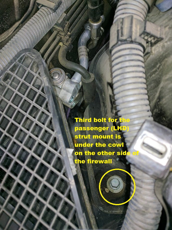
Here’s a picture of the passenger (RHD) side area around the vacuum pump/torque arm (both removed) showing 2 of the 3 bolts that hold the air strut mount. The second picture shows the location of the third bolt on the other side of the fire wall under the cowl that was previously removed.
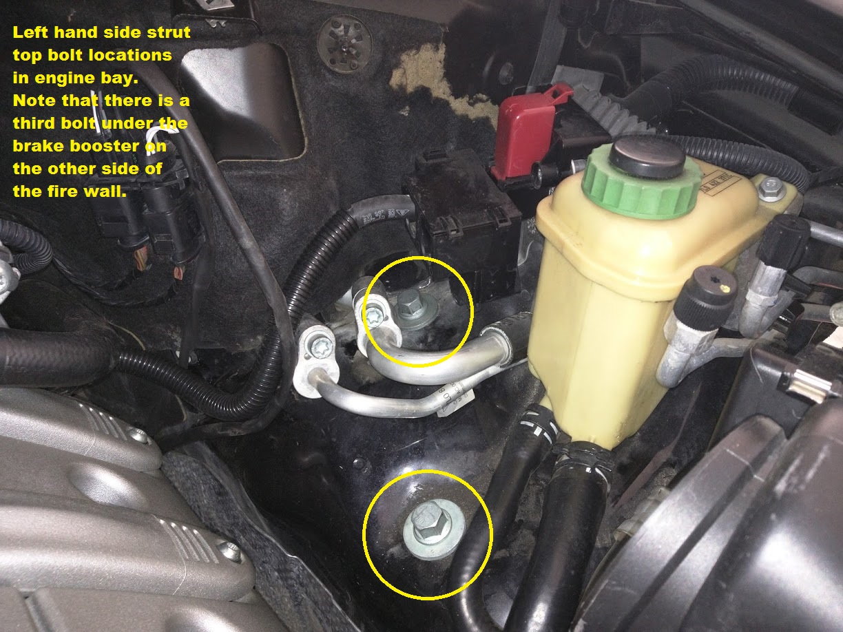
13) Using a 16mm or 5/8” socket on a long extension, remove two of the three bolts that hold the air strut mount. They shouldn’t be terribly tight. I recommend removing the two bolts closest to the firewall (one on either side) – the remaining bolt (closest to the front of the car) is pretty obvious and easy to get a wrench/fingers on.
The driver's side (LHD) looks like this:
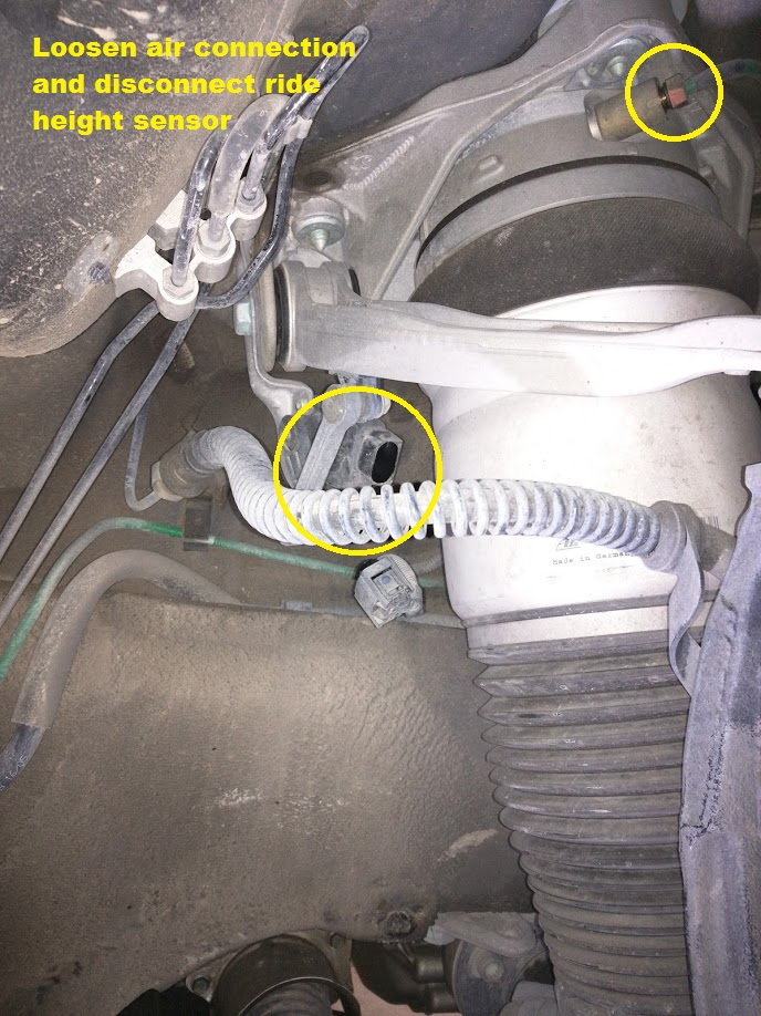
14) Back under the fender, use a 10mm wrench to loosen the smaller air line fitting at the top of the air strut. You should hear air escaping – you don’t need to undo it all the way yet. Let it bleed pressure.
15) Unplug the ride height sensor electrical connector.
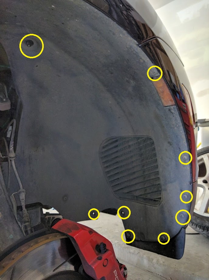
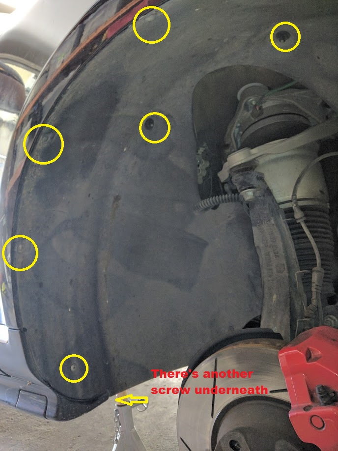
16) Remove the inner fender liner. This is NOT REQUIRED FOR THE LOWER CONTROL ARMS and I’m not 100% sure this is absolutely required to do the upper control arms, but most instructions seem to suggest that you do it (so I did). Removal is fairly straight forward, just undo the two 10mm plastic nuts and a bunch of torx screws – don’t forget the one that underneath the rear edge of the liner, back by the jacking point. With all the screws/nuts removed, pull the inner “flaps” of the liner (on either side of the air strut) downwards and outwards with some force. This will cause the two metal studs that secure the top of the liner to be pulled up through the holes, which will then free the liner to move backwards in the wheel-well which releases it at the fender edge. That’s the best I can do to describe a tricky process. Good luck.
Here's some pictures showing most of the fender liner screw locations. There's a couple on either side of the air strut that are not shown.
17) Undo the wires that run down the steering knuckle by wiggling their rubber grommets out of the corresponding brackets. Also unplug the connector into the lower part of the air strut. You’re trying to free up slack so the steering knuckle can fall forward when your undo the top ball joint, as well as free the strut for removal.
18) Finish undoing bolt B (the swaybar to swaybar link) from step 10 above. You can leave bolt C (sway bar link to air strut) attached at this time as the swaybar link comes out with air strut when it’s time. Note that you may need to use a prybar or jack under the lower control arm to take pressure off this joint to get the bolts out of their holes. You’re dealing with a big spring – use caution as there could be stored force in the swaybar — watch your fingers!
19) It’s time to separate the upper ball joint. Undo the upper ball joint nut (A above), but leave the nut on the very end of the threads of the bolt. Now use your ball joint separator of choice on this joint. You may need to gently hammer the separator onto the joint if it’s tight and the boot is in the way – you want the separator bolt to be perfectly in line with the bolt on the ball joint. Tighten the bolt on the ball joint separator and get ready for the bang. I tightened my separator a good bit (probably 40- 50 ft pounds) and then proceeded to hit the cast steering knuckle gently with a ball peen hammer. Give it some more turns and some more hits with a hammer and eventually it will pop loose with noise of a gunshot. You’ll separate 5 more ball joints before you’re done, and it gets slightly less nerve-racking with time.
20) Once the ball joint is free in step 19, you can finish removing the nut from the joint and gently let the steering knuckle (and attached hub/rotor/brake assembly) fall to the outside of the car. Make sure no wires or lines get pulled or pinched.
21) Finish removing the air line to the top of the air strut.
22) At this point, your air strut should only be connected at the top by one bolt in the engine bay, and by the bolt through the lower control arm at the bottom. Remove the nut on the lower bolt, but leave the bolt running partly through the strut/lower control arm to keep the strut supported while you remove the last of the upper mount bolts in the engine bay – the top of the air strut may drop a bit, but shouldn’t fall out. Back under the car, with the last upper mount bolt removed, I was able to remove the final strut to control arm bolt and let the air strut rest on the half-shaft axle below.
23) With the steering knuckle out of the way, remove the air strut top-first, by pulling the top toward you and then lifting the strut out of the wheel well. Be careful not to snag any wires or lines.
24) With the air strut out of the car, you can remove the upper strut mount from the air strut by slowly loosening the 4 bolts on the top of the mount. NOTE: There could still be residual air pressure in your air spring – use caution. I undid each bolt by only 1/8” first in order to release the air pressure in a controlled manner. Once you’ve confirmed there’s not more air leaking out, finish removing the four bolts.
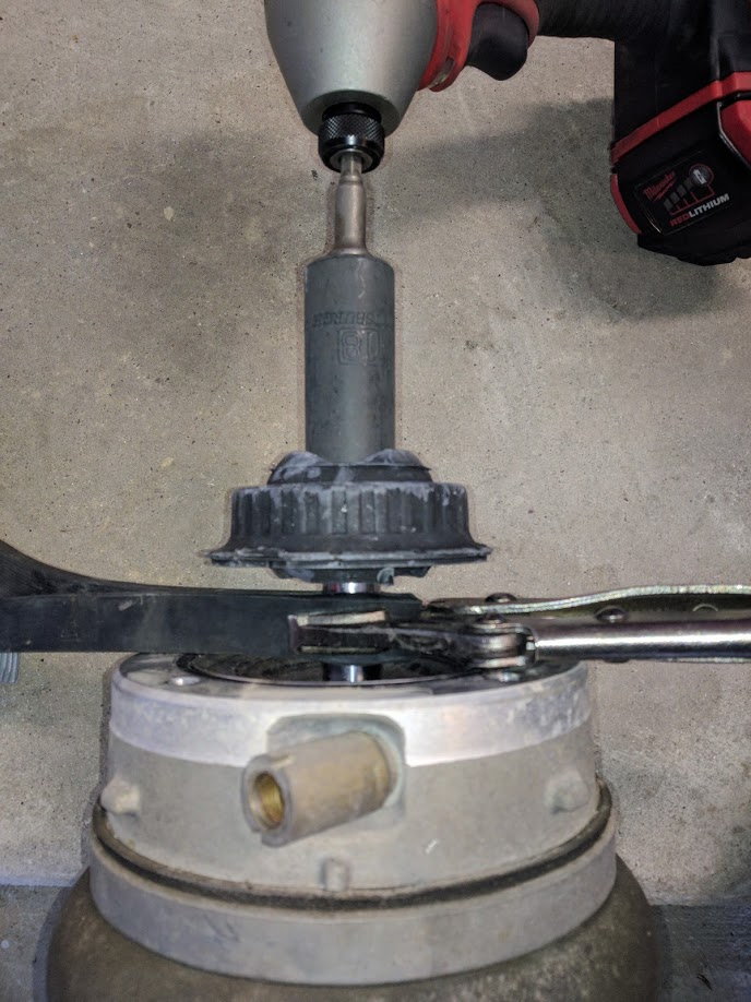
25) Underneath the upper strut mount is the strut top bushing (part number: 95534301810). Mine was actually in pretty good shape, but I’d already bought the parts so I replaced it anyway. To do so, I wrapped a rubber strap wrench around the polished shaft and then gripped it with vise grips. Be careful to not damage or mar the polished shaft. With the shaft securely held, I used an impact driver and a deep well socket to remove the nut that hold the bushing on the shaft. If you have deep offset wrenches, you can also use those to access the retaining nut. Torque to 44 ft-lbs.
Here’s a picture of me removing/reinstalling the strut top bushing:
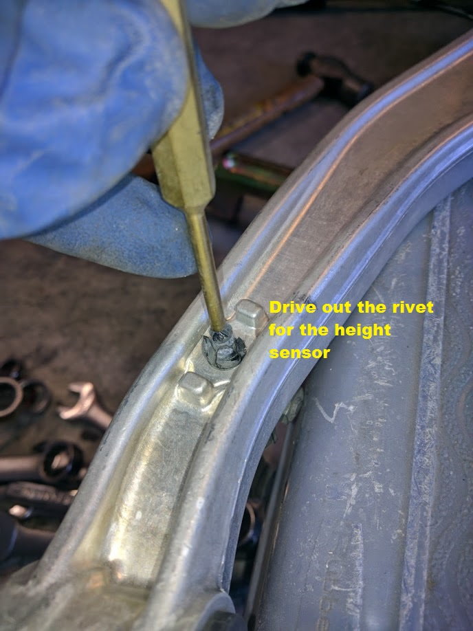
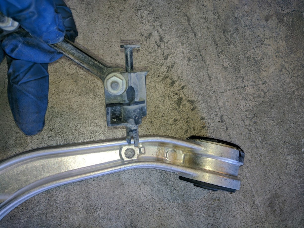
26) Now for the upper control arms. There’s really not much too it: Undo the two bolts holding the arms onto the upper strut mount. The ride height sensor needs to come off with the old arm and be installed on the new arm. You need to gently drive out the little rivet that secures the sensor to the arm so that it can be removed from the old arm. Pay attention to the orientation of the sensor when reinstalling – it only fits one way, but you can waste time if you put it on the wrong side. Reinstall the bolts for the control arm, but leave them loose until the upper strut mount has been reinstalled on the air strut/spring assembly.
Here’s a couple picture of the process of removing the sensor from the arm – driving the rivet out and then removing it from the arm:
27) Although I didn’t do it, you can also replace the air spring, top and bottom air spring orings, and/or gaiter/dust cover at this time. See the Arnott website for more detailed instructions if you need them. It’s actually pretty simple – just make sure you keep the work clean and don’t damage the shaft or sealing surfaces. My parts were in very good shape so I didn’t bother, but I did clean and lube (with dielectric grease) the top oring before reassembling all the pieces and tightening the 4 bolts on the top of the upper strut mount.One other thing: If you’re replacing the sway bar links, now is a good time to replace the old one and attach the new one to the bracket on the bottom of the air strut. Don’t worry about torqueing the link right now – you’ll do it when it’s installed on the car.
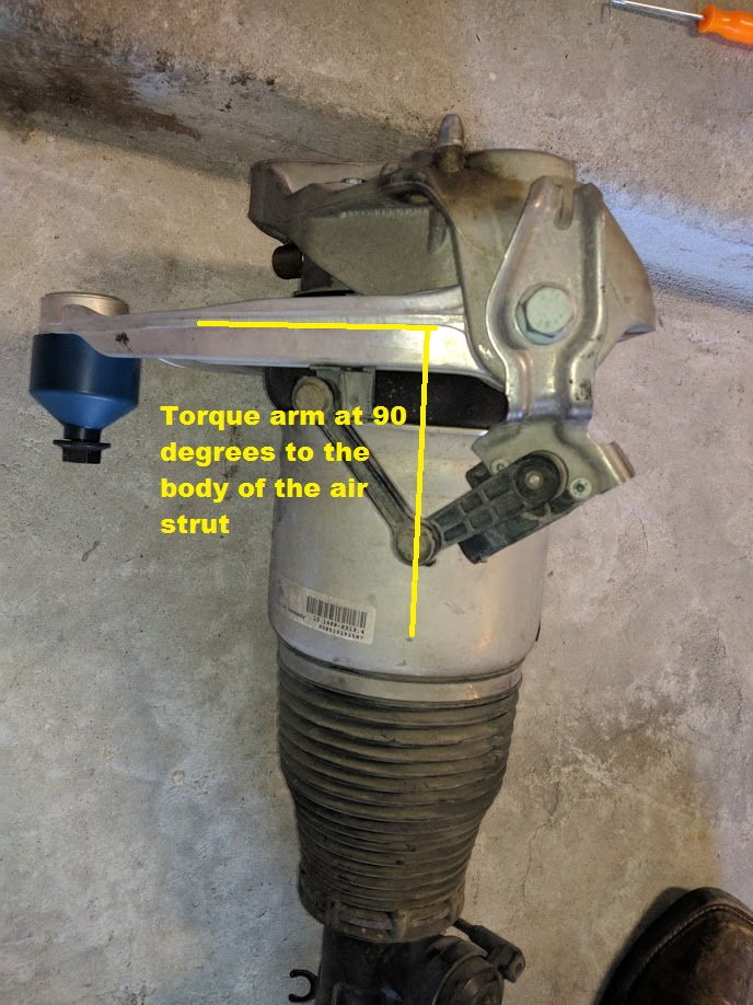
28) Lastly, you need to re-torque the upper control arm with the arm perpendicular (90 degrees) to the air strut body – that’ the resting position in the car at the normal ride height. The factory spec is 37 ft-lbs initial, but 90 degrees additional for new bolts. I reused my old bolts and torqued to 45 ft-lbs.
Here’s a picture of mine reassembled with new control arms and torqued such that the arms sit perpendicular to the strut at rest.
29) Reinstallation of the air strut wasn’t too bad. “Stab” the lower forked end over the half-shaft and swing the top up into the wheelwell. Be careful not to catch any wires or hoses while reinstalling. Once the strut is inside the wheel wheel, lift the assembly up and push the long bolt through the hole in the bottom of the strut and lower control arm to hold it in place. Don’t fasten this bolt yet, as you’ll need to undo it again for the lower control arm replacement.
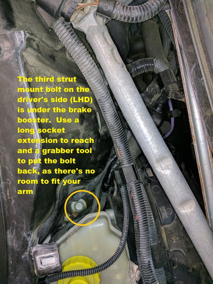
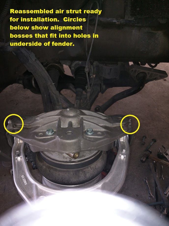
30) Using a jack under the lower control arm, gently raise the lower control arm and guide the strut mount up to the underside of the fender. You’ll notice there are two locating bosses on the top of the upper strut mount which mate with holes in the fender to get it in the right position. With the strut mount in the right spot (and supported by the jack from below), go back to the top side and reinstall the 3 bolts that secure the strut mount to the fender and torque to 37 ft-lbs. I used a remote “grabber claw” tool to help thread the bolts into the deep space behind the firewall (under the cowl).
Here’s a picture of my air strut just prior to reinstallation, showing 2 of the 4 strut top bolts that seal the air spring, and the 2 locating bosses that match up with holes in the fender. Also note that the steering knuckle is back and out of the way and you have a clear line of sight to “stab” the bottom fork of the strut over the axle shaft and control arm.
31) Reattach the upper control arm ball joint to the steering knuckle and put a nut on it to hold it in place. Also reconnect the sway bar link to the sway bar. Don’t worry about tightening them — we’ll do that later.
32) Reattach the air fitting, height sensor connector and push the wiring grommets back into their securing brackets. Reconnect the air strut plug. Final torque values are covered below.
Congrats, you’ve just replaced the upper control arm, air spring, dust cover, etc. You’re on the downhill side now.
At this point, you should have done all the preparation steps through #10 above. Unfortunately, I didn’t take a lot of pictures of the lower control arm replacement, so I highly recommend this video of the process if you have questions:
33) Finish removing the nuts and washers from the eccentric bolts that attach the control arm to the subframe. As previously mentioned, these nuts are self-locking and access is limited. I highly recommend a 21mm ratcheting box wrench to speed up the process. Also, keep the bolts and washers organized – you don’t want your marked washers ending up on the wrong bolts, you’ll waste a lot of time if you do – ask me how I know.
34) Once the nuts are off the eccentric bolts (Front and Rear "F" in pictures above), you need to remove/push the bolts through the bushings toward the front of the car. This is a bit tricky, but it can be done without any further disassembly. Use a hammer and drift and/or pry bars to help accomplish this. Note that the bolt head is eccentric and you may get more room under the steering rack boot if the bolt is turned a certain way.
35) Optional, but recommended: Following the same steps/tips as #19 above, use your ball joint separator to undo the tie rod end from the steering arm ("G" in pictures) and then fully remove the nut. This will allow you more access to get the lower control arm out in subsequent steps.
36) Following the same steps/tips as #19 above, use your ball joint separator to undo the lower control arm ball joint from the steering knuckle ("E" in pictures").
37) At this point, the lower control arm should only be connected to the car by the long bolt that goes through the bottom of the strut assembly (and somewhat by the ball joint which still pokes through the knuckle). Remove the strut bolt while supporting the arm. With the steering knuckle turned “out”, rotate the lower control arm forward and down to free the ball joint from the steering knuckle. It should come right out.
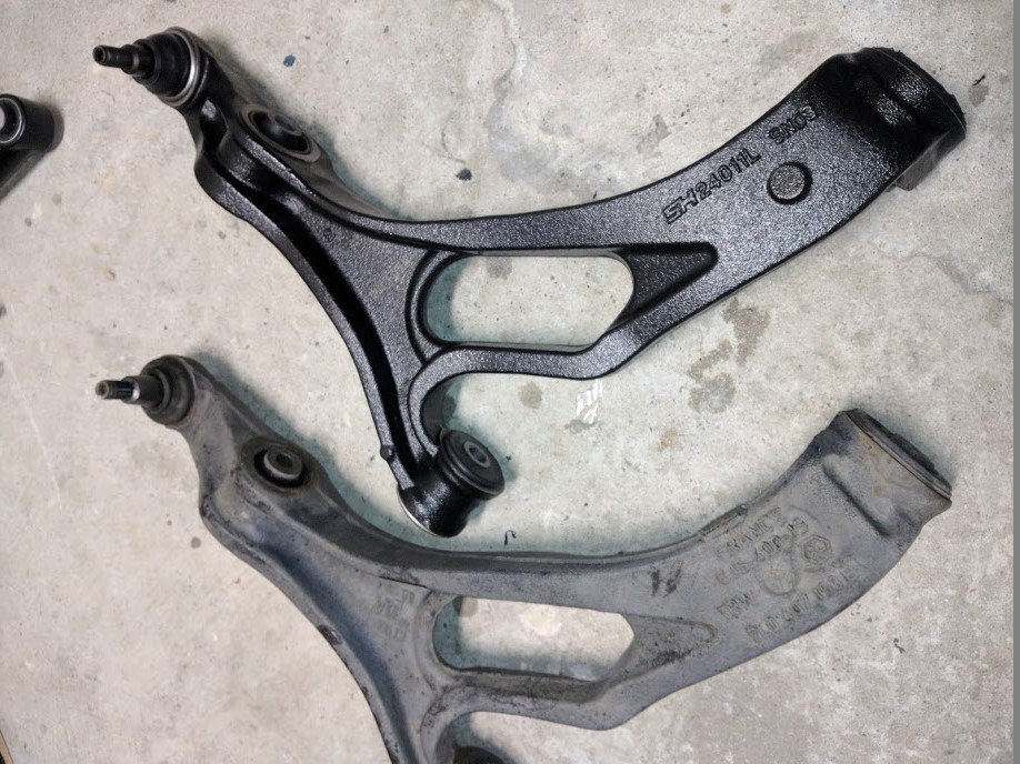
Here is a pictures of my old rear control arm bushing and a picture of my new control arm next to the old one. I bought these new control arms 2-3 years ago and can’t find a receipt or markings to indicate what they are, but they seem to be decent quality.
38) Installation of the lower control arms is the reverse of removal: Start by inserting/rolling the balljoint of the new lower control arm into the steering knuckle. Loosely thread a nut on the balljoint to keep it in place.
39) Using a jack, lift the new control arm back up into place, while using screwdrivers and prybars (and maybe a mallet) to align the holes for the bolts.
40) Insert the appropriate bolts in the holes. It’s worth noting at this point that my new lower control arms came with new nuts for all the bolts. The nuts are not identical and could fit in several places – study what you’ve got to make sure you put the right hardware in the right place the first time.
41) Double check that you’ve got the right eccentric bolts and washers in the right place before putting the nuts on. You should be able to turn the bolt and get both the bolt and the washer to line up on their respective marks – if so, you likely have a match. Carefully turn the eccentric bolts to line up the marks you previously made. Take up the slack on the nut on each eccentric bolt, but to NOT tighten them fully yet – they should be loose enough that you can still easily adjust the position of the eccentrics with very little force. We’ll tighten them shortly at “ride height”.
42) Make sure you reattach all ball joints, including the tie rod end to the steering knuckle.
43) Tighten all the ball joints to the following torque specs:
A. Upper ball joint: 63 ft-lbs
E. Lower ball joint: 78 ft-lbs
G. Tie rod ball joint: 67 ft-lb44) At this point, all the ball joints should be torqued and all bushings should have bolts through them that require torqueing. The suspension should be feeling tight already – if it’s not, check your work, you may have missed a bolt.
45) Using a jack, lift under the middle of lower control arm and raise the axle until it is at the “ride height” distance that you previously measured at the start of this project. In my case, the center of my axle was 18” from the bottom of the fender.
46) Staying clear of the parts suspended by the jack, recheck the position of the eccentric bolts ("F") you adjusted in step 41, and tighten the nuts (NOT THE BOLTS) to 133 ft-lbs. You will need to use a second wrench to hold the bolts stationary while you tighten the nuts. As I don’t have a suitable torque wrench for the limited space, I tightened it “to feel”, which in this case was the same as “I gave it all I got”.
47) With the lower control arm still supported at “ride height” by the jack, torque the remaining bolts to spec:
D. Strut to Lower control arm: 78 ft-lbs
B & C. Both ends of the Sway Bar Link: 81 ft-lbs48) Reinstall the inner fender liner. This is easier said than done. Replacement of the liner is on par with solving a Rubik’s cube – you can do it if you know the tricks, but it’s hard to explain. And it takes a lot of attempts. I would usually get the front corner started (and screwed) and would then wrestle the rest of it into place. Eventually, you’ll get it just right and it pops into place.
49) Double check all your work and put your wheels on and torque the bolts.
50) If everything looks good, you can remove the jack stands, but:
NOTE: THERE IS NO AIR IN YOUR FRONT AIRSPRINGS AND THE CAR WILL BE SLAMMED TO THE GROUND IF UNSUPPORTED. LIFT THE CAR AT THE SUBFRAME TO REMOVE THE JACKSTANDS, AND THEN GENTLY AND SLOWLY DROP THE CAR TO “NORMAL” HEIGHT AND THEN STOP AND LET THE JACK HOLD THE CAR.
Confirm that the engine bay is clear of obstructions and start the engine. Unlock the air suspension by holding the height lever up for 10 seconds, and then adjust the suspension to Terrain height to pump up the air springs again. Once they’re holding air/weight of the vehicle, remove the jack and reset the vehicle height to normal.51) Turn engine off and resume buttoning up the remaining items in the engine bay including the vacuum pump, torque strut, wipers, and cowl if you removed them.
52) Take the car for a careful test drive. There should be no looseness or odd noises in the front suspension.
53) You should take the car to get the suspension aligned – the new parts/bushings may not be dimensionally identical to the old ones which could accelerate tire wear or cause handling issues. I was pleasantly surprised that my steering/handling felt good upon reassembly, although I’ll get the alignment done anyway.
PARTS LIST REFERENCE (based on 2006 CTT)
- Upper Control Arm x2: (note, left and right are interchangeable): 95534102702
- Lower Control Arm Right: 95534101833 (or 95534101850 for the CTTS version)
- Lower Control Arm Left: 95534101733 (or 95534101750 for the CTTS version)Sway Bar Links x2: 95534306900
- Shock Mount Bushings x2: 95534301810
- Front Airspring Right: 95535840431
- Front Airspring Left: 95535840331
- Clean your cowl drains while the fender liners are out
- Replace your brake booster vacuum lines – requires wipers/cowl and/or torque strut to be removed
- Replace your diverter valves (turbo models only) – easier with the fender liners out
Here's a picture of the right side diverter valve (turbo model only):
Is the the steel spring suspension steps will be very similar to this? I think the top strut mounts need replacing on my car (clunks over small bumps), and I am thinking of doing upper control arms at the same time.
I'll let someone with a steel suspension provide the definitive answer, but looking at the instructions provided by Arnott on their steel conversion kits, it would appear that the key differences are that 1) you will have to use a spring compressor to remove and install the rubber strut top bushing, and 2) you wont have the airlines, orings, dust covers, and height sensor wires to deal with. All the suspension bolts and disassembly/repair process otherwise appear identical.
The 955/957 guide and video on CA replacement is almost 100% the same as the job on the 958 was. Primary differences were that on 958 the strut does not attach to the upper CA but rather the strut tower. I did not need to remove the wiper arm or wiper cowling at all, though I did remove the beauty cover over the fenders. Also some of the bolt sizes were different than they mentioned, and there was at least one 22mm nut I wasn't expecting to see (lower ball joint and a 12 point at that). Luckily I had a box end that fit or I'd have been screwed.
Just want to add it is possible to do without removing the wiper arms. I did so on our 955 Cayenne. I do remember thinking what a pain it was working blind, but small hands helped.
Other than that, replace all rubber stuff in one go. It is mot something you want to repeat any time soon.
I did/had done this work a few months ago. I was able to do the upper front control arms but when I went to tackle the lowers there was a bolt I couldn't budge. Took it to our local shop and they got it completed. I think it was only about $300 or so for the front blowers and the rear upper and lower. They had to use a 3/4 pneumatic impact to get the stubborn bolts. Ride and handling improved greatly. Roll before was noticeable, not so much now.

 01-18-2019, 02:40 PM