When you click on links to various merchants on this site and make a purchase, this can result in this site earning a commission. Affiliate programs and affiliations include, but are not limited to, the eBay Partner Network.
Boxster 986 '98 fuel pump relay - which pins are negative and positive
I need to check the relay with a multimeter, as the car won't start. Anyone know how should I connect the relay to the battery, which pins are positive and negative and which are the ones to connect with the multimeter? Thanks.
I need to check the relay with a multimeter, as the car won't start. Anyone know how should I connect the relay to the battery, which pins are positive and negative and which are the ones to connect with the multimeter? Thanks.
By not start I assume the engine cranks ok just doesn't fire?
Techs use a bypass relay to eliminate the relay. They connect "shop 12V" power to the fuel pump directly to ensure fuel pump has power and runs or doesn't as the case may be.
When my 2002 Boxster fuel pump quit that's what the tech did to verify it didn't run.
He knew the relay was ok because he loaned me his bypass relay which I used at home to confirm it wasn't the relay.
Messing around with the car's electrical systems is risky. A new relay isn't much so I'd be tempted to just buy a new one and try it. If it is not the relay box the thing and put it in the door storage bin for back up just in case.
From the Bentley manual: Operating fuel pump for tests (1997 - 2001 models).
To operate the fuel pump for testing purposes without having to run the engine bypass the fuel pump relay to power the pump directly.
Access relay panel 1 (above the fuel panel, left footwell) and remove the fuel pump relay. (Warning: fuse and relay locations may vary. See 97 Fuses, Relays, Component Locations.)
Using a fused jumper wire bridge terminals 30 and 87 (labeled 3 and 5 on the relay panel).
Make jumper wire from 1.5mm^2 (14 gauge) wire and include an inline fuse holder with a 15A fuse. To avoid relay panel damage from repeated connecting and disconnecting also include a toggle switch in the jumper harness. The fuel pump should run as soon as teh jumper wire is attached.
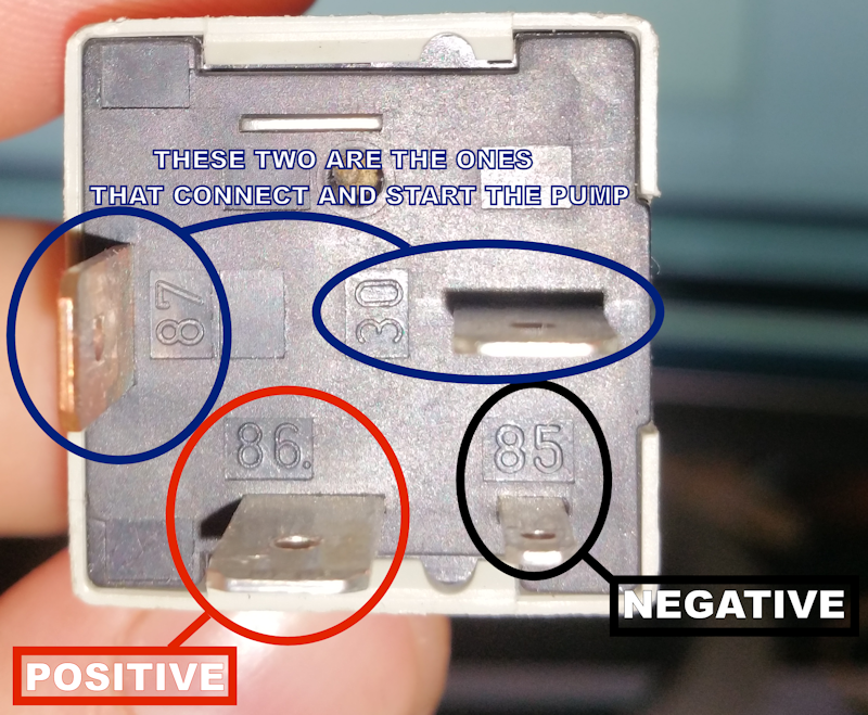
Yeah, I actually found that information eventually. For anyone who's interested the pins have numbers assigned to them on the relay:
- pin 85 is negative (smaller)
- pin 86 is positive (bigger)
- pins 30 and 87 let current through when connected to start the pump. These are the ones to connect the multimeter probes to.
This is how the relay looks from the bottom:
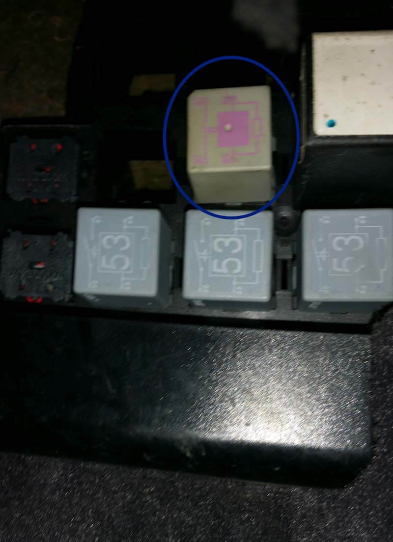
And this is how it's plugged, although I'm sure it only goes in one way:

 04-23-2017, 03:48 PM