
V8 Conversion
 06-12-2015, 11:23 PM
#61

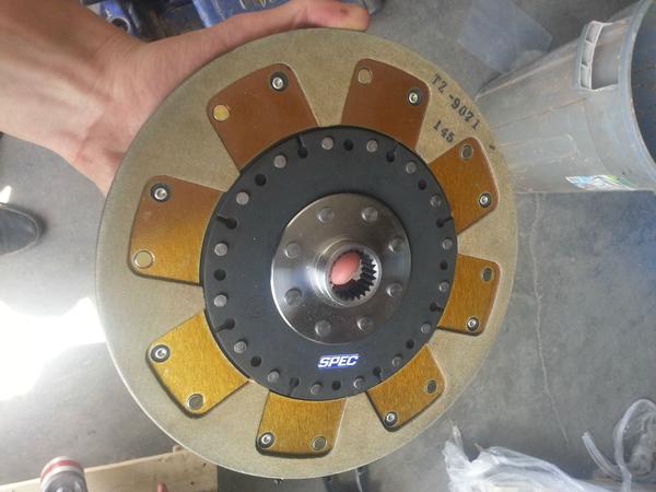
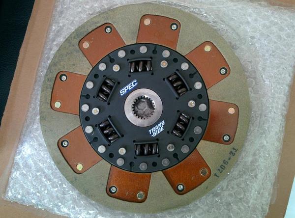
I can't thank the guys at SPEC enough for rebuilding my clutch disc. The store where I had bought it from miss advertised it as a sprung hub, when in reality it was a rigid design. Took only about a week to get my disc back. Shipping it back to the store for a refund would have sucked. Here's a picture of the old and new clutch disc.
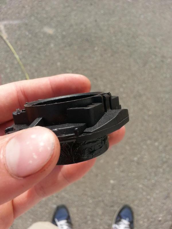
Instead of flexing, the plastic clip on the release bearing just sheared off when I put it in the clutch fork. Not sure if this was a defect, but the plastic seemed much more brittle than on the old one. I didn't want to take any chances on such a cheap part, so I called Downtown Porsche to pick up a replacement. The guy on the phone told me it would be $260 PLUS TAX! WTF?!?! The whole clutch kit cost me $620... At this point I decided that I'd rather keep my money. The old bearing was in pretty good condition, so I swapped out the plastic sleeve from that one. Not an ideal solution, but hopefully it will do. I did check the sleeve ID for wear and it was the same as the new one.
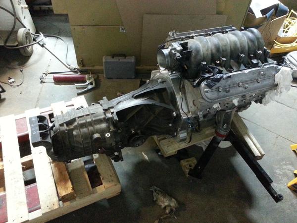
The tolerance on the SPEC splines seem to be much tighter than the OEM disc. Putting the transmission on was nearly impossible this time; we struggled for a couple of hours to get it on by hand. At first I thought we weren't getting it into the pilot bearing, but then I realised it was just the friction of the clutch disc splines (yes we did lube everything prior). Once we got some spline engagement, we put a few transmission bolts on and slowly tightened them diagonally. Each time I checked the gap using a vernier caliper to make sure the transmission was going in level.
Instead of flexing, the plastic clip on the release bearing just sheared off when I put it in the clutch fork. Not sure if this was a defect, but the plastic seemed much more brittle than on the old one. I didn't want to take any chances on such a cheap part, so I called Downtown Porsche to pick up a replacement. The guy on the phone told me it would be $260 PLUS TAX! WTF?!?! The whole clutch kit cost me $620... At this point I decided that I'd rather keep my money. The old bearing was in pretty good condition, so I swapped out the plastic sleeve from that one. Not an ideal solution, but hopefully it will do. I did check the sleeve ID for wear and it was the same as the new one.
The tolerance on the SPEC splines seem to be much tighter than the OEM disc. Putting the transmission on was nearly impossible this time; we struggled for a couple of hours to get it on by hand. At first I thought we weren't getting it into the pilot bearing, but then I realised it was just the friction of the clutch disc splines (yes we did lube everything prior). Once we got some spline engagement, we put a few transmission bolts on and slowly tightened them diagonally. Each time I checked the gap using a vernier caliper to make sure the transmission was going in level.
 06-12-2015, 11:28 PM
#62
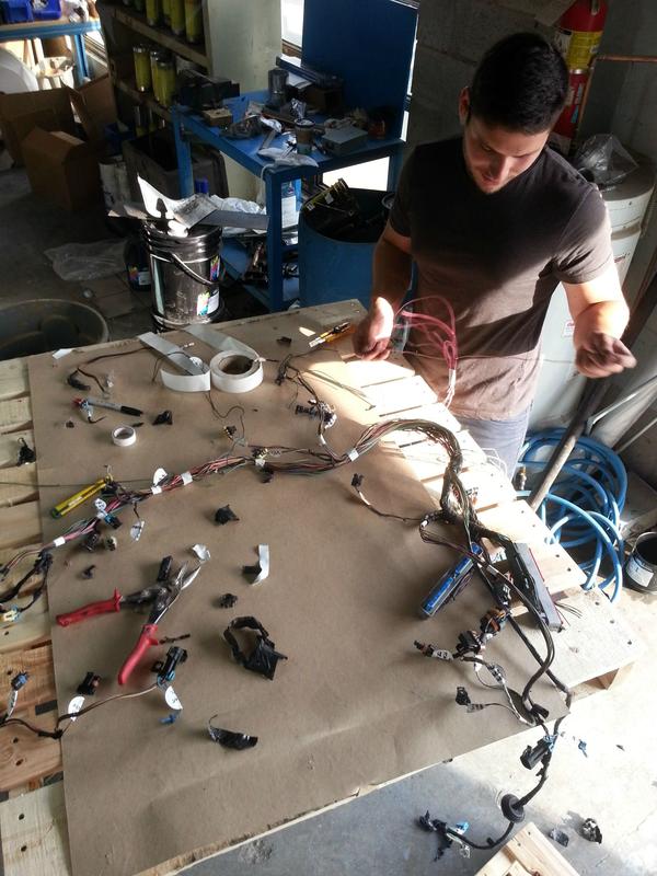
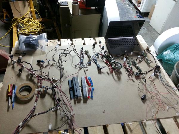
Wiring was definitely the most intimidating part of the build for me when I was doing the initial research, but it's really not that difficult once you have it all in front of you. For this build, I'm using a 2002 LS1 harness and LS1 PCM. There's tons of useful information and guides on this online, so don't be put off by the electrical work.
Here are some good links:
LS1 Harness diagram and Vacuum Diagram - MX-5 Miata Forum
LS1 harness: Start to finish - Third Generation F-Body Message Boards
Since the intake manifold is flipped 180 degrees, the original harness layout will no longer work.
Here are some good links:
LS1 Harness diagram and Vacuum Diagram - MX-5 Miata Forum
LS1 harness: Start to finish - Third Generation F-Body Message Boards
Since the intake manifold is flipped 180 degrees, the original harness layout will no longer work.
 06-13-2015, 03:06 PM
#64
Thanks boss, you are so insightful! I'm obviously not going to put on a seized clutch disc, I'm not stupid. The disc slides freely when it's on, I just couldn't get the transmission aligned perfectly and push it in by hand. Its not that easy to do with a twisted pallet jack and two hands. I guess now you will tell me not to work on cars unless I have all the right tools?
Last edited by martsink; 06-13-2015 at 10:08 PM.
06-16-2015, 12:34 PM
#65
Rennlist Member
Man I've wanted to do the same project. Half of your posts encourage me and the other half discourage me!!! LOL!
I'm interested in your cutting though. Have you found that it was in fact necessary? I was aware of having to cut the firewall based on Renegade's info, but the pics look like you cut out some more on the bottom.
I'm interested in your cutting though. Have you found that it was in fact necessary? I was aware of having to cut the firewall based on Renegade's info, but the pics look like you cut out some more on the bottom.
06-16-2015, 12:47 PM
#66
Man I've wanted to do the same project. Half of your posts encourage me and the other half discourage me!!! LOL!
I'm interested in your cutting though. Have you found that it was in fact necessary? I was aware of having to cut the firewall based on Renegade's info, but the pics look like you cut out some more on the bottom.
I'm interested in your cutting though. Have you found that it was in fact necessary? I was aware of having to cut the firewall based on Renegade's info, but the pics look like you cut out some more on the bottom.
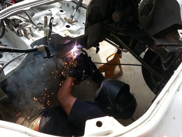
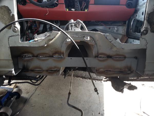
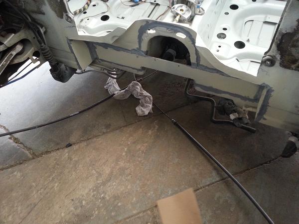
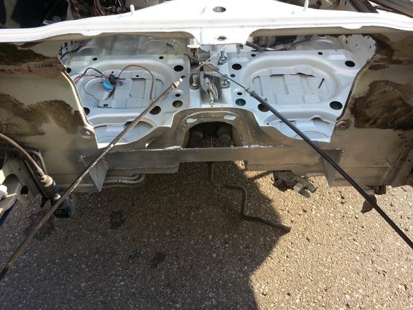
Unfortunately cutting is necessary or your harmonic balancer will not clear. Yesterday my buddy helped me weld in a reinforcement plate to make up for the structural metal that's been cut. I will post some pics later this week.
07-01-2015, 03:14 AM
#67
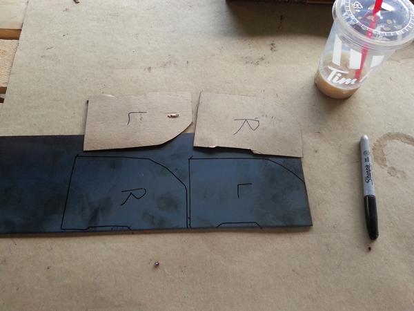
Today I finished on the chassis reinforcement plate that should be welded in to replace all the cut sheet metal. Renegade offers this plate for $135USD, but I suggest you just make it yourself. I picked up a 3/16" plate from a local metal market for around $15 CAD. There's really nothing to it. I also bought a can of weld thru primer, Spray Max 2k primer, and a seam sealer to protect it from the elements. I have a whole lot more info and pics on my blog.
07-01-2015, 03:14 AM
#68
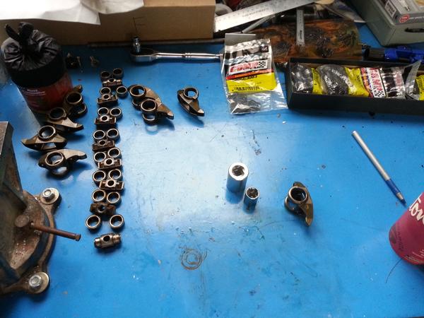
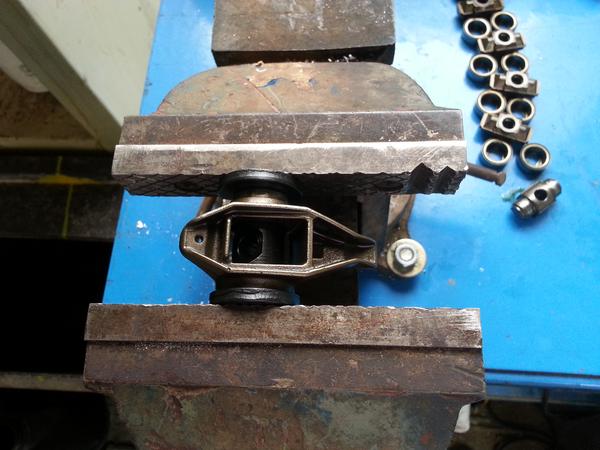
I've heard some bad stories regarding the stock rocker arm needle bearings, so I picked up a Comp Cams kit from Summit. The installation is pretty straightforward. The kit comes with two spacer washer so you don't crush the new bearings when pressing them in.
 07-01-2015, 03:15 AM
#70
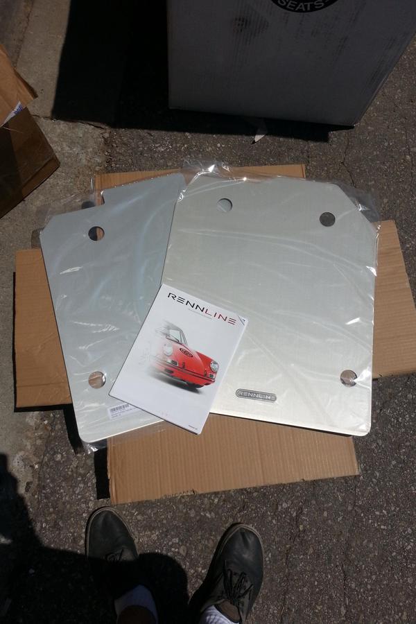
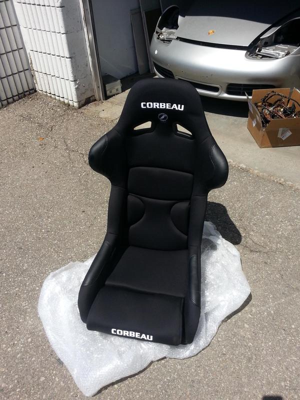
Last week I made another trip to the border to pick up more parts. I really hope that this is the last one, because I'm going broke way too quick. I gotta give special thanks to Rennline and Corbeau Seats for hooking me up with amazing deals on their products.
07-27-2015, 02:32 AM
#71
Hey guys! I haven't really had time to make detailed updates recently. We spent the last couple of weekends working on my friends 2005 E46 320. Dropped in a 330 engine and also changed one of his wheel bearings and an axle boot. In the process, we noticed that his rear subframe mounts are cracked, so this weekend we will be welding up the cracks and reinforcing the body. He also got a set of poly bushings to replace his old ones while we are at it.
The work on the Boxster is progressing nicely. The fuel lines and fuel regulator are installed, the brake vacuum line is hooked up, the stock throttle cable (from early Boxsters) is hooked up and working perfectly with no modifications, the harness is 90% finished, the alternator bracket is finished, the starter motor has been modified to fit. Next week I will be getting some parts to get the PCV valve installed, and hopefully the necessary parts to finish the intake and cooling systems.
The work on the Boxster is progressing nicely. The fuel lines and fuel regulator are installed, the brake vacuum line is hooked up, the stock throttle cable (from early Boxsters) is hooked up and working perfectly with no modifications, the harness is 90% finished, the alternator bracket is finished, the starter motor has been modified to fit. Next week I will be getting some parts to get the PCV valve installed, and hopefully the necessary parts to finish the intake and cooling systems.
07-27-2015, 02:33 AM
#72
I got my hands on a nice AD244 145 Amp alternator at a local scrap yard which I was planning to use for this build. This is an alternator that came on some GM trucks in the early 2000s, and it's a very popular upgrade for the LS1 guys. I made a bracket for it to match the new harmonic balancer, but once I put the engine in, I realised that it wasn't going to work. The mounting bracket on this alternator is just not ideal for this build. It would take a lot of modification to the alternator body in order to make it work, which I wasn't really too keen on doing.
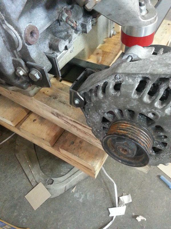
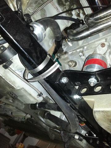
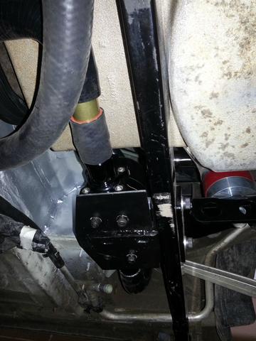
The original Porsche alternator on the other hand is a pretty easy fit. Renegade sells a bracket for around $140, but I think you can make one yourself in an afternoon with some scrap metal. The front bracket mates directly to the block and requires a spacer to align the pulley with the harmonic balancer (you will also need to file down the block in one spot where there is interference). The rear and the top brackets require a custom mount. Save yourself some trouble, and make the bracket while the engine is still out. Below are some pictures of what I made. These are not the finished product, I still need to buy proper bolts and give it a coat of paint.
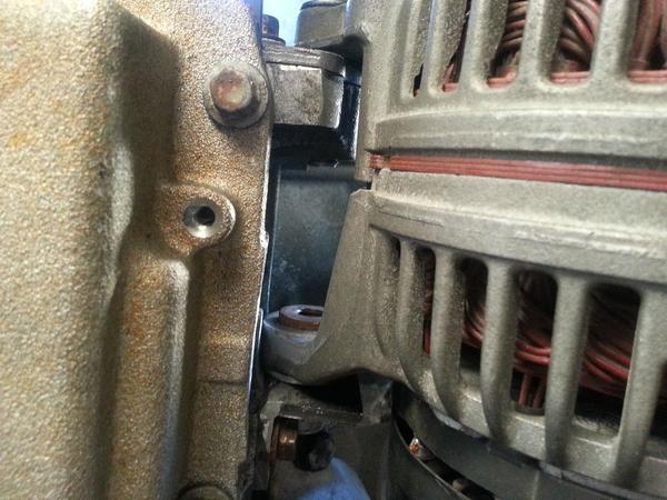
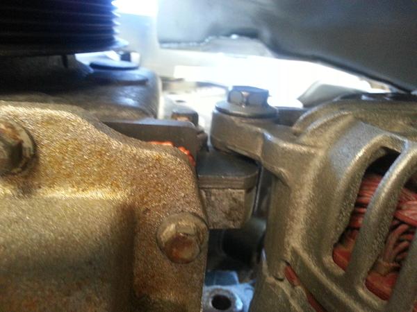
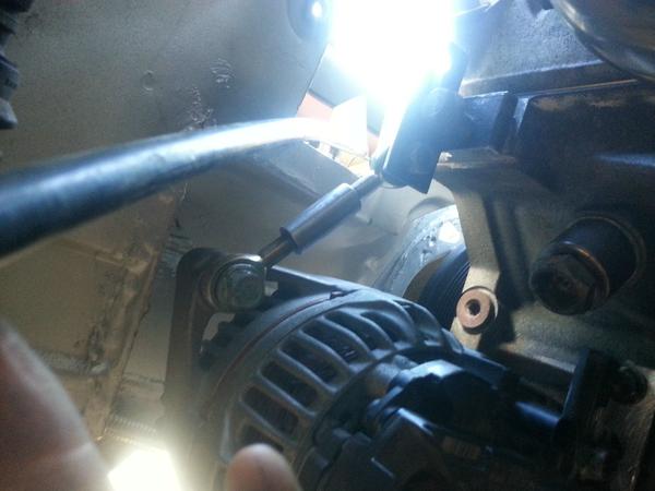
The original Porsche alternator on the other hand is a pretty easy fit. Renegade sells a bracket for around $140, but I think you can make one yourself in an afternoon with some scrap metal. The front bracket mates directly to the block and requires a spacer to align the pulley with the harmonic balancer (you will also need to file down the block in one spot where there is interference). The rear and the top brackets require a custom mount. Save yourself some trouble, and make the bracket while the engine is still out. Below are some pictures of what I made. These are not the finished product, I still need to buy proper bolts and give it a coat of paint.
07-27-2015, 02:34 AM
#73
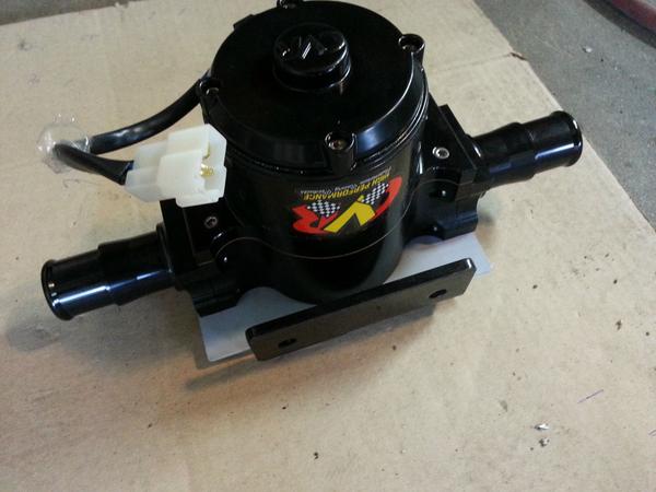
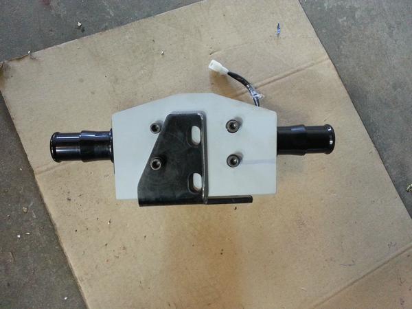
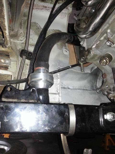
Renegade recommends using the Meziere water pump with their kit, but I decided to go with a local manufacturer called CVR. Their pumps are a little cheaper, but the build quality is still there. I've seen this pump used on other 911 swaps as well. The inlet/outlet orientation of this pump is not ideal for the Boxster, and given another chance, I'd probably go with the Meziere setup. I got an extra engine mount bracket with my Renegade kit (no surprises there...), which works out great as a pump mount. Below are some pictures of the bracket. Once I have the complete cooling system figured out, I will post more pictures of the pump location and hose routing.
08-22-2015, 03:34 AM
#74
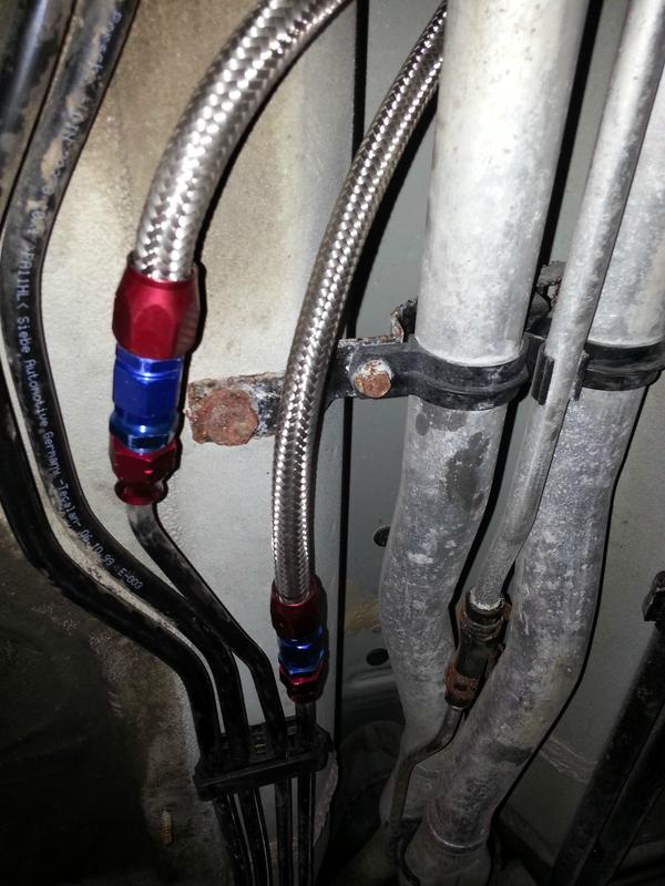
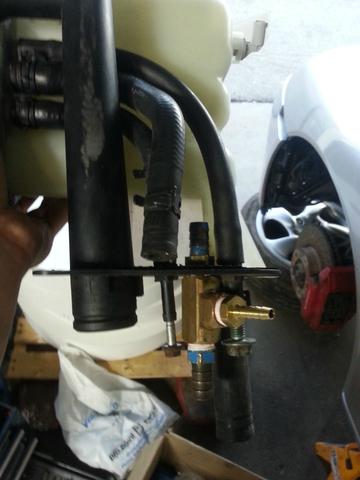
The fuel system is pretty straightforward, just buy some reinforced fuel line and compression fittings. If you have an LS1 or LS6 fuel rail, you will also need a fuel pressure regulator/filter. The GM regulator mounts perfectly in the old location of the Porsche fuel filter. I cut the fuel lines just before the filter and used -6 AN compression fittings to transition to a flexible reinforced line.
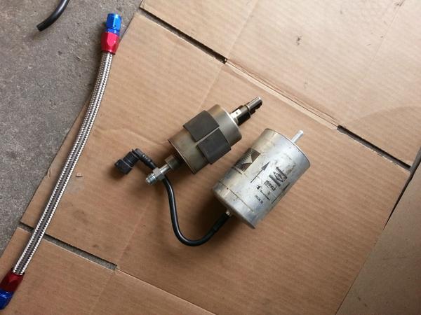
GM fuel filter/regulator on the left, and Porsche fuel filter on the right
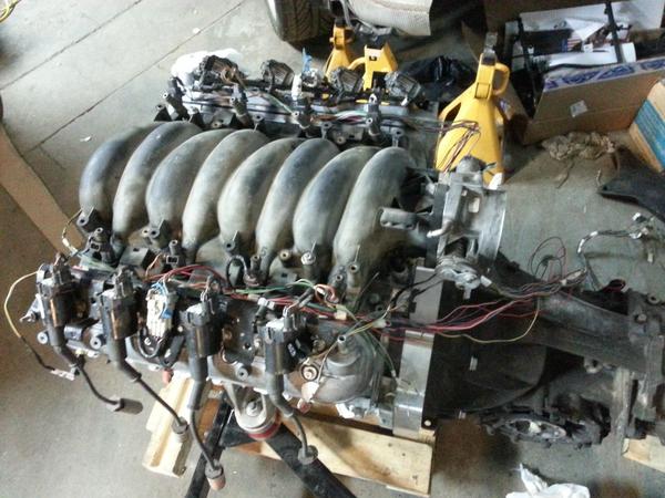
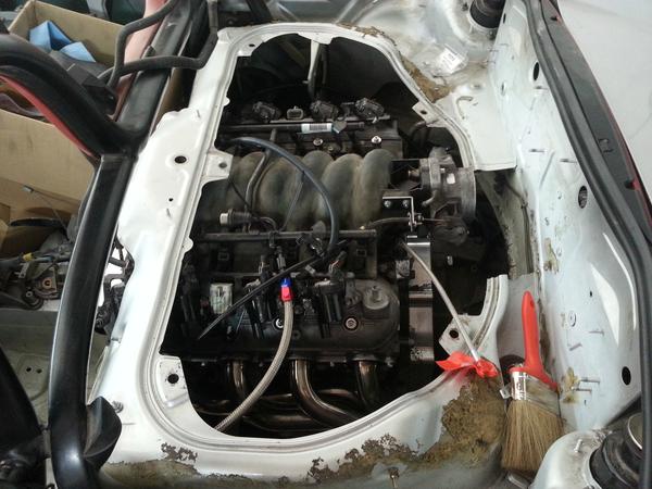
BTW, if you decide to run truck ignition coils (which are better than LS1 ones), the fuel rail connection will not clear. You have to cut the tab that holds it to the rest of the fuel rail and bend it off to the side. I don�t have an up close picture, but it should be visible in the one below.
GM fuel filter/regulator on the left, and Porsche fuel filter on the right
BTW, if you decide to run truck ignition coils (which are better than LS1 ones), the fuel rail connection will not clear. You have to cut the tab that holds it to the rest of the fuel rail and bend it off to the side. I don�t have an up close picture, but it should be visible in the one below.
08-22-2015, 03:35 AM
#75
I don’t have a hoist, so it was pretty difficult to snap good picture of the fuel system. Here is a basic diagram of how I did it. I decided not to run heater lines, since it will probably be hot enough in the car from the engine compartment. I do not plan to winter drive it.
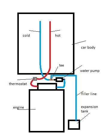
This is a pretty simplified diagram. You will also need a tee on the vent line, to hook up the engine vapour lines. It was impossible to find a 0.5″x0.5″x0.25″ tee, so I just put one together from plumbing parts. BTW, if you are looking for hose fittings or connections, head over to JTR (Jaguars that run) website.
The line sizes are:
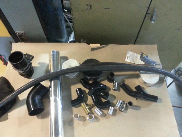
I suggest you get a reducing silicone sleeve on the main Porsche coolant lines (1.5″ to 1.25″), and then run the rest of the system in 1.25″. Make sure to stock up on unions and hose clamps. I think I used something like 30 clamps. Some 90 degree silicone or aluminum elbows will definitely come in handy.
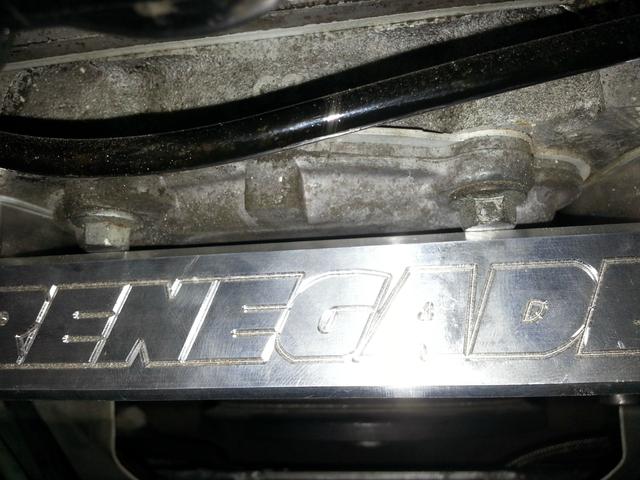
So Renegade made this beautiful aluminum intake, yet they couldn’t make enough clearance for the timing cover bolts… The heads are already filed down in the picture below.
This is a pretty simplified diagram. You will also need a tee on the vent line, to hook up the engine vapour lines. It was impossible to find a 0.5″x0.5″x0.25″ tee, so I just put one together from plumbing parts. BTW, if you are looking for hose fittings or connections, head over to JTR (Jaguars that run) website.
The line sizes are:
- Two big coolant lines running to radiators are about 1.5″
- The filler line is 0.75″
- The vent line is 0.5″
- Renegade fittings are 1.25″
- Thermostat housing is 1.25″
I suggest you get a reducing silicone sleeve on the main Porsche coolant lines (1.5″ to 1.25″), and then run the rest of the system in 1.25″. Make sure to stock up on unions and hose clamps. I think I used something like 30 clamps. Some 90 degree silicone or aluminum elbows will definitely come in handy.
So Renegade made this beautiful aluminum intake, yet they couldn’t make enough clearance for the timing cover bolts… The heads are already filed down in the picture below.