When you click on links to various merchants on this site and make a purchase, this can result in this site earning a commission. Affiliate programs and affiliations include, but are not limited to, the eBay Partner Network.
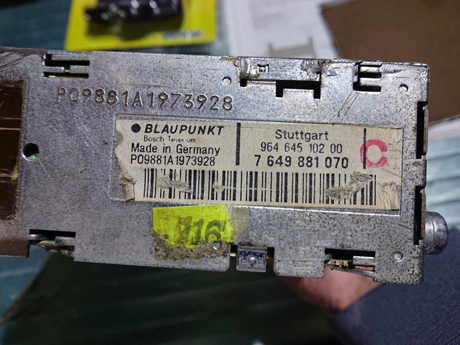
Let's start with one of the projects for my '87 Carrera 3.2. I purchased the car with a Blaupunkt Stuttgart installed, which is a unit coming from a 964, not the original Reno usually coming here with the late G-models. But I am happy with this unit as it looks mostly original and is more advanced technologically.
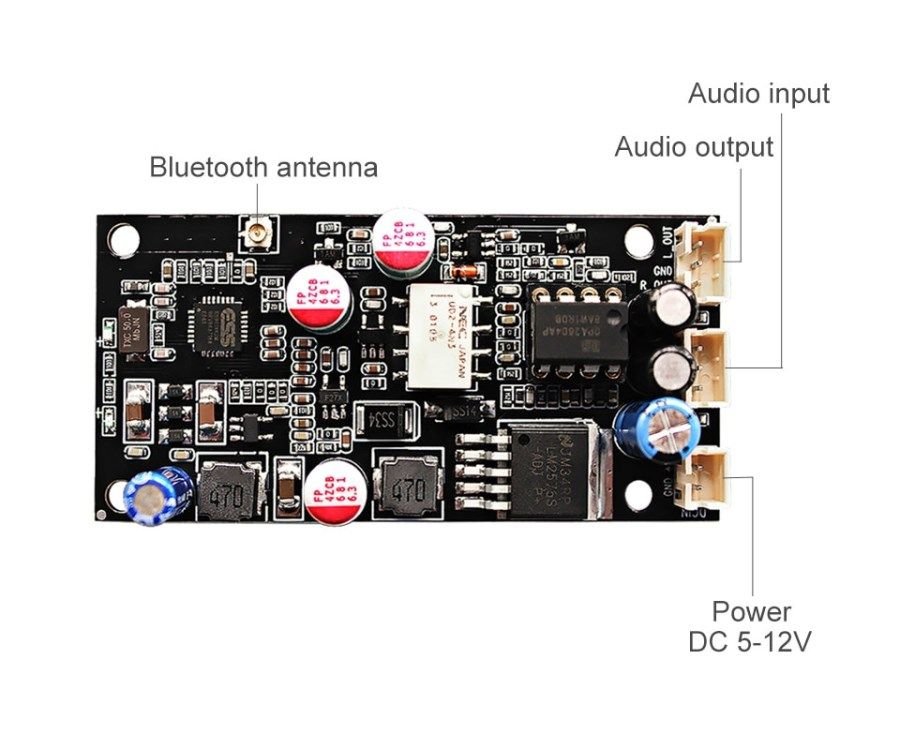
My idea is removing the cassette unit and installing on its behalf a board capable of injecting signal coming from bluetooth or an analog aux-in.
It is maybe the more expensive option for this conversion (around 35USD), as it has improved characteristics over other options:
- Bluetooth 5.0, which has improved bandwidth for audio transmission and lower energy consumption
- APTX-HD technology, which is capable of reaching CD quality
- 12V DC in, against others having 5V requiring an additional power converter.
- Aux-in, with automated switching to Bluetooth in when it gets connected
- Op-Amp for the output. I am not sure whether I will need them. If the radio accepts the signal without amplification it is just a matter of removing the IC and putting a jumper on the socket.
In the middle, there are many options and configured boards to choose
Here we have the Stuttgart from bottom side, nothing really interesting.
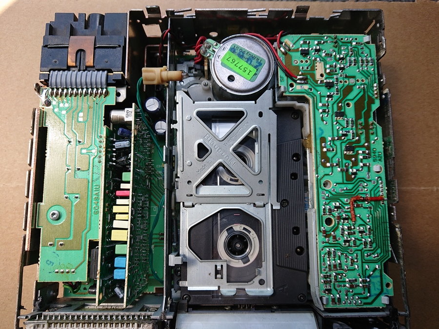
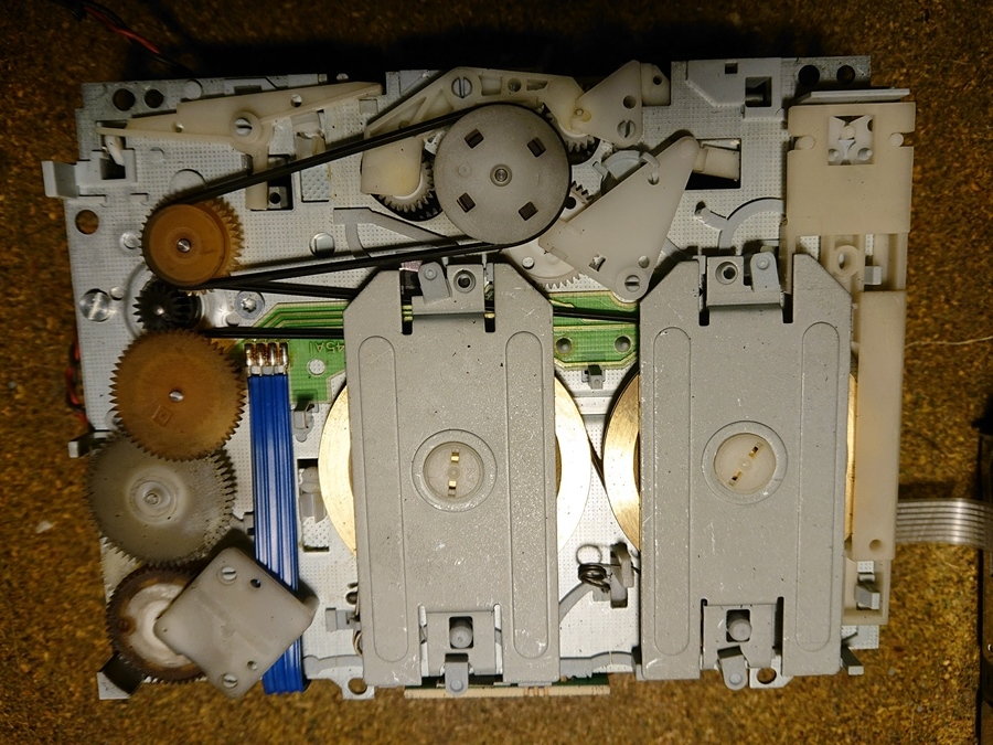
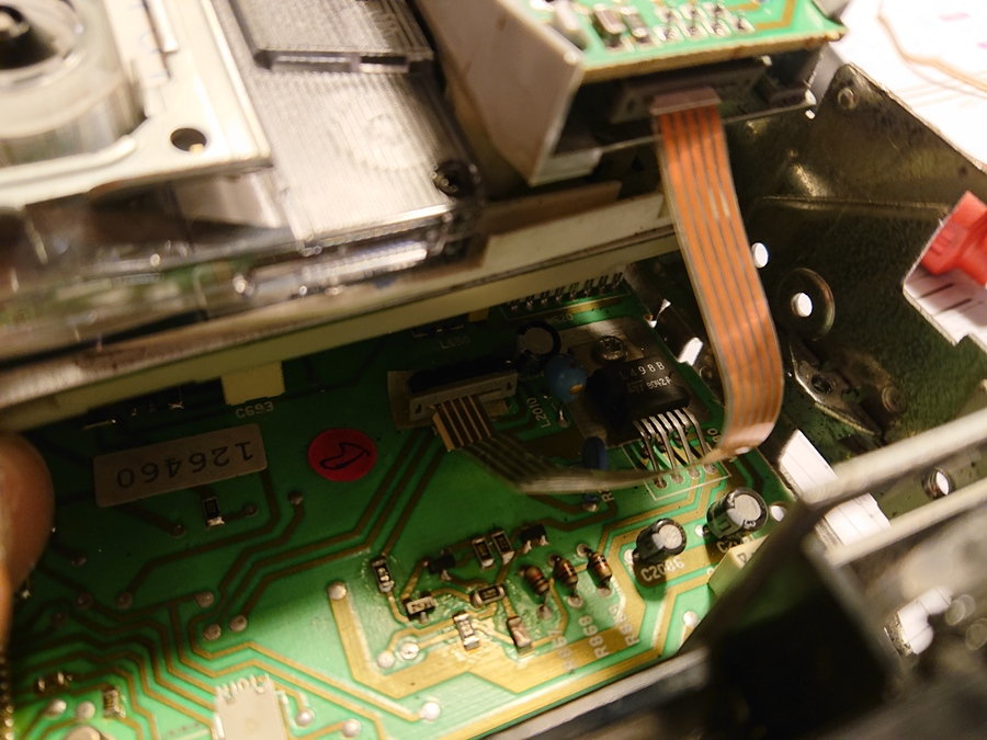
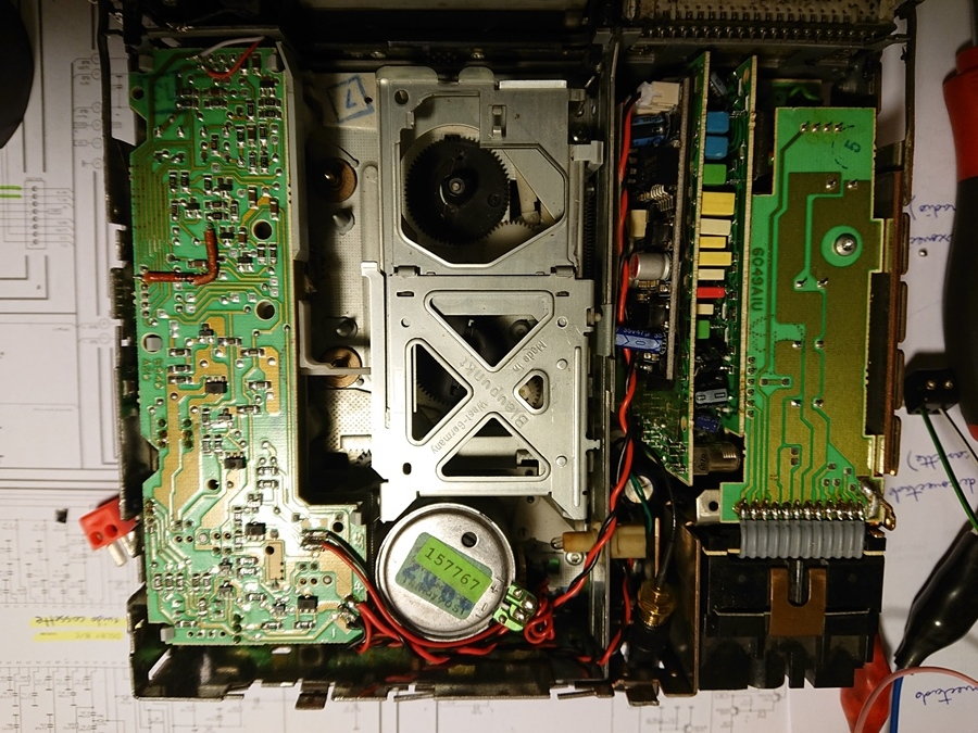
Cassette module is easily removed. This radio is quite complex for its time, it has plenty of daughter boards for the different systems,
I had taken apart other cassettes in the past, but this one is a marble of gear and pulleys, nice work by Blaupunkt
Easily identified are some Philips IC for the radio reception and the square processing unit. That guy seems to control all the systems around.
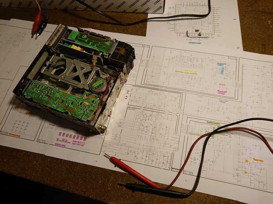
In order to start identifying the elements I got the documentation for the Bremen/Atlanta SQR49, which look quite similar but have realised are not the same. The connectors on the boards are numbered different and location of elements is also different. Does any have the diagram for the Stuttgart?
The basic idea of the conversion are two steps:
- Inject the audio output from the new board onto the points where the cassette module injects it to the radio originally.
- Remove the cassette module, generating the signal to cheat the radio and think it is still there. This way we can make use of the SRC button to change from radio to our new board.
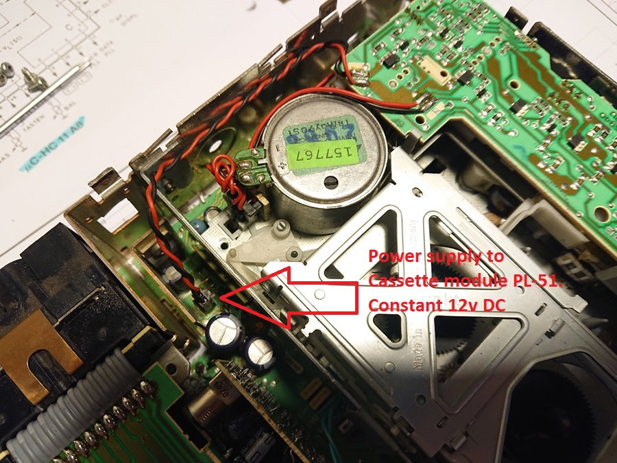
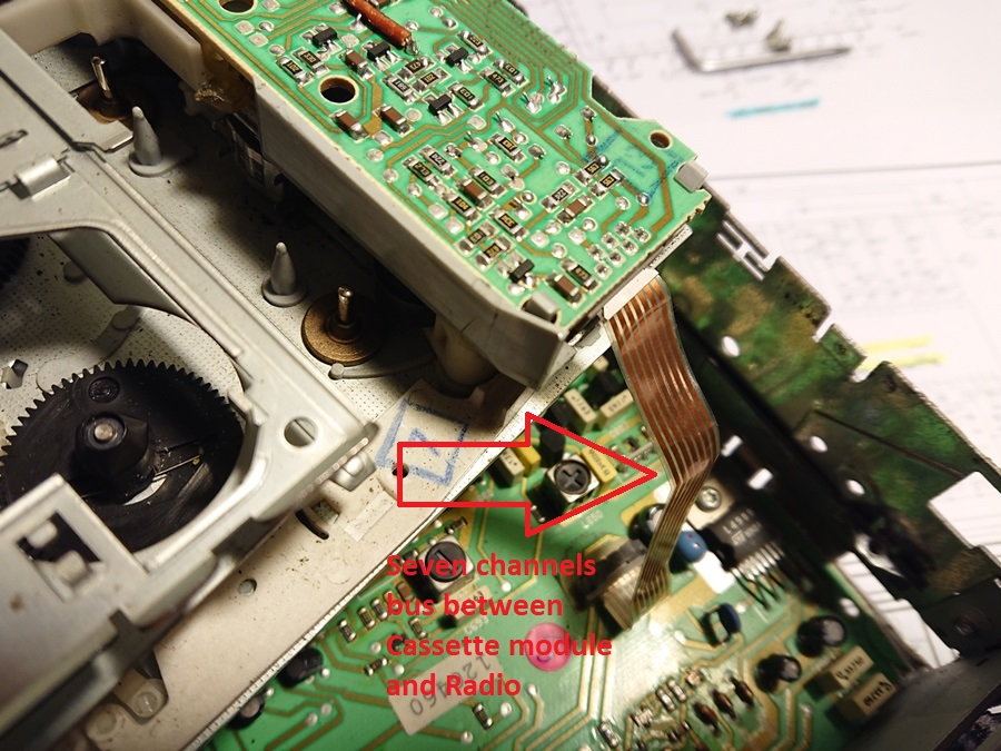
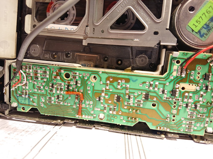
The cassette module only has 2 connections to the radio mainboard. One is a 12V DC, which is always powered when the radio is turned on. Nice place to get power for our board.
The other connection is a 7 channels bus, which I assume is for the L and R signal, plus other signals (cassette inside, change playing side, fast forward...) which I do not recognise. Only using a multimeter I have been measuring voltages on the 7 connections refer to the "-" from the power, with both the tape out and in respectively.
Pin 1 4.78V 4.78V
Pin 2 4.56V 4.56V
Pin 3 4.77V 4.77V
Pin 4 8.39V 8.39V
Pin 5 1.4mV 7.5mV
Pin 6 1.1mV 9.8mV
Pin 7 1.1mV 9.8mV
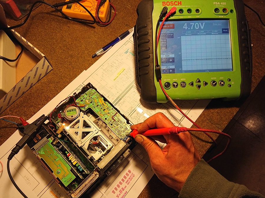
As the last 3 are on the range of milivolts and higher when the cassette is playing, I assum these are the L, R and ground for audio. The other 4 constant voltages I have no clue what they are for. I have manually actuated some of the swithches on the cassette module to see whether any value changes without success. My worry is that the processor communicates using a protocol instead of analog signals, so I will have to look for a oscilloscope to see whether they are wave signals.
On other easier radios I have opened there were switches indicating that a tape was inside, so cheating the radio was as easy as jumpering some wires to simulate a closed switch. Does anybody have information on how this could be managed?
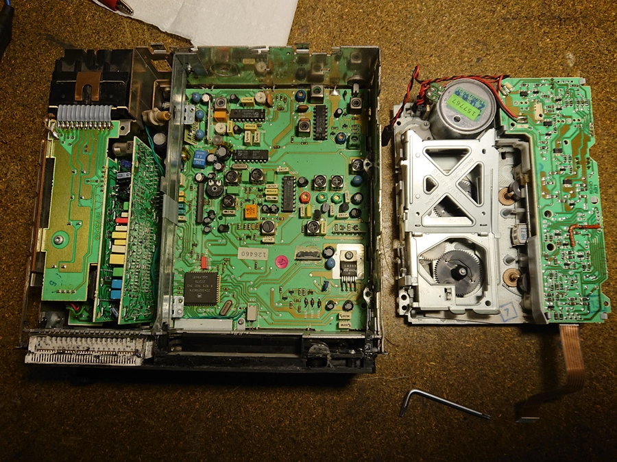
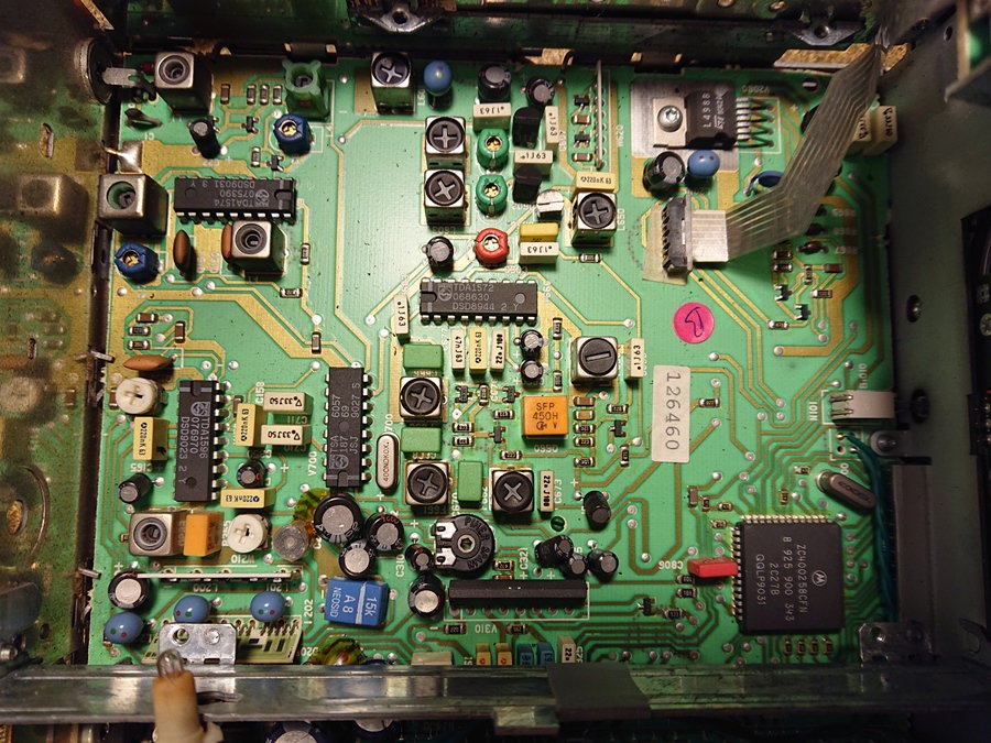
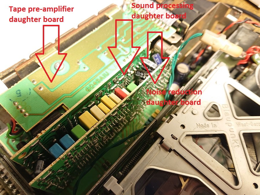
Just to identify some more elements, here are some additional daughter boards for sound procesing and amplification. The one in the middle has the IC which takes and processes the signal from Radio or tape.
I have been today trying to identify sinusoidal or coded signals on the 7 lines bus from cassette to radio without success. Four of the lines are just plain voltage values which do not change when tape is in or out. I even checked continuity between all pins in all status, and nothing changes.
Anyway, I have confirmed that the other 3 lines are L+ R+ and "-" given the shape of the wave read on the osciloscope.
Honestly, I do not really know how to go ahead in order the cheat the radio.
I ended up with the conclusion that this radio is relatively advanced electronicaly, and there is no easy way to make her think that the cassette is present. So I decided to change partially the path of the modification.
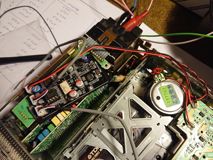
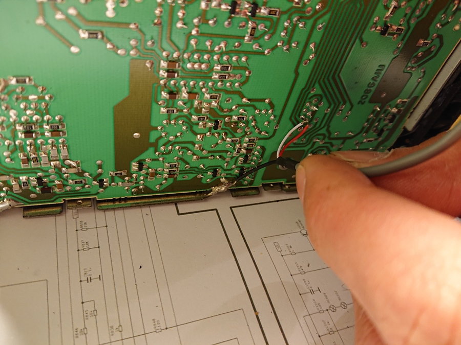
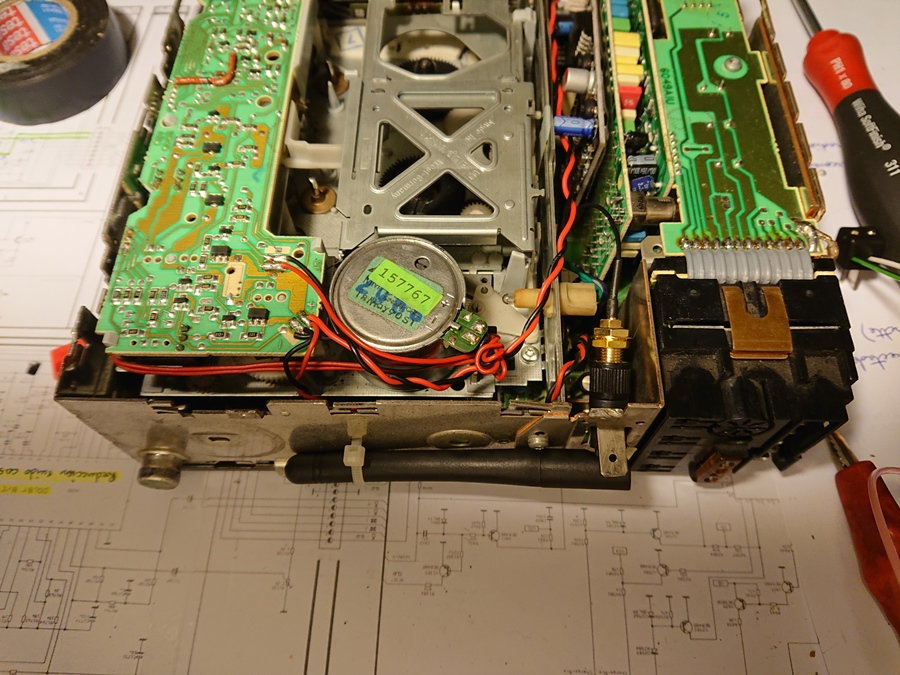
As the module I bought has an input line, which I wanted to use with a jack, I have used it to manage the audio signal from the cassette module. First thing is to get the 12v, which are easily available on the power for the cassette module.
Next step is to partially cut the data bus connecting the cassette module to the main board of the stereo. It is a 7 channels bus, where 5 lines are for various data and signals which are essential for the cassette to be recongnised so the SRC button is working. The last 2 are the L and R audio lines, so I cut them.
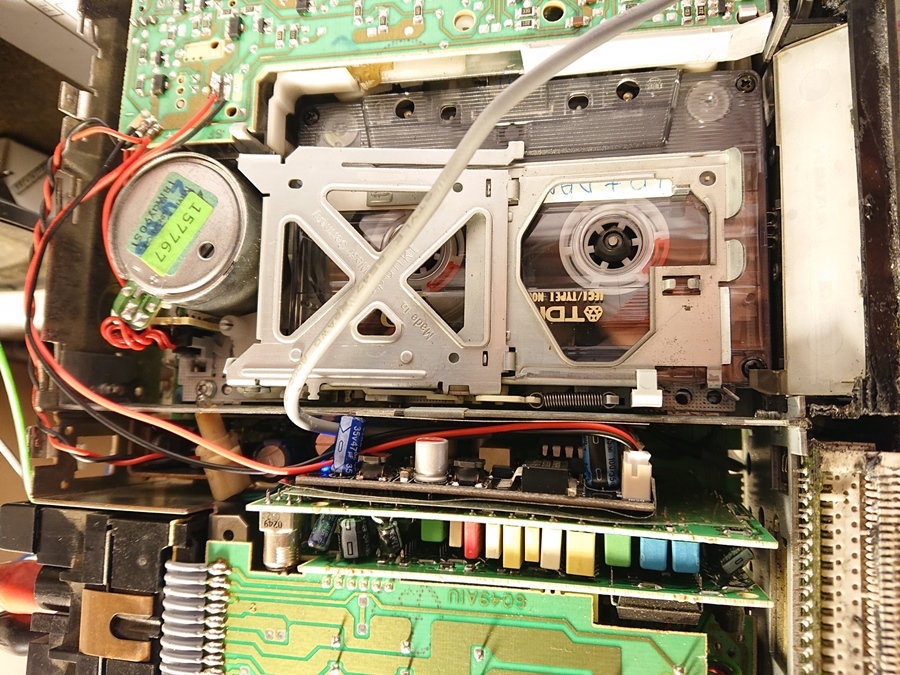
Next is to connect the output lines of the cassette daughter board to the Bluetooth board Input
Next is to connect the Output of the Bluetooth board to the stereo motherboard where the cassette signal were connected previously. This way we will manage the cassette audio with our new module.
Luckily ther eis space for the small board in vertical between other two daughter boards. Please note the plastic layers introduced to isolate them.
General view with all cables tied up and routed adeqautely throught the stereo.
Within a couple of meters, the bluetooth reception is correct, but further than that it starts gererating noise and interference. This is due to the faraday effect of the steel case of the stereo. To minimise this partially, I decided to install the external antenna at the back, which has mitigated the issue.
So now we have 3 different audio sources:
- If there is no cassette inside. We can only make use of the radio.
- If we introduce a cassette, we have access to the SRC button which will allow us conmuting.
- Once on tape mode, the default sound going out is the one of the cassette. If we start sending music through Bluetooth, the board automaticcaly conmutes to BT. If we stop sending bluetooth signal, it conmutes again to the cassette audio.
The only "issue" is that we need the tape to be playing to be able to make use of the Bluetooth. The stereo in fact thinks he is getting out the singal of the cassette, but we are modifying it with our new board.

 04-25-2019, 08:57 AM