When you click on links to various merchants on this site and make a purchase, this can result in this site earning a commission. Affiliate programs and affiliations include, but are not limited to, the eBay Partner Network.
I'm starting a project to retrofit the OEM tire pressure monitor system into my 2006 C2S as it was an option not included in my car. I have all the pieces (control unit, antennas, wheel transmitters, etc.) and will build the wire harness as my car does not have the spare connectors built in.
To help me, can someone post two pictures - front and rear wheel wells with the inner plastic wheel liner removed? I'm specifically looking for the TPM antenna mounting orientation and cable routing into the body of the vehicle. Is it vertically mounted? Horizonally? Where is the wire grommet to enter into the body?
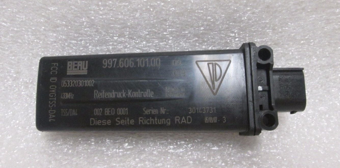
For reference a TPM antenna looks like this:
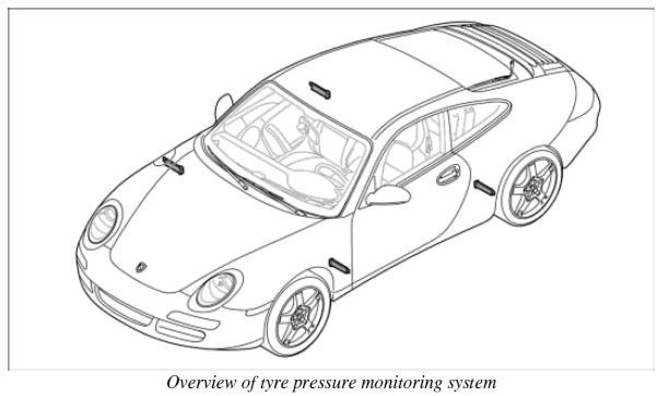
And the antennas should be mounted in these four locations:
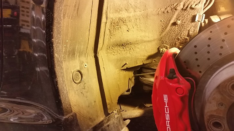
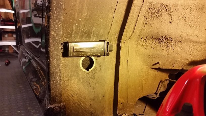
Rear left wheel well after removing liner, notice no TPM antenna present
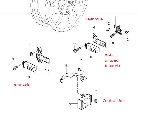
PET calls out two brackets #14 and #9, but it looks like #14 is not needed in my application (997.1 C2S Coupe). Only #9 is used. Is the extra bracket used on cabs instead perhaps?
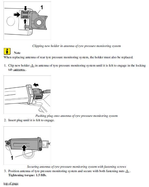
Workshop manual showing how to attach the rear bracket #9 from the PET diagram to the TPM antenna. Small end first then rotate (took me awhile to figure that out):
Temporarily mounting the rear left antenna. Not sure if I want to route the wire through this hole or not:
Still looking for OEM install pictures with cable routing. Can a kind soul post one please?
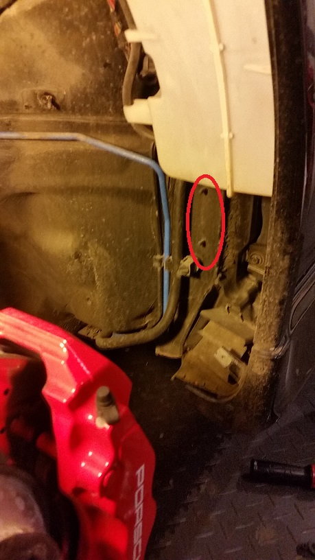
Front left with the inner plastic liner removed. The front looks to be straight forward. There are two mounting posts already present to accept the antenna and mounting bracket.
Before:
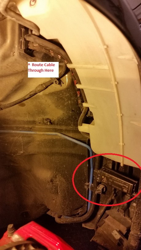
After, temporarily mounted the antenna. I'm likely going to route the cable along the other wires and into the frunk where noted.
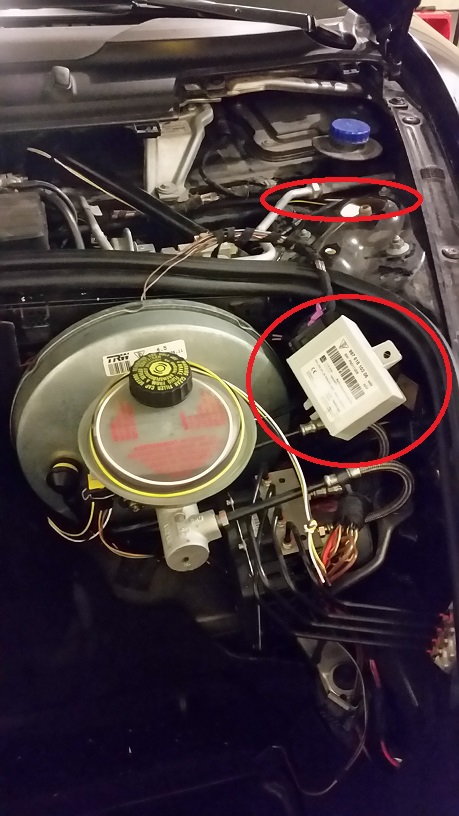
So more digging in the workshop manual. The front antenna connectors and the TPM control unit connector are part of the main wire harness in the front under the hood. Since my 2006 did not have the TPM option, those connectors are missing. Here's the routing from the workshop manual, marked up in red for my retrofit routing. #20 is the front left antenna, #19 front right antenna, and #15 the control unit.
Front left routing in progress. Slow going but a fun winter project.
So as usual life gets in the way with many of my projects. I went down a suspension upgrade path before completing the TPMS retrofit, replacing the remaining rubber suspension bits with monoballs first. The Tarret front camber plates did not fit in standard mode, so ended up with GT3 front camber plates instead. This was a good solid two month diversion between removing and reinstalling the fronts three separate times, rears once, and resetting ride heights twice after sufficient settling time. All this on weekends with Jack Point stands and DIY string alignments. The plus side is it's done, the car corners like a go cart, and I'm pretty good at DIY aligning my car now.
While I had the rear interior torn apart to get at the strut tops I did continue the TPMS retrofit a bit. The rear antennas are installed. I ended up routing the wires through this hole as it easily enters the rear cabin by the front seat belt.
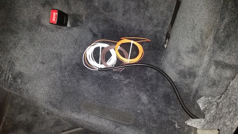
Here's what the rear left interior cables look like right now. The rear right is the same. The next step is to fish them under the carpet and through the center console area to the front firewall.
I'll have the center console out in the coming few weeks for a shifter upgrade and will do it then. Just waiting on the Numeric cup cables to begin that project. And I'm likely to do a radio head unit upgrade at the same time since the center console will be out. So this project will sit again for a while.
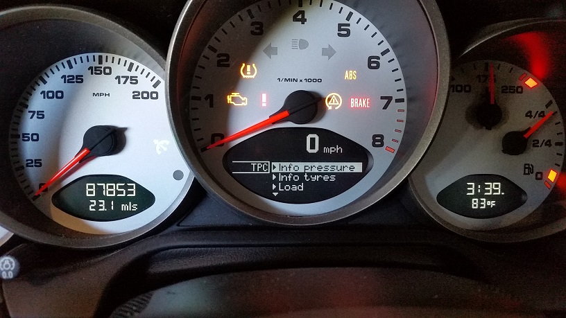
I had finished the install quite some time ago but was struggling with the coding. Durametric mostly got it working showing the differential pressure fills while stationary under the BC stalk Info->TPC settings. But I couldn't get the actual pressures to display with Durametric.
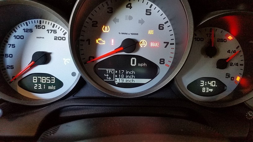
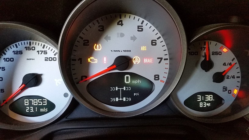
Lucky me I got a hold of a used PIWIS system - Panasonic CF-30 Toughbook with all the cables. Now the TPMS retrofit is complete. The cool thing is I can defined a "special" tire size with whatever pressures I want. Great for setting up track tires or for using lower than normal pressures on standard tires when cold.
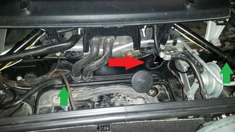
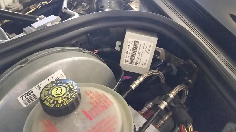
Rear antenna cables routed through the front firewall here at the red arrow:
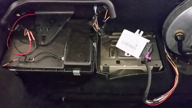
Final cables routed and connected to the control unit:
Mouser, Digikey, Newark, any of the electrical supply companies have them. Attached is my sales order from Mouser. The "ANT..." labels in the Customer Part # column are what you want, antenna side connector housing, crimp pins, and weather seals for the unused pins (or use silicone caulk). The "CU..." labels are for the control unit side.

 02-20-2016, 03:06 PM