When you click on links to various merchants on this site and make a purchase, this can result in this site earning a commission. Affiliate programs and affiliations include, but are not limited to, the eBay Partner Network.
PV997,
I agree with you and believe your desire to target a tiny sliver of late model Porsche owners is admirable. These are not Honda Civics and I'm betting exactly ZERO % of us live in a trailer park. Like it or not, most who read this have no intention nor means to actually replace the distance sensor themselves. Gaining knowledge is crucial but much different than doing the dirty work.
Personally, I have no problem paying a plumber thousands of dollars to replace fixtures and wrestle turds, work that I can obviously do myself, but life is short and I'm smart enough to stay in my wheel house where I can optimize my value. Between family, work, recreation, and church it certainly doesn't make intellectual sense for me to waste my precious time. When sizing up the late-model Porsche community as a whole, most owners feel the same way.
Thank you for all of your diligence and passion. I hope your next Heathkit experiment involves speed sensors because that's the other major failure we're seeing in PDKs.
I get it @notfastenough and appreciate the service both you and @toddlamb provide to the community. Your passions (family, work, recreation, and church) are exactly the same as mine and it would be great to sit down and chat one of these days.
Bottom line is that I'm cheap (to a fault) and don't like paying for things I can do myself. Plus, probably like you, I've been working on cars since I was a teenager and I don't think I've ever paid to have someone else work on my car. I enjoy the challenge, don't mind the time spent, and find it very rewarding. Probably since it's not my job, I also find it relaxing and therapeutic, particularly the sense of satisfaction from getting it done. I realize not everyone is like me though.
I'm appreciative that we now have far less costly options than Porsche, particularly for those who aren't comfortable with DIY for whatever reason. You and Todd have the experience on this and I've recommended you guys several times in the comments above. My main concern was an appearance that we had transferred the PDK priesthood (for lack of a better term) from Porsche to new, albeit less expensive, group of "authorized experts" (approved PDK repair shops). That wasn't the intent. We can have shops like Beck's and ATL Speedworks that have proven they know what they are doing while still recognizing that people can DIY this stuff with decent set of tools, mechanical aptitude, and some time.
If people want to hire someone to do this then that is great and more power to them, unlike me some people actually have a life and don't want to spend their weekends lying under a car. However, I don't want people to think they have no choice but to ship their car across the country to an "expert" shop. Like I said, the intent was not to create a new priesthood.
Anyways, I'm glad you guys (and Todd) are doing what you guys are doing along with getting the word out. It's all good.
Regarding the Heathkit distance sensor, things are progressing nicely (and we are looking at a speed sensor too). I've got the sensor components and programmer up and running and it's simpler than I thought. No bit-banging required as the programmer has a very nice GUI. One really nice thing is we can use this interface to program the sensor even after it's installed in the PDK if we need to make programming touch-up in the PDK environment. Once we are set, just hit that red "lock sensor" button and it can never be changed afterwards.
I also just received word that the first printed wiring boards (PWBs) have shipped and I should have them in a few days. Unfortunately after they started fab I realized I made a mistake on the dimensions so I'll need to do an update. These were for testing purposes and not the final product so it's no problem though.
Pretty amazing how simple this unit is using programmable Hall Effect sensors. Looking forward to having some test results posted soon.
@jjrichar thanks for your quick response, exactly the kind of info I'm looking for! thanks!
very interesting observation about the metal debris... my problem does seem to be intermittent, many instances of distance sensor problem I read here seems to be permanent so I was indeed very curious about if something is different with the intermittent ones...
I just want to give an update on my PDK journey - finally, the PIWIS 2 arrived and I did a clutch "recalib without parts replacement" and viola! The car is reversing properly again!
So the pattern is identical to the 1st time I ran into this problem - car threw error codes P0700 (Transmission control system (MIL Request)) and P1734 (displacement sensor), "transmission emergency run" message plus CEL on the dash, and couldn't reverse. Those codes can be cleared but a P1764 (Engagement block, synchronization or gear skip (No fault symptom available) would remain and still cannot reverse, but a recalibration with PIWIS 2 will put it back in working order.
My theory is my distance sensor is on the verge of failing and is giving intermittent erroneous readings, whenever it does somehow that throws a wrench to the clutch calibration. I found it somewhat interesting because I have read a few occurrences of intermittent distance sensors failure before they permanently fail, but in those cases, cars would be drivable simply by restarting the car after the intermittent failures, I haven't seen other people mentioning the car would need a PDK recalib after the intermittent failures. I thought my case is a little interesting in this regard and worth sharing here, in case other ppl run into similar pattern, might found temporary relief by doing clutch recalibrations.
I'm inclined to get the sensor replaced anyway now, even though the car is drivable for now after recalibrations. My thinking is just to follow the most obvious clue - if P1734 came up twice it is likely the root cause of the problem. Better do this now while the car is somewhat drivable than having to deal with transporting the car/getting stuck in a random parking lot when the sensor permanently gives out...
Last edited by byroncheung; 12-12-2022 at 11:27 AM.
Backstory: car has 79k miles, tracked 10 times a year, PDK clutch/gear oil changed with Driven fluids before and after track season. Car has been flawless, finished up a track weekend at Chuckwalla and a week later after daily driving it to work, my wife goes to start the car in the morning and display shows "Trans fault poss. No R gear. Drive on pos"
I had forward gears 1,3,5,7 so I drove to local Porsche race shop. They found 4 trans codes in TCM, but because most of their race cars are MT, they didn't want to proceed. They cleared codes and then there were no forward gears. Towed car to another shop recommend to me by LN Engineering and their diagnosis is as follows:
Transmission is showing codes. Car had 1, 3, 5 and 7 gears and codes were cleared. Now the car won't go into gear.
- Transmission codes.
- 4 codes PDK
- No Reverse Drive at first
- Had 1, 3, 5, 7 gears and was cleared by Vision Motorsports and now has none.
- Has a computer tune for the engine.
- Changed fluids with Driven before and after track events.
- Front trunk does not pop
Notes:
Checked with autologic but could not pull factory codes
Connected battery charger
Checked with piwis found following codes:
P1764 (synchronization, engagement block or gear skip)
P1765 (gear disengagement lock)
Current P1774 (gear valve two, hydraulic fault)
Current P1731 (displ. Sensor shift rod gears 4/6, implausible signal)
Current P1735 (distance sensor f. Shift rod 4/6-short term fault)
Followed fault finder for code P1774
It asked if fluid for clutch was full
checked clutch fluid found low
Performed filling procedure filled 1.0 qt
Cleared codes and checked operation found still inop
Initially no codes set took about 3 min of running to set fault code
Checked codes found
P1764 synchronization, engagement block or gear skip
Next morning rechecked fluid found good.
Checked codes found
P1731
P1735
P1764
Current P1870
Cleared and rechecked
Unable to clear
Checked fault findings on current code P1870
Says to calibrate shift rods
Performed calibration as piwis instructs
Unable to perform calibration due to fault codes not able to clear
Performed handover and checked transmission for operation. Found no trans operation but Code
P1764
Attempted calibration again
Will not calibrate with fault code present. Could not clear faults
Checked flow charts
Inspected wiring harness for damage
Harness has no signs of chafing or damage
Attempted another handover to clear faults
Faults still present
Unable to perform calibration
Performed hard reset on control unit
Tried to clear codes
Cleared codes After hand over
Performed a vehicle log and was able to perform calibration
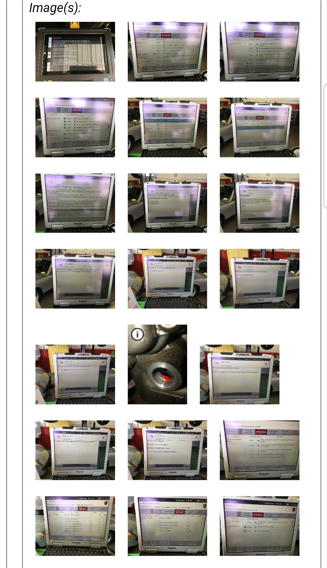
Unable to perform calibration- calibration failed during shift rod calibration (see picture)
Fault code
Current P1870
P1735
No matter how many times I get code P1870 to clear it will return.
Fault description of P1870 is �Data record for calibration of shift rods is not valid�
Remedy For fault is calibration
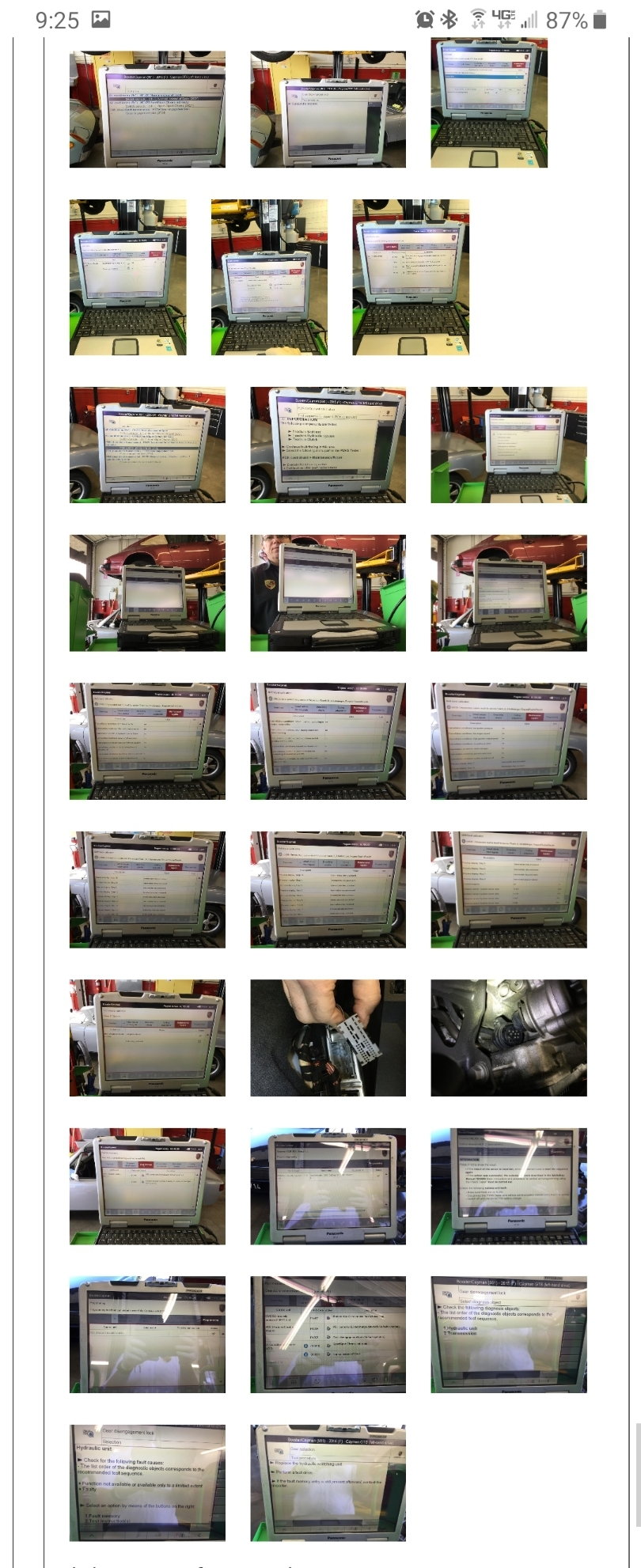
Unable to perform calibration found calibration failed �cancellation conditions: not all column can be reached with max force�
As per porsche document fault code coded a control unit from another vehicle to see if module was bad or transmission had fault.
Performed coding on a module and found
P174B- PDK control unit, interchange detected
P1765- Gear disengagement lock
As per fault code break down for P1765 asks to replace Hydraulic switching unit.
Due to erratic codes and complaint, suggest replacement of PDK trans and control unit.
After reading this thread, I feel compelled to call Porsche's bluff (according to Piwis diagnosis)by not replacing PDK and TCM, but instead replace hydraulic valve body and recalibrate the TCM. The shop purchased another Trans control module to try on my car as per Piwis instructions, and determined hydraulic failure, so if my TCM is fried they have a new one to try with a new hydraulic valve body
My logic is that due to the Piwis procedure screenshots above, it's clear that with either a malfunctioning hydraulic valve body and/or TCM, the calibration of the shift rods was unable to be performed..... no $hit! So the shops, and Porsche's solution is to replace everything . Bravo!
What kills me is that the trans pan wasn't even dropped to visually inspect for anything like metal shavings so how can it be concluded that there is any mechanical failure?
See the Porsche circular logic here? The calibration cant be performed because of malfunctioning hydraulic valve body so let's just replace the whole PDK because we're too lazy or scared to touch the insides of the transmission. Ironically, I had a B8 S4 with a similar ZF dual clutch that had a mechatronics failure, which was a widely known issue, simple fix was to replace valve body, clear codes, calibrate, then drive away happy. Will this PDK play ball?
If a new hydraulic valve body is installed and calibrated it should solve the problem. Or am I wrong?
Hi @Chris McSparron wonder if you ever find out what's exactly wrong with your PDK?
What are the chances that the distance sensor failures are not failures but some of the ferrous debris coating the magnets and interfering with the pick ups on the sensor? Giving it erroneous/implausible readings and causing the P17XX faults. Has anyone tested a "failed" sensor and determined it's actually failed or tried cleaning the magnets and retested the outputs?
What are the chances that the distance sensor failures are not failures but some of the ferrous debris coating the magnets and interfering with the pick ups on the sensor? Giving it erroneous/implausible readings and causing the P17XX faults. Has anyone tested a "failed" sensor and determined it's actually failed or tried cleaning the magnets and retested the outputs?
@jjrichar took a look at that as he found a surprising amount of magnetic sludge stuck to the magnets. He reported that cleaning them didn't seem to make much of a difference in the sensor output so it seems like it's not a major problem. He did note that the small clearance between the magnet and the sensor tends to push the sludge off to the side (during shift fork movement) so it didn't accumulate that much on the critical surfaces.
As part of our testing we'll add some iron filings and document how much it affects it.
I can use someone's help in trying to identify a suitable strain relief for the wires coming out of the sensor. See the whitish nylon piece (partially covered by potting) on the left hand side of the ZF sensor below. It looks like a Molex-style connector but it's actually an anchor for the wires so they don't stress the PCB connection if tugged. Note also how it has "ears" to hold it in place in the housing. If anyone knows where to find something like this (or something comparable) please let me know.
Things are moving along nicely as @jjrichar found someone to to the 3D CAD model of the housing and that's in work now. He thinks it might be possible to make it out of reinforced nylon rather than aluminum (similar to the speed sensor housing) but I'm somewhat skeptical mainly out of ignorance. If we have a materials property expert please take a look at what he wrote up over at Planet 9 and let us know what you think.
I've been able to repair and calibrate a few PDK transmissions. The one I have now is a 2014 Cayman non-S that had a faulty distance sensor. I installed the new one and I cannot get the calibration to finish. It errors(?) out at 50% of the way through the shift rod calibration process and stores fault code P1870 in the fault memory. Porsche's diagnostic sheet says to 'Calibrate Without Part Replacement' when P1870 is stored. I tried that and it errors out of Shift Rod Calibration again...at 50%. I've tried the calibration several times and get consistent results. Any advice? Thanks!
Thank to the OP and all who have contributed since. This is a wealth of information that isn’t found anywhere else I’ve seen. As a part time independent Porsche mechanic, this is just what I was looking for as more of my customers purchase PDK cars that need service and might throw a dreaded error at some point. When I can add some relevant additional information this is where I’ll post it.
I've been able to repair and calibrate a few PDK transmissions. The one I have now is a 2014 Cayman non-S that had a faulty distance sensor. I installed the new one and I cannot get the calibration to finish. It errors(?) out at 50% of the way through the shift rod calibration process and stores fault code P1870 in the fault memory. Porsche's diagnostic sheet says to 'Calibrate Without Part Replacement' when P1870 is stored. I tried that and it errors out of Shift Rod Calibration again...at 50%. I've tried the calibration several times and get consistent results. Any advice? Thanks!
Hi @hotrod512 - Do you have more info on the fault? P1870 has a few subcategories but I suspect it's "data record for shift rod compensation is invalid" but it could be something else. These types of errors (including the hydraulic teach-in error) have been discussed numerous times in the comments but unfortunately we never have come up with a definitive answer. I've long suspected it's due to the TCU's existing adaptation tables (developed using the old sensor) being inconsistent with the new sensor's characteristics but that's just a theory. Seems like the best approach is to wipe the TCU clean and start from scratch. PIWIS documentation is terrible though, so I don't have a clear answer on how to ensure this happens short of buying a new TCU. (BTW, I'm not suggesting you do that as I never recommend people throw expensive parts at a problem but to try and determine the root cause via diagnosis.)
Have you tried reading the sensor outputs using the PIWIS so see if the readings make sense and ensure there isn't a problem with the new sensor? Also, using a good multimeter with frequency and pulse width setting you can check the four distance sensor outputs. Freq should be between 800-1200 Hz and the duty cycle should be between ~20-80%. If the car was left in first gear sensors 1,2, and 4 should read around 50% DF and sensor 3 should be at an extreme. See jjrichar's video up in comment #1043 for more info on multimeter measurements.
Good luck and once you learn more or resolve this please come back and post the details. It's amazing how many people come here looking for free help, we spend our time with suggestions, then they *never* follow back up as to how things were resolved. Parents never taught them manners I guess. Thanks to the good folks that do follow up as we all learn from it.
Thank to the OP and all who have contributed since. This is a wealth of information that isn�t found anywhere else I�ve seen. As a part time independent Porsche mechanic, this is just what I was looking for as more of my customers purchase PDK cars that need service and might throw a dreaded error at some point. When I can add some relevant additional information this is where I�ll post it.
Thanks @cbracerx , looking forward to hearing more from you as we all unravel the PDK mysteries together.
Update on the low-cost distance sensor as I got the PWB assembled and installed in a dummy aluminum cavity for testing. The Hall Effect sensors are extremely easy to program and amazing versatile (and they only cost $3 each). Initial measurements look encouraging though I definitely need to make some modifications on Rev 2 of the PWB to move the sensor location to improve the sensitivity. No problems though as it's easily able to consistently measure 20 mm of magnet travel with good isolation between channels.
Here's a picture below showing the breadboard (not a prototype but a functional breadboard, the cheesy mock-up is for testing only). The housing is mocked up using 1/16" 6061 aluminum sheet metal held together with aluminum tape.
The capacitors will be replaced by high temperature SMT chip caps on the final design and the harness is a temporary attachment while we find a good connector candidate. You can see one HE sensor on the top of the PWB on the left (for the shift rod magnet that goes behind the distance sensor) while the other three are on the bottom side of the PWB. The PWB attachment is temporarily held together with nuts and bolts while we find a good solution. Interestingly there seems to be no effect on the HE sensors even using ferrous attachment hardware. Have not tried potting yet but we've found a good high temperature candidate.
Electrically this design is about as simple as they come and so far there are no surprises.
Thanks to jjrichar for his extremely detailed measurements on magnet location and travel distance to help get this dialed it. All thanks as he's getting the first housing fabricated for fit and alignment checks.
The capacitors will be replaced by high temperature SMT chip caps on the final design and the harness is a temporary attachment while we find a good connector candidate.
Suggest a multi-pin panel connector MIL- or auto-spec should suffice?
The panel option will give you the hard-point mounting tabs, or similar?
The Tyco, AMP, Amphenol catalogs would have such? Including some preterminated pin options?
But, I have to ask, why is a connector going to be needed, as otherwise the distance sensor and master plug would also need reterminating regardless?
If so, then soldering the new distance sensor to the existing in-car loom makes equal sense?
Or, are you working on the strategy of making this option plug-and-play replaceable after a main loom (inc speed sensor) are equipped with the comparable plug to mate with the new distance sensor socket?
Great steps forward regardless!
Glad to see donations of toast distance sensors going to good use!
Thanks Kuro, don't know if jjrichar told you but your sensor is here with me in California via Australia so it's had quite a trip.
By connector I mean a good way to launch the harness off the PWB. We could solder the wires directly but it's not very robust and would need a good quality strain relief. The other option is to extend the PWB to the left in the picture outside the electronics cavity and mount a 6-pin right angle connector. The harness would then plug into that using a hermetically sealed mating connector. It could be permanently attached or screwed on, whatever works better. I've been scouring connector catalogs from the companies you mention but have not found a good candidate yet. I need to get that locked down ASAP as I want to include the connector mount in the revised PWB layout.
I've got the PWB held in with nylon spacers and 4-40 hardware in the breadboard. For the real sensor we'll fab the housing with pedestals where the spacers are shown and tap them for screws holding the PWB down. The whole thing gets potted also so it will be belt and suspenders.
Thanks Kuro, don't know if jjrichar told you but your sensor is here with me in California via Australia so it's had quite a trip.
Germany, Japan, Aus, US... Indeed!
Originally Posted by PV997
By connector I mean a good way to launch the harness off the PWB. We could solder the wires directly but it's not very robust and would need a good quality strain relief. The other option is to extend the PWB to the left in the picture outside the electronics cavity and mount a 6-pin right angle connector. The harness would then plug into that using a hermetically sealed mating connector. It could be permanently attached or screwed on, whatever works better. I've been scouring connector catalogs from the companies you mention but have not found a good candidate yet. I need to get that locked down ASAP as I want to include the connector mount in the revised PWB layout.
I was going to suggest a pin-mounted 6-way, with a 90 degree socket, but seems you've got that on your agenda.
How about simple flying leads, and wrap posts molded into the body? You could then cap it, or the potting might provide enough strength?
It is after all, only needed for handling and installation as once installed load on the loom is static and contained by the securing clips?
Yup, looking at something very similar. You are right in that there's no strain on the wires in the PDK, the strain relief is to protect it from mishandling.
Thanks to Muddtt over at Planet 9 we now have a 3D CAD model of the housing.
It still needs a few tweaks but it's getting close. We are looking at both CNC machining using 6061 aluminum (more expensive but tried and true) and printed using glass-reinforced nylon (cheaper but some risk). The bolt holes are oversized to accommodate aluminum bushings if we go with a non-metallic housing, they'll shrink if we go with aluminum.
I've updated the PWB slightly based on electrical measurements on the breadboard. We'll probably do one more spin on this to finalize it. One thing I did realize is that the glass transition temp of FR-4 (common board material) is 140 deg C which is a bit too low for comfort so we'll probably switch to a higher temp material. If anyone has a background in this area please send me a PM.
UPDATE: Muddtt outdid himself as he printed a demo using ABS (what he had handy) for fit checks and testing!! If we do use a non-metallic housing it probably won't be this material (likely glass-infused nylon instead) but it does give us a good handle on printing dimensional tolerances and design clearances. Amazing stuff.
There's still some minor fixes needed to the housing design but we are getting close.


 12-10-2022, 10:41 AM