When you click on links to various merchants on this site and make a purchase, this can result in this site earning a commission. Affiliate programs and affiliations include, but are not limited to, the eBay Partner Network.
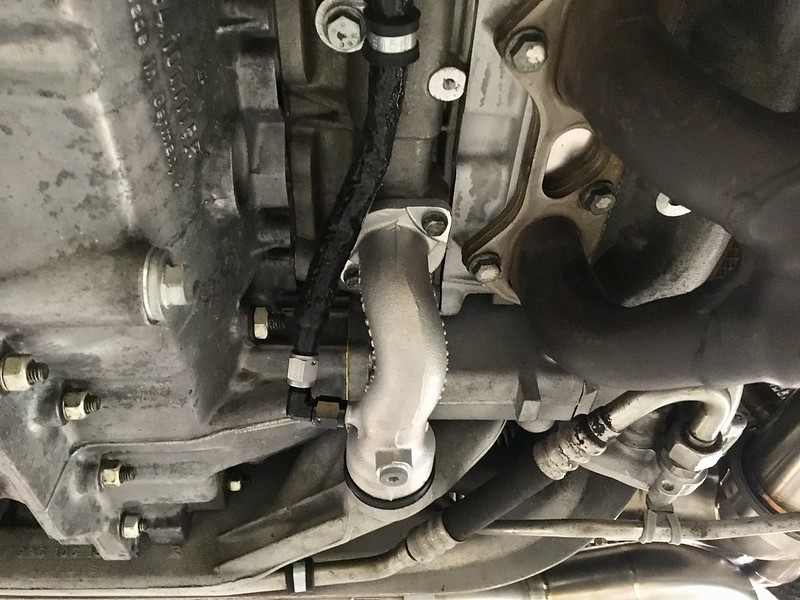
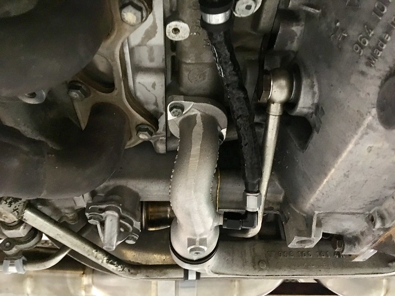
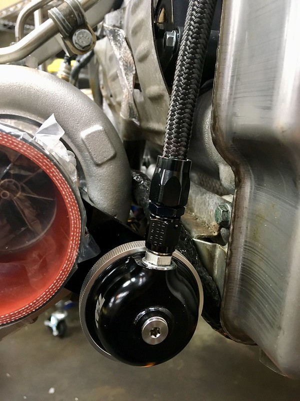
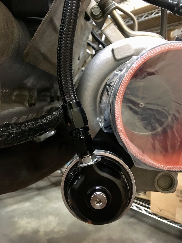
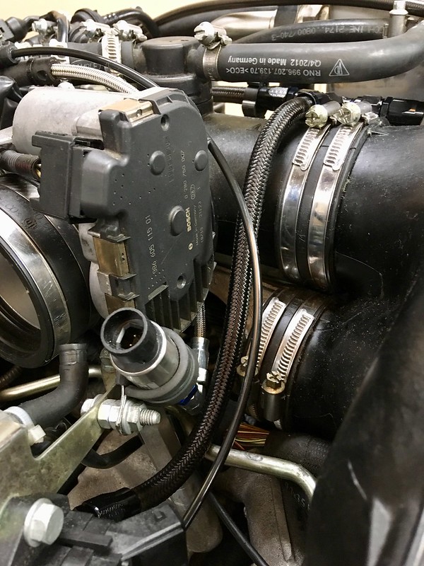
I had a few guys email me regarding the routing of water lines on Tial turbochargers. Here are a few pics of an effective way to do it. Having done this, one thing I did not like is the way that the lines are normally bolted to the bottom of the coolant drain plugs on the engine water pipe elbows. This makes it very simple but my worry was that this causes them to hang low on the engine thus exposing them to potential road/track debris. As I track my car exclusively and having run over tire chunks along with other items, I wanted a better way of doing this especial in light of the fact that my car runs a very low ride height and Murphy's Law states that if it can happen, it will. A solution to this was relatively easy as I simply removed the two coolant pipe sections at the bottom of the engine and had two aluminum -4AN bungs bungs welded on the side of the pipes which keep the lines nicely tucked away and thus protected. I then slipped fire/heat insulating hoses over the braided water lines and attached the lines with OEM pinch clips that were bolted to the unused threaded holes that are present on the bottom of the Mezger block. This makes for a very clean / OEM like install. While at it, I also installed -4AN lines and fittings from each turbocharger wastegate all the way to the N75 valve. This replaces the OEM rubber lines and plastic piping the factory uses. Using the -4AN braided lines makes for a bulletproof set up while making it a breeze to unbolt the lines from the WG itself. Cheers....
I can see why you didn't want those lines hanging off the bottom as they were. Nice customization.
How much HP/Torque do you think you will have?
A stock 3.6 block engine with the same turbochargers did 700whp/650wtq on 93 pump gas and 1.35 bar. With the larger 4.0 I'm thinking maybe 50 more than that but that's just a ballpark. For my use, that's about what I'd like to limit it to. I'll post up the sheet once we get the car on the dyno but that won't be for another month or so with ski season in full swing...
A stock 3.6 block engine with the same turbochargers did 700whp/650wtq on 93 pump gas and 1.35 bar. With the larger 4.0 I'm thinking maybe 50 more than that but that's just a ballpark. For my use, that's about what I'd like to limit it to. I'll post up the sheet once we get the car on the dyno but that won't be for another month or so with ski season in full swing...
nice mod powerhound, it the black black bulbous fitting a coolant pressure regulator? also what are the lines in your last pic going to? looks to be plastic. looks like a solid build alot to dial in.
nice mod powerhound, it the black black bulbous fitting a coolant pressure regulator? also what are the lines in your last pic going to? looks to be plastic. looks like a solid build alot to dial in.
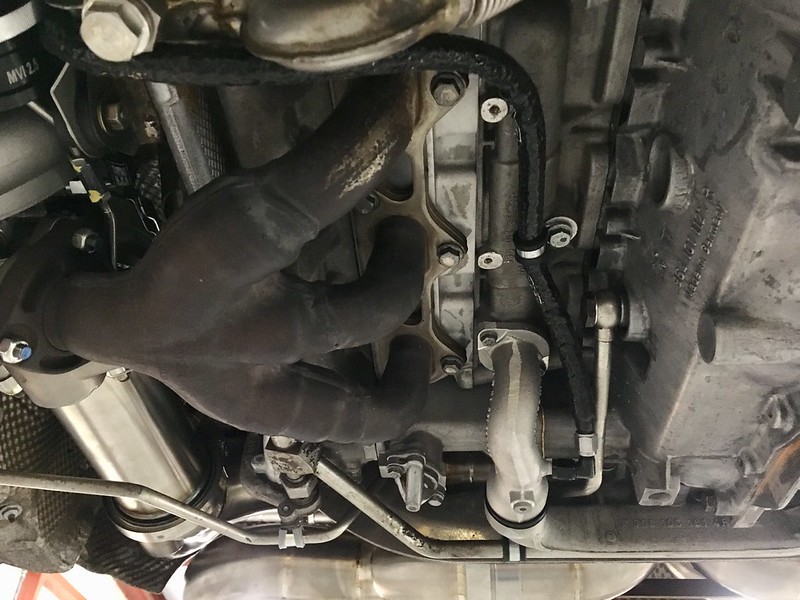
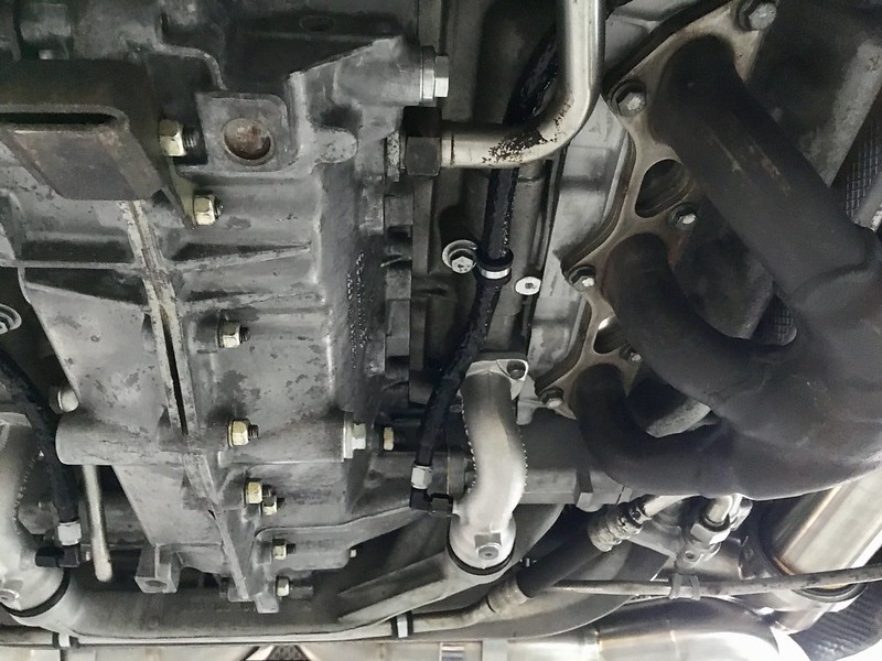
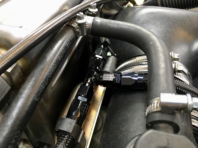
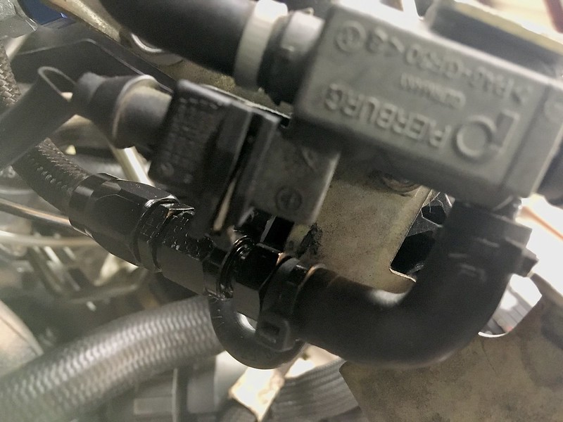
Hey Oak. If you are referring to the black "bulbous" fitting in pic 4 and 6 from the top, then those are the Turbocharger wastegates. The line in the last pic is the -4AN braided line connecting to the OEM rubber elbow that plugs into the N75 wastagete frequency valve. The rubber hose in the background visible there is an unrelated coolant hose further back.
Hey Oak. If you are referring to the black "bulbous" fitting in pic 4 and 6 from the top, then those are the Turbocharger waste gates. The line in the last pic is the -4AN braided line connecting to the OEM rubber elbow that plugs into the N75 wastage frequency valve. The rubber hose in the background visible there is an unrelated coolant hose further back.
thanks I gotcha, braided vac lines. for some reason I thought they were coolant lines. Im old. lol
thanks I gotcha, braided vac lines. for some reason I thought they were coolant lines. Im old. lol
The wastegate lines are actually pressure lines, NOT vacuum. Wastegate opening is actuated via boost pressure working against an internal wastegate spring which keep them closed.
yes! with your set up how much more pressure will be from stock?
Stock boost pressure is 0.8 to 0.9 if I recall. Most stock K16 tunes are 1.0 and K24 tunes are 1.1-1.2 on pump. My previous set up ran 1.25 bar on pump. Here we will probably run 20psi (1.35 bar) since the engine is a slightly lower compression at 9.0:1 vs the stock 9.4:1 compression. These turbochargers are frequently run at 1.8 to 2.0 bar in high HP applications so at 1.35 they will be barely loafing. Final decision will be made when we get into fine tuning everything but that is the target right now.
@powdrhound sorry also to chime in, but curious as to the volume of air within those pressure lines to the N75. Is the (functional) cross-section similar to stock, I would expect that it allows for much more volume, which could 'delay' accurate readings (overboost).
Perhaps that was something that Sam accounted for in the tuning?
Awesome reference material @powdrhound, thanks for always documenting/sharing your knowledge.
Curious how you ran the return lines for the Xonas? Did you use the Tial supplied splice fitting?
We used the Tial supplied lines and T fitting on my previous set up. On my current set we dripped and tapped the water pipes on top of the motor and are running the return lines direct to there. This simplifies things as there is nothing to disconnect when dropping the motor.
@powdrhound sorry also to chime in, but curious as to the volume of air within those pressure lines to the N75. Is the (functional) cross-section similar to stock, I would expect that it allows for much more volume, which could 'delay' accurate readings (overboost).
Perhaps that was something that Sam accounted for in the tuning?
The I.D. on the -4AM is 0.22" which is roughly comparable to the OEM rubber line. There have been zero issues with running the -4AN lines to the WGs. Nothing different done on tuning and I have several friends that run the same -4AN line WG set up on their car with the Xonas. We use a PTFE lined stainless -3AN vaccum/boost reference line that runs from the intake plenum all the way to the front of the car where the FPR is located in the trunk by the fuel tank as you can see in the picture below. That line is 0.125" ID.
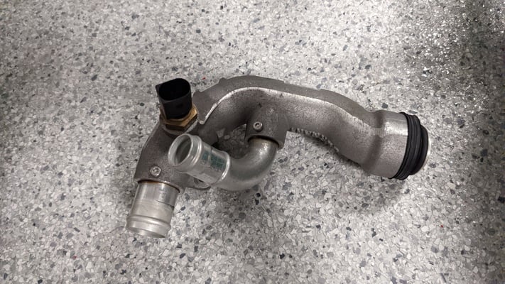
Hey @powdrhound do you happen to have any pics that show where you drilled/tapped the coolant housings for the return?
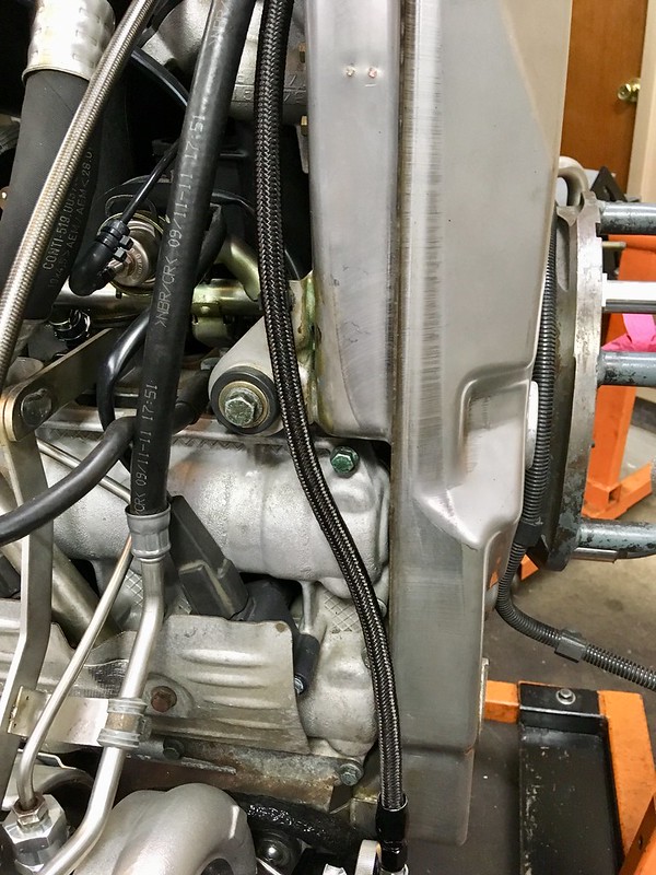
I'm planning to tap the housing on the driver's side of the engine in the picture attached.
Originally Posted by powdrhound
We used the Tial supplied lines and T fitting on my previous set up. On my current set we dripped and tapped the water pipes on top of the motor and are running the return lines direct to there. This simplifies things as there is nothing to disconnect when dropping the motor.

 01-15-2019, 06:11 PM